Note: Descriptions are shown in the official language in which they were submitted.
CA 02826619 2013-08-06
WO 2012/106750
PCT/AU2011/000639
- 1 -
DRILL RIG AND ASSOCIATED DRILL RIG TRAVERSE SYSTEM
Field of the Invention
The present invention relates to a drill rig and an associated drill rig
traverse
system which provides pull back and pull down force for the drill rig.
The present invention also relates to a drill rig traverse system for a drill
rig.
Background of the Invention
A typical drill rig comprises a tower which supports a drill head that in turn
rotates a drill string. The drill head linearly traverses up and down the
tower to
enable the drilling of a hole. The traversing of the drill head and drill
string is
effected by one or more hydraulic rams. When initially drilling the hole, the
hydraulic rams are operated to provide a pull down force to the drill string
in
order to enable it to penetrate into the ground. As hole depth increases, the
length and thus the weight of the drill string increases. Eventually the
weight of
the drill string will reach a point where it is necessary to apply pull back
to the
drill head to reduce the contact force or pressure of the drill bit on a toe
of the
hole. This extends drill bit life thereby reducing down time involved in
tripping
the string to change the bit. The maximum pull back force provided by the
hydraulic rams determines the maximum depth hole that can be drilled by a
particular drill rig.
Summary of the Invention
In broad terms, the present invention is a drill rig traverse system that
comprises in combination one or more rams to provide pull back and pull down
force, and a winch that can be selectively engaged with a drill head of a
drill rig
to provide additional pull back force. The pull back force provided by the
winch
may be multiplied by the use of a compound pulley system. Both the hydraulic
rams and the winch may be operated from a common hydraulic fluid source. It
is envisaged that the winch will be engaged with the rotation head at least
once
the depth of the hole has reached a point where pull back force is required to
be applied to the drill string. More particularly, the winch may be engaged
once
a maximum pull back force that can be provided by the hydraulic rams has
CA 02826619 2013-08-06
WO 2012/106750
PCT/AU2011/000639
- 2 -
been reached.
One aspect of the invention provides a drill rig traverse system for a drill
rig
having a drill tower and a rotation head linearly traversable on the drill
tower,
the drill rig traverse system comprising:
ram traverse system having at least one ram capable of providing both
pull down and pull back force to the rotation head and arranged to traverse
the
rotation head for substantially a full length of an associated drill tower;
and,
a winch pull back system selectively engagable with the rotation head to
provide additional pull back force to the rotation head, the winch pull back
system having a winch that in use is mounted on the tower.
In one embodiment the winch pull back system applies pull back force to the
rotation head through a pulley arrangement which is arranged to provide a
mechanical advantage of two or more.
The pulley arrangement may comprise a compound pulley having a moveable
axle on which a plurality of pulley wheels is rotatably supported.
The movable axle may be selectively engagable with the drill head.
The pulley arrangement may comprise a fixed axle which is fixed to the drill
tower and wherein a plurality of pulley wheels is rotatably supported on the
fixed axle.
In one embodiment the winch is mounted on the drill tower below a drill table
of
the drill rig.
The at least one ram may be attached to a top end of the drill tower.
The drill rig traverse system may comprise a releasable locking mechanism
capable of releasably locking the movable axle to the rotation head.
In one embodiment winch pull back system and the ram traverse system are
arranged to apply equal pull back force when the winch is engaged with the
rotation head. In this embodiment the drill rig traverse system comprises a
hydraulic fluid supply system and wherein the winch pull back system is
CA 02826619 2013-08-06
WO 2012/106750
PCT/AU2011/000639
- 3 -
hydraulically operated, the hydraulic fluid supply system being arranged to
provide hydraulic fluid to both the winch pull back system and the ram
traverse
system.
In another embodiment the winch pull back system and the ram traverse
system may be arranged to apply equal pull back force when the winch is
engaged with the rotation head up to a first force being the a lowest of the
maximum pull back capacity of the winch pull back system and the ram traverse
system. In this embodiment the drill rig traverse system comprises a hydraulic
fluid supply system and wherein the winch pull back system is hydraulically
operated, the hydraulic fluid supply system being arranged to provide equal
hydraulic fluid pressure to both the winch pull back system and the ram
traverse
system up to a first pressure being the pressure at which the first force is
reached.
The drill rig traverse system may comprise a hydraulic fluid supply system
which provides hydraulic fluid to both the winch pull back system and the ram
traverse system.
The hydraulic fluid supply system may provide equal hydraulic fluid pressure
to
both the winch pull back system and the ram traverse system up to a first
pressure being the pressure at which the first force is reached.
The hydraulic fluid supply system may be arranged to provide higher fluid
pressure than the first pressure to the winch pull back system or the ram
traverse system, which ever has the higher force rating, wherein the maximum
pull back provided by the drill rig is the sum of the maximum force rating of
the
winch and the maximum force rating of the ram traverse system.
In an alternate embodiment the winch pull back system is electrically
operated.
The ram traverse system may comprise one or more rams and a ram pulley
system arranged to cause the rotation head to traverse along the tower by a
distance twice an extension or retraction displacement of the one or more
rams.
In a second aspect the invention provides a method of drilling a hole
comprising:
CA 02826619 2013-08-06
WO 2012/106750
PCT/AU2011/000639
- 4 -
providing a drill rig having a drill tower, a rotation head linearly
traversable along the drill tower arranged and a ram traverse system having at
least one ram coupled to rotation head and the drill tower to provide pull
back
and pull down force, the ram traverse system arranged to traverse the rotation
head for substantially a full length of the tower;
operating the drill rig to drill a hole to a depth where pull back force is
required to be provided by the ram traverse system during drilling of the
hole;
and,
mounting a winch of a winch pull back system on the drill tower;
engaging the winch pull back system with the rotation head to provide
additional pull up force while simultaneously operating the ram traverse
system
to provide pull back force to the rotation head drill rig to drill the hole.
Operating the drill rig to drill a hole may comprise operating the drill rig
to drill
the hole to a first depth limited by a maximum pull back force provided by the
ram traverse system, and engaging the winch pull back system with the rotation
head and operating the drill rig to continue drilling the hole to a second
deeper
depth limited by a combined pull back force of the ram traverse system and the
winch pull back system.
The method may comprise operating the winch pull back system and the ram
traverse system from a common hydraulic fluid supply.
In one embodiment the method may comprise operating the winch pull back
system and the ram traverse system to apply equal pull back on the rotation
head up to a maximum pull back being twice the pull back of the maximum pull
back provided by either one of the winch pull back system and the ram traverse
system when the maximum pull back provided by the winch pull back system
and the ram traverse system are the same.
In an alternate embodiment the method may comprise operating the winch pull
back system and the ram traverse system to apply equal pull back on the
rotation head up to a maximum pull back being twice the pull back of the
lowest
maximum pull back provided by the winch pull back system and the ram
traverse system when the maximum pull back provided by the winch pull back
system and the ram traverse system are different. In this embodiment the
method may comprise upon reaching the pull back force of winch pull back
CA 02826619 2013-08-06
WO 2012/106750
PCT/AU2011/000639
- 5 -
system or ram traverse system having the lowest maximum pull back capacity,
providing additional hydraulic pressure to the winch pull back system or ram
traverse system having the highest maximum pull back capacity wherein the
maximum pull back provided is the sum of the maximum pull back of winch pull
back system and the ram traverse system.
A third aspect of the invention provides a method of increasing the drill
depth
capacity of a drill rig having a drill tower, a rotation head traversable
along the
drill tower and a ram traverse system having at least one ram capable of
providing both pull down and pull up force to the rotation head and traversing
the rotation head for substantially a full length of the tower, the method
comprising: mounting a winch of a winch pullback system on the tower and
selectively engaging the winch pull back system with the rotation head to
provide additional pull back.
The method may comprise strengthening the drill tower to bear a load up to at
least the sum of the load that can be supported by the ram traverse system and
the winch pull back system in combination.
A fourth aspect of the invention provides a drill rig comprising:
a drill tower and a rotation head traversable along the drill tower;
a ram traverse system having at least one ram capable of providing both pull
down and pull back force to the rotation head and arranged to traverse the
rotation head along substantially a full length of the tower;
a winch pull back system having a winch mounted on the drill tower, the
winch pull back system selectively engagable with the rotation head to provide
additional pull back force to the rotation head.
In one embodiment the tower is arranged to be selectively moveable between a
substantially horizontal position and a substantially vertical position while
the
winch pull back system is engaged without traversing the rotation head along
the tower.
Brief Description of the Drawings
An embodiment of the present invention will now be described in detail with
reference to the accompanying drawings in which:
CA 02826619 2013-08-06
WO 2012/106750
PCT/AU2011/000639
- 6 -
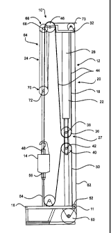
Figure 1 is a side view of a drill rig incorporating an embodiment of the
drill rig
traverse system in accordance with the present invention; and,
Figure 2 is a front view of the drill rig shown in Figure 1.
Detailed Description of Preferred Embodiment
Figures 1 and 2 illustrate a drill rig 10 comprising a drill tower 12,
rotation head
14 and drill table 16. Drill tower 12 is in the form of a rectangular box
frame 18
and is of fixed length. Drill table 16 is provided at a lower end of the frame
18
when the drill rig 10 is in a drilling position. Rotation head 14 provides
torque to
a drill string (not shown) used for drilling a hole. The drill string passes
through
a slips (not shown) provided on drill table 16 which is operated in a
conventional manner to enable the adding or breaking of a joint. Rotation head
14 is supported on and linearly traversable along drill tower 12.
Drill rig traverse system 20 provides pull back and pull down force to the
rotation head 14 enabling the rotation head 14 to traverse along drill tower
12
and controlling contact force between the drill bit and toe of a hole being
drilled.
Traverse system 20 comprises the combination of a hydraulic ram traverse
system 22 which provides both pull back and pull down force; and a winch pull
back system 24 which provides pull back only.
In this particular embodiment the hydraulic ram traverse system 22 comprises
three hydraulic rams 26a, 26b and 26c (hereinafter referred to in general as
"rams 26"); and hydraulic pulley system 27 which comprises: travelling sheave
34; pulleys 46 and 54; and pull back and pull down ropes/chains 44 and 50.
Each ram 26 comprises a corresponding cylinder 28 and piston 30. The
cylinders 28 are attached or mounted to a top frame portion 32 of tower frame
18. Pistons 30 of the rams 26 are coupled to the travelling sheave 34 which
comprises a set of pull back pulleys 36 mounted on a common axle 38; and a
set of pull down pulleys 40 mounted on a common axle 42. Pull back ropes or
chains 44 (hereinafter "ropes 44") are attached at one end to the top frame
portion 32; travel about and seat in respective pull back pulleys 36; travel
about
and seat in respective pull back top pulleys 46 mounted on the top frame
portion 32; and, are subsequently attached at end 48 to an upper portion of
CA 02826619 2013-08-06
WO 2012/106750
PCT/AU2011/000639
- 7 -
rotation head 14.
Pull down ropes or chains 50 (hereinafter "ropes 50") are: attached at one end
52 to a lower end of drill tower 12 near drill table 16; travel about and
engage
respective pull down pulleys 40; travel about and engage respective bottom
pull
down pulleys 54; and, finally attach at a distal end 56 to a lower end of
rotation
head 14.
When hydraulic fluid is provided to the rams 26 to extend their respective
pistons 30, the travelling sheave 34 moves linearly in a downward direction
providing pull back force to the rotation head 14 extending to traverse
rotation
head 14 in an upward direction along the drill tower 12. In contrast when
hydraulic fluid is provided to rams 26 in a manner to cause retraction of
pistons
30, the travelling sheave 34 moves in an upward direction and applies a pull
down force to rotation head 14 through the pull down ropes or chains 50. In
this way the hydraulic ram traverse system 22 is able to traverse the rotation
head 14 linearly up and down the drill tower 12.
The hydraulic ram traverse system 22 is able to cause the rotation head to
traverse substantially the full length of tower 12. This arises from a
combined
effect of the length of the rams 26 and hydraulic pulley system 27. The
hydraulic pulley system 27 traverses the rotation head 14 along the tower 12
by
twice the extension or retraction displacement of the ram 26. For example a
one metre extension of ram 26 provides a two meter displacement of the
rotation head along tower 12. This is due to the provision of the travelling
sheave 34 and the coupling of the rotation head at opposite ends to the pull
back and pull down ropes 44 and 50. Each ram 26 is arranged to have a length
of about one half the length of the tower 12, and associated piston 30 to have
a
maximum extension of about one half of the length of the tower. Thus operating
the rams 26 to fully extend the pistons from their full retracted position,
enables
the rotation head to traverse the full length of tower 12 between pulleys 46
and
54.
The pull back and pull down ropes 44 and 50 are rated to bear the maximum
pull down and pull back forces that can be applied by the hydraulic ram
traverse
system 22. When hydraulic ram traverse system 22 comprises a plurality of
rams as in the present embodiment, the rams may be operated to either act
CA 02826619 2013-08-06
WO 2012/106750
PCT/AU2011/000639
- 8 -
together in a conventional manner (i.e. all operated simultaneously under the
same hydraulic pressure) , or in a progressive manner as described in
Applicant's co-pending international application no. PCT/AU2010/000323 the
contents of which is incorporated herein by way of reference.
However by way of brief explanation the progressive system described in
PCT/AU2010/000323 comprises a plurality of rams which can apply pull back
and pull down force to a rotation head via a travelling sheave. The rams are
selectively operable to enable the pull back applied to the rotation head to
be
selectively varied and indeed progressively increased or decreased. In one
example the progressive system comprises first, second and third rams.
Initially
the first ram is selected ("switched in") to operate to drill to a first
depth. When
the maximum pull back available from the first ram is reached, this ram is
decoupled ("switched out"), and the second and third rams are selected to
operate to enable drilling to a second greater depth. When it is required to
drill
to a deeper third depth, all three rams are selected to apply pull back to the
rotation head. The rams are arranged to symmetrically apply force to the
travelling sheave as they are switched in or out.. So if say the first ram is
arranged along a line of symmetry of the travelling sheave then the second and
third rams are disposed equal distance one to each side of the first ram. To
progressively increase the pull back force that can be applied to the rotation
head initially only the first ram is switch in; then the first ram is switched
out and
only the second and third ram are switched in; and finally all three are
switched
in. In each instance the total force applied by the switched in ram(s) is
applied
symmetrically to the travelling sheave. The rams 26a ,26b and 26c of the
present embodiment may be operated in this manner if desired.
The winch pull back system 24 comprises a winch 60 which in this embodiment
is mounted to the drill tower 12 at a location near and below drill table 16.
Winch 60 is selectively engagable with the rotation head 14 to provide
additional pull back force via rope or chain (hereinafter referred to in
general as
"rope") 62. In this embodiment to provide mechanical advantage, the winch pull
back system 24 incorporates a compound pulley system 64 about which rope
62 travels. Compound pulley 64 comprises in this embodiment a set of five
pulleys 66a ¨ 66e (hereinafter referred to in general as "pulleys 66") each of
which is rotatably mounted on a fixed axle 68 coupled to the top frame portion
32 of drill tower 12. Compound pulley 64 further comprises a set of pulleys
70a
CA 02826619 2013-08-06
WO 2012/106750
PCT/AU2011/000639
-9-
- 70e (hereinafter referred to in general as "pulleys 70") each of which is
rotatably mounted to a common movable axle 72. Rope 62 is wound about
pulleys 66 and 70 to provide the required mechanical advantage. In the
present depicted embodiment rope 62 is wound about four fixed axle pulleys
66a-66d and four movable axle pulleys 70a-70d to provide a four times
mechanical advantage in pull back force. That is for example, if winch 60 and
rope 62 are rated to provide a force of 25 tonne, then by virtue of the
compound
pulley 64 and the winding of rope 62 about four of the pulleys 66 and 70, the
total maximum pull back force that can be provided by winch 60 is 100 tonnes.
Winch rope 62 extends from winch 62 via a first idler pulley 71 near table 16
and a second idler pulley 73 mounted on top frame portion 32 to the compound
pulley 64.
A hook assembly 74 is provided at an upper end of rotation head 14 to enable
the selective engagement of winch 60 with rotation head 14. Hook assembly
74 comprises two shackle pin hooks 76 which can engage the movable axle 72.
A locking mechanism (not shown) may be provided to releasably lock the axle
72 to the hook assembly 74.
The winch pull back system 24 is also able to traverse the rotation head
substantially the full length of drill tower 12. Thus both hydraulic ram
traverse
system 22 and winch pull back system 24 can be simultaneously connected to
the rotation head 14 and apply pull back force while traversing the rotation
head
14 for substantially the full length of the tower 12.
In one embodiment, both the ram traverse system 22 and the winch pull back
system 24 are operated by a common hydraulic fluid supply or motor. Further,
the systems are arranged so that each is provided with the same fluid
pressure.
For example respective hydraulic lines (i.e. hose) couple the common hydraulic
supply to the systems 22 and 24. However, if systems 22 and 24 have a
different maximum force/load rating or capacity, then fluid pressure is
limited or
diverted from the system having the lowest maximum force rating once the
pressure commensurate with that force rating is reached. This can be achieved
by use of a pressure relief or limiting valve in the hydraulic line between
the
common hydraulic supply and the system 22, 24 having the lowest maximum
force rating. Say for example that the ram traverse system 22 has a maximum
CA 02826619 2013-08-06
WO 2012/106750
PCT/AU2011/000639
- 10 -
force rating or pull back of 150 tonne and the winch pull back system 24 has a
maximum rating of 100 tonne (being 25 tonne times the 4 times mechanical
advantage provided by compound pulley 64). Initially drilling is conducted
using
the ram traverse system 22 only to provide pull down and pull back force.
When the depth of the hole (i.e. length of the drill string) reaches a stage
where
the maximum pull back of 150 tonne provided by the ram traverse system 22 is
reached then the winch pull back system 22 is coupled to the drill head 14 to
provide additional pull back thus allowing a deeper hole to be drilled.
Upon engagement of the winch pull back system 24 both winch pull back
system 24 and ram traverse system 22 are supplied with the same hydraulic
fluid pressure from a common hydraulic fluid supply or motor. Accordingly each
system will apply the same pull back force, or stated another way; the pull
back
force required for any particular application is shared equally so that the
winch
traverse system 24 and ram traverse system 22 apply an equal pull back force
to rotation head 14. So if ram traverse system 22 was applying 150 tonne
immediately prior to the engagement of winch 60 with rotation head 14, then
after that engagement, both the ram traverse system 22 and winch traverse
system 24 will apply 75 tonnes. Both systems continue to provide equal pull
back force as they are provided with the same fluid pressure until the lowest
of
the maximum pull back ratings of each system is reached. In this instance
winch pull back system 24 has the lowest maximum pull back rating of 100
tonne (compared to 150 tonne of the ram traverse system). Fluid pressure is
provided evenly to both systems until the pressure which enables winch
traverse system 24 to apply a pull back of 100 tonne is reached. At this time,
the total pull back provided on rotation head 14 is 200 tonne.
However the maximum total pull back that can be provided by the system 20 is
250 tonne. The additional 50 tonne of pull back is now provided via the ram
traverse system 22 only with a pressure relief or limiting valve operating in
a
line to the winch pull back system 24. Thus although the same fluid pressure
is
being provided from a common source to both systems 22 and 24, due to the
pressure relief valve there is a difference in pressure that reaches the
systems
22 and 24. Of course, if both systems 22 and 24 have the same rating then
fluid pressure is provided evenly to both systems until the common maximum
pressure is reached. In alternate embodiments, it may be that the winch pull
back system 24 provides a greater maximum pull back than the ram system 22.
CA 02826619 2013-08-06
WO 2012/106750
PCT/AU2011/000639
-11 -
In that instance, the operation is identical to described above except that
the
pressure relief or limiting valve is in the line to the ram traverse system
22.
Thus the same fluid pressure is provided to respective hydraulic lines for
powering both the ram system 22 and winch system 24. But if the systems
have different maximum capacity a pressure relief or pressure limiting valve
may be placed in the line of the system having the lower maximum capacity.
The addition of the winch pull back system enables a substantial increase in
the
maximum drill depth of a drill rig without a need to increase the capacity of
the
hydraulic supply and indeed the fuel burn required to drive the motors which
in
turn drive hydraulic motors for the fluid supply. It will be understood that
while
the rig is able to provide increased pull back, there is no increase in the
pull
back provided by the ram traverse system. Once the maximum load of the ram
traverse system has been reached, the additional load from every further joint
or rod added to the drill string to enable increased drilling depth is shared
evenly by the winch traverse system 24 and ram traverse system 22 (with, as
described above, the load on the ram traverse system 22 decreasing by one
half immediately upon engagement of the winch traverse system).
By coupling both systems 22 and 24 to a common hydraulic fluid supply or
motor each is able to apply equal pull back force to the rotation head a least
until the lowest maximum force rating (in the event the maximum force rating
for
each is not the same) is reached. The ram and winch systems are arranged to
provide their pull back force at substantially the same rate to the rotation
head
14. That is each system is arranged to have the same nominal effective speed.
For example if a nominal rate of travel of the rotation head 14 along tower 12
is
1m/s then (a) the rams are arranged to extend or retract at about 0.5m/s due
to
the speed/displacement doubling effect of the pulley system 27 described
above; and (b) the winch is rotated to payout or reel in the winch rope at
4m/s
due to the effect of the compound pulley 64. The compound pulley reduces
speed of travel by a factor equal to the number of loops of the rope about the
compound pulley (which in this instance is four). Nevertheless even if the
effective speed of the ram system and winch system were different, by coupling
both to the common hydraulic supply, each would still apply the same force to
the rotation head and the speed of the rotation head will be slowed to the
slower of the ram system and winch system.
CA 02826619 2013-08-06
WO 2012/106750
PCT/AU2011/000639
- 12 -
In one embodiment, the rams may be disengaged form from the drill head 14
and the winch pull back system 24 alone can be used to provide pull back
provided the weight (i.e. length) of the drill string is not such to exceed
the
maximum pull back rating of the winch system 24. This enables the drill string
to be pulled from the hole to change a bit more quickly because the winch pull
back system is able to lift the drill string by the length of the rod at a
greater
speed than the ram system.
Embodiments of the present invention enable the drilling depth of a standard
drill rig to be substantially increased by the retrofitting of a winch
traverse
system and, where necessary, providing further strengthened support to the
tower 12 to carry the additional load provided by an increased length drill
string.
Drill rig 10 may be arranged so the tower 12 can be moved between a transport
or stowed position where the tower lies horizontally and a drilling position
where
the tower is substantially vertical. This feature is particularly useful when
the rig
10 is mounted on a vehicle, although it is also useful when the tower is
mounted to a fixed base. The motion of the tower between these positions is
controlled by a separate device such a ram (not shown). By wholly mounting
the winch system 24 and in particular winch 60 on the drill tower 12 it is
possible to move the tower 12 from the vertical position to the horizontal
position (sometimes known as "dumping the tower") without the need to
disengage the winch system 24 (or indeed the hydraulic system 22 ) from the
rotation head 14. In contrast in systems where a winch that can be coupled to
a rotation head but is mounted separately from the tower itself, dumping of
the
tower without decoupling the winch will cause the rotation head to traverse
along the tower which presents a substantial safety hazard as well running the
risk of damaging the rig. An additional benefit of mounting the winch system
in
this manner is that it allows the drill tower to be operated, and thus a hole
to be
drilled, at any angle for horizontal to vertical while again maintaining the
ability
for both the ram and winch traverse systems to simultaneously apply pull back
force and traverse the rotation head the full length of the tower.
Now that embodiments of the invention have been described in detail it will be
apparent to those skilled in the relevant arts that numerous modifications and
variations may be made without departing from the basic inventive concepts.
CA 02826619 2013-08-06
WO 2012/106750
PCT/AU2011/000639
- 13 -
For example, winch 60 is described as being a hydraulic winch. However winch
60 may alternately be an electric winch. Further, the number of rams utilised
in
the ram traverse system is immaterial to the substance of the invention. As
previously described a standard system may be used or alternately a multi ram
system as described in International application no. PCT/AU2010/000323 may
be used where the rams are sequentially enabled to provide increased pull
back as drilling depth increases. When the sequential ram system of
PCT/AU2010/000323 is incorporated the winch pull back system will be
engaged after all ram are operational and applying pull back. Embodiments of
the invention may be incorporated in land based fixed or mobile drill rigs,
and
on offshore drill rigs.
All such modifications and variations together with others that would be
obvious
to persons of ordinary skill in the art are deemed to be within the scope of
the
present invention the nature of which is to be determined from the above
description and the appended claims.