Note: Descriptions are shown in the official language in which they were submitted.
CA 02826740 2013-08-07
WO 2012/107896 PCT/IB2012/050588
1
RETAINING DEVICE
DESCRIPTION
The present disclosure relates to a retaining device. In particular, it
relates to a
device intended to be used for retaining snow, avalanches, earth, rocks,
embankments, i.e. a so-called avalanche, snow, landslide, rock protection or
stabilization device, or the like.
Retaining devices for protection against avalanches or landslides or for
stabilization
purposes, such as those for example described in Italian patent IT1288181,
European patent application EP1921210 and European patent application
EP1728924, are known.
In particular, an example of a known retaining device comprises a support
frame
formed by metal beams to which a retaining mesh is fixed. The support frame
rests
on the ground on one side and is supported by a strut or leg which is secured
to the
ground, so as to form an inclined T-shaped structure.
In practice, the retaining mesh is arranged substantially perpendicular, or
otherwise
inclined, with respect to the ground, so as to stop, or at least limit, the
advancing
movement of the snow or other material to be retained.
In this way, by arranging several rows of such retaining devices along the
slopes of
the mountains, it is possible to limit the formation of avalanches or
landslides or in
any case limit significantly the mass thereof.
Although advantageous in many respects, the known retaining devices have a
number of drawbacks which are yet to be overcome.
One drawback relates to the difficulty of transportation and assembly.
The known devices have in fact a substantially pyramidal shape which has a
large
volume owing to both the two-dimensional size of the support frame and the
length
of the support strut which extends from the support frame forming a T together
therewith.
Moreover, it must be considered that the retaining devices, owing to their
very
function, must be installed typically in hostile locations which are difficult
to access,
such that often a helicopter is used in order to transport them to the
installation site.
This often results in the need to transport the different parts of the
disassembled
device to the installation site and perform assembly of the device directly on-
site.
This operation increases significantly the amount of time required for
installation and
may pose dangers for the workers, who are required to perform assembly of the
device in difficult conditions.
Alternatively, transportation of the pre-assembled device must be performed
using
special vehicles and the number of devices which can be transported in one
journey
CA 02826740 2013-08-07
WO 2012/107896 PCT/1B2012/050588
2
is very limited.
Similar size-related problems arise also with regard to transportation by road
of the
retaining devices from the production plant to the installation yard and as
regards
their storage in the production plant and at the yard site.
The present disclosure is therefore based on the technical problem of
providing a
retaining device which is able to overcome the drawbacks mentioned above with
respect to the prior art and/or which is able to achieve further advantages.
This is obtained by providing a retaining device according to the independent
claim
1. Particular embodiments of the subject of the present disclosure are defined
in the
corresponding dependent claims.
A retaining device according to the present disclosure is useful for
facilitating
transportation thereof, owing to the fact that its volume in a non-operating
configuration is smaller than the volume in an operating configuration.
In fact, the support frame is able to assume a non-operating closed
configuration
and an operating radial configuration. The retaining barrier in the non-
operating
configuration (i.e. when the barrier is closed) has a mainly elongated shape
with a
transverse dimension which is much smaller than in the operating configuration
(i.e.
when the barrier is open and the arms are arranged radially).
In other words, a retaining device according to the present disclosure has a
foldable
or collapsible structure which is useful for reducing greatly the volume of
the device
when the latter is not installed.
As a result, the retaining device may be easily transported in an already
substantially assembled condition, reducing to a minimum the operations
required at
the installation yard.
Compared to the prior art, a greater number of retaining devices may be
transported
by road in a single journey.
Storage of the retaining devices not yet used is likewise facilitated by the
smaller
volume.
According to some embodiments, the parallel-arm configuration is substantially
coplanar with the radial configuration, i.e. the second arms (or movable arms)
move
relative to the first arm, without coming out of the plane of the radial
arrangement.
The first arm or the first arms may therefore be fixed.
This aspect is useful for simplifying the manufacture of the retaining device
so as to
reduce both the overall number of separate parts (and the labour required for
assembly of the retaining device) and the number of movable arms (and the
operations which must be performed in order to obtain the radial configuration
during installation).
CA 02826740 2013-08-07
WO 2012/107896 PCT/1B2012/050588
3
For example, in the case of a support frame with three arms arranged in the
shape
of a T or Y, it is sufficient for only one of them (in particular the arm
which forms the
leg of the T or the Y) to be movable relative to the other arms; in the case
of a
support frame with four arms arranged in the manner of an X, it is sufficient
for only
two opposite arms to be movable relative to the other ones.
It should be considered moreover that, when the retaining device is installed,
it may
be preferable to lock the second arms in the operating radial configuration,
in order
to prevent an accidental movement thereof towards the non-operating closed
position and prevent the support frame from being able to modify its shape
under
load. Therefore, a minimum number of movable arms involves a corresponding
minimum number of movable connections which must be locked and therefore
reduces to a minimum the number of operations to be performed during
installation.
According to some embodiments, the device comprises a support strut which is
connected to the retaining barrier via an articulated joint. The support strut
is
movable between a first angular position and a second angular position
relative to
the retaining barrier: in the first angular position, the support strut is in
a substantially
T-shaped arrangement with the retaining barrier, while in the second angular
position the support strut is substantially parallel to the arms of the
support frame in
the non-operating closed condition, i.e. it is substantially parallel to the
radial
direction of the at least one first arm.
This aspect is useful for obtaining a retaining device in the shape of a T
when it is
installed, as occurs for the devices of the prior art, and for obtaining a
device with a
minimum volume when it is not installed and must be transported and/or stored.
In fact, the support strut in the second angular position is parallel to the
mainly
elongated shape of the retaining barrier when it is closed and therefore does
not
increase significantly the transverse dimensions of the retaining device when
not
installed.
Furthermore, according to some embodiments, the articulated joint between the
support strut and the retaining barrier comprises a spherical hinge which is
convertible reversibly into a cylindrical hinge, for example through a pin to
be
inserted inside a through-seat formed in the body of the spherical hinge. When
the
articulated joint operates as a cylindrical hinge, the movement of the support
strut is
limited to a movement between the first angular position and the second
angular
position, i.e. the strut is able to move only in one plane which is
perpendicular to the
retaining barrier.
This aspect is useful for obtaining a retaining device in which, when the
device is
installed on-site, the articulated joint is a spherical hinge which may allow
a
CA 02826740 2013-08-07
WO 2012/107896 PCT/IB2012/050588
4
multidirectional articulated movement between the retaining barrier and the
support
strut so as to adapt to the load acting on the retaining barrier, as occurs in
some
known retaining devices. When instead the retaining device is not installed
and must
be transported and/or stored, the articulated joint is a cylindrical hinge
which limits
the movements of the support strut and prevents rotation thereof in the plane
of the
radial arrangement, thus preventing the support strut from coming out
accidentally of
the mainly elongated shape of the closed retaining barrier.
Basically, this allows a small volume to be maintained during transportation.
Moreover, during installation, said limitation of the movements of the support
strut
prevents the strut itself from deviating laterally and from accidentally
creating an
obstacle for the operations or from inadvertently striking the installation
workers.
According to other embodiments, the support strut is supplied detached from
the
retaining barrier and is connected to it only during installation on-site. In
these
embodiments, the articulated joint may not be present; for example, the
support strut
may be connected to the retaining barrier through insertion inside a special
seat or
using other known methods.
According to other embodiments, the retaining barrier on-site is supported by
support means which do not comprise a strut, such as tie members or flexible
cables for example.
Further advantages, characteristic features and the modes of use of the
subject of
the present disclosure will become clear from the following detailed
description of a
preferred embodiment thereof, provided by way of example and not for
limitative
purposes.
It is clear, however, that each embodiment of the subject of the present
disclosure
may have one or more of the advantages listed above; in any case it is not
required
that each embodiment should have simultaneously all the advantages listed.
Reference shall be made to the figures in the accompanying drawings in which:
- Figure 1 shows a perspective view of a number of retaining devices
according to
the present disclosure, installed on-site on a slope;
- Figure 2 shows a top plan view of a retaining device according to the
present
disclosure;
- Figure 3 shows a cross-sectional view, according to the cross-sectional
line III-Ill,
of an enlarged detail of the retaining device according to Figure 2;
- Figure 4 shows a cross-sectional view, according to the cross-sectional
line IV-IV,
of the detail according to Figure 3;
- Figure 5 shows a cross-sectional view, according to the cross-sectional
line V-V,
of the detail according to Figure 4;
CA 02826740 2013-08-07
WO 2012/107896 PCT/1B2012/050588
- Figure 6 shows a schematic view of a retaining barrier of the device
according to
Figure 1, from which some parts have been removed, in an operating radial
configuration;
- Figure 7 shows a schematic view of a retaining barrier of the device
according to
Figure 1, from which some parts have been removed, in a non-operating closed
configuration;
- Figure 8 shows a side view of first arms of the retaining device
according to
Figure 6;
- Figure 9 shows a cross-sectional view, according to the cross-sectional line
IX-IX,
of the first arms of Figure 8;
- Figure 10 shows a side view of second arms of the retaining barrier
according to
Figure 6;
- Figure 11 shows a cross-sectional view, according to the cross-sectional
line Xl-
XI, of the second arms of Figure 10,;
- Figure 12 shows a perspective view of the retaining barrier according to
Figure 6,
with parts separated;
- Figure 13 shows a perspective view of the retaining barrier according to
Figure 6,
with parts assembled;
- Figure 14 shows a perspective view of the retaining barrier according to
Figure
13 and a support strut, with parts separated;
- Figure 15 shows a perspective view of the retaining barrier according to
Figure 7
and a support strut in a second angular position;
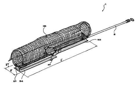
- Figure 16 shows a perspective view of a retaining device according to
the present
disclosure, in a non-operating configuration.
With reference to the figures, a retaining device according to the present
disclosure
is indicated by the reference number 1.
Said retaining device 1 may be used in different fields: for example it may be
used to
retain snow (so-called snow protection device), for protection against
avalanches
(so-called avalanche protection device), for stabilizing or retaining earth or
embankments (so-called stabilization device), for protection against falling
rocks (so-
called rockfall or landslide protection device), or for other similar uses.
In the embodiment shown, the retaining device 1 is a stabilization device, for
example able to be arranged on an unstable slope 91 of a mountain and fixed
there
in ways which will be described in greater detail below, so as to stop or
limit the
movement downhill of earth or rocks on the uphill side of the device 1.
The retaining device 1 comprises a retaining barrier 3 and a support strut 2
connected to the retaining barrier 3.
CA 02826740 2013-08-07
WO 2012/107896 PCT/1B2012/050588
6
In particular, when the retaining device 1 is installed on-site, the support
strut 2 and
the retaining member 3 are in a substantially T-shaped arrangement or
configuration, where the support strut 2 forms the core of the T and the
retaining
barrier 3 forms the flange of the T.
In the example, the retaining device 1 is installed on the ground 92 in the
configuration of an overturned T so that one side 3a, or bottom side, of the
retaining
barrier 3 rests on the ground 92 and forms a certain angle 13 with the ground
92. In
particular, the retaining barrier 3 may be arranged substantially
perpendicular to the
ground 92 or inclined downhill.
The support strut 2 acts as a prop or support for the retaining barrier 3 in
order to
prevent the latter from being able to be overturned or moved under the weight
of the
material to be retained.
The support strut 2 has a first end 21, or uphill end, which can be connected
to the
ground 92 via suitable fixing means, said fixing means for example comprising
a ring
25 attached to the first end 21 of the support strut 2 and a tie member 27
which
connects the ring 25 to an anchoring device (not shown) embedded in the ground
92. Fixing of the support strut 2 to the ground 92 allows the retaining device
1 to be
kept in a pre-chosen position. These fixing means may be formed in ways known
to
the person skilled in the art and consequently will not be further described.
For
further details, see for example Italian patent IT1288181 and European patent
application EP1921210.
A second end 22, or downhill end, of the support strut 22 is associated with
or
connected to the retaining barrier 3, in particular to a central region
thereof, in ways
described below.
In the example, as shown in particular in Figures 1 to 3, the retaining
barrier 3
comprises a support frame 4 and a retaining mesh 35 which is fixed to the
support
frame 4, for example by means of hooks 37.
The support frame 4 includes at least three arms 5 which are mounted on a
central
member 40 to which also the support strut 2 is connected.
In the example shown, the support frame 4 comprises four arms 5: two first
arms 51,
53 and two second arms 52, 54. Below, each of said arms will be indicated
generally
by the reference number 5 when it is not relevant whether it is a first arm or
a
second arm.
In an operating configuration of the support frame 4 (for example when the
retaining
device 1 is installed on-site) the arms 5 are splayed with respect to each
other: two
successive arms form an angle relative to each other. In other words, as shown
in
detail in Figures 3 and 6, the arms 5 in the operating configuration are
arranged
CA 02826740 2013-08-07
WO 2012/107896 PCT/M2012/050588
7
radially and extend from the central member 40 to which they are fixed. In the
operating radial configuration, each arm 5 is oriented along a respective
radial
direction 50a, 50b.
In particular, this radial arrangement is substantially flat: for example, the
arms 5 are
coplanar with each other (as visible for example in the top plan view of
Figure 2).
In the example shown, the first arms 51, 53 are aligned with each other and
the
second arms 52, 54, which are arranged on the opposite sides to the first arms
51,
53, are aligned with each other in the operating configuration. Basically, the
first
arms 51, 52 are arranged along a first diagonal 50a of the retaining barrier 3
and the
second arms 52, 54 are arranged along a second diagonal 50b of the retaining
barrier 3, so as to form an X or a Saint Andrew's cross. The central member 40
is
located in the region of intersection between the first diagonal 50a and the
second
diagonal 50b.
Said diagonals 50a, 50b correspond to the radial directions of the respective
first
arms 51, 53 and second arms 52, 54 in the radial configuration and also to
their
longitudinal central axes 50.
In the example, the first arms 51, 53 form an angle a of 80 degrees with the
second
arms 52, 54.
In particular, the support frame 4 has a substantially quadrangular shape, as
does
the retaining barrier 3.
The support frame 4 extends mainly along two dimensions, i.e. its overall
thickness
S is substantially smaller than its width L and its height H, these latter two
dimensions being substantially comparable to each other in terms of order of
magnitude. The support frame 4 defines a first face or side 31, or uphill
side, of the
retaining barrier 3, while the retaining mesh 35 is situated on a second face
or side
32, or downhill side, which is opposite to the first face 31.
The central member 40 comprises a first plate 41 and a second plate 42, which
are
arranged on opposite sides of the region of intersection between the first
diagonal
and the second diagonal of the retaining barrier 3, along the first face 31
and second
face 32, respectively. Therefore, the ends of the arms 5, in the region of the
central
member 40, are enclosed between the first plate 41 and the second plate 42.
Each arm 5 is fixed to the central member 40 by means of a respective pair of
bolts
45, 46. For this purpose, the central member 40 and each arm 5 comprise
respective first seats 47a, 47b and respective second seats 48a, 48b for
receiving
the bolts 45, 46. These seats 47a, 47b, 48a, 48b are basically through-holes
which
pass through the first plate 41, the arm 5 and the second plate 42.
For each arm, a first bolt 45 is inserted inside the first seats 47a, 47b and
clamped
CA 02826740 2013-08-07
WO 2012/107896 PCT/1B2012/050588
8
with a respective nut 451, while a second bolt 46 is inserted inside the
second seats
48a, 48b and clamped with a respective nut 461.
With respect to a longitudinal central axis 50 of the arm 5, the first seats
47a, 47b
are located on the opposite side to the second seats 48a, 48b. In the example,
each
plate 41, 42 is provided with eight through-holes, i.e. two through-holes
(first seat
47a and second seat 48a) for each arm 5. Each arm 5 is provided with two
through-
holes (first seat 47b and second seat 48b) which, when the arm 5 is in the
operating
position, are arranged matching the respective holes 47a, 48a in the plates
41, 42.
In the embodiment shown, the first arms 51, 53 form a single piece, i.e. are
successive parts or sections of a same beam 56 which passes through the
central
member 40; basically, the first arms 51, 53 are physically continuous with
each
other. The second arms 52, 54 are structurally independent of each other, i.e.
are
parts of beams which are discontinuous.
In particular, the arms 5 are formed by a beam with an I-shaped cross-section,
having a core 57a and two flanges 57b, 57c on opposite sides of the core 57a.
In the region of the central member 40, where the arms 5 converge together,
the
beam 56 which forms the two first arms 51, 53 has a notch or recess 58 formed
in a
first flange 57b and part of the core 57a.
The ends of the second arms 52, 54 in the region of the central member 40
(i.e. at
the intersection with the first arms 51, 53) have in turn an incision 59 in
the second
flange 57c and part of the core 57a. This allows the arms 5 to be arranged
coplanar
with each other so as to form a support frame 4 which is substantially flat
and has a
thickness S equal to the height H5 of the arms 5.
Moreover, by forming the recess 58 in the first flange 57b of the first arms
51, 53
and the incision 59 in the second flange 57c (i.e. in the flange opposite to
the first
flange 58b) of the second arms 52, 54, the first arms 51, 53 and the second
arms
52, 54 substantially complement each other in the intersection region.
Consequently, the overall contact area between each of the plates 41, 42 and
the
arms 5 is maximized, thus improving the solidity of the support frame 4 as a
whole.
The arms 5 may comprise reinforcing elements 57h which connect the first
flange
57b to the second flange 57c. The beam 56 may also comprise reinforcing
elements
57g which are fixed to the core 57a in the region of the recess 58. Similar
reinforcing
elements may be provided for the second arms 52, 54 in the region of the
incision
59.
Means 410 for performing connection to the support strut 2 are associated with
the
first plate 41, i.e. with the plate arranged on the uphill side 31 of the
retaining barrier
3. It should be noted that, in the example, the connection means 410 are
arranged
CA 02826740 2013-08-07
WO 2012/107896 PCT/1B2012/050588
9
substantially at a central point of the retaining barrier 3, i.e. at a point
defined by the
convergence of the arms 5, i.e. at the centre of the radial arrangement.
In order to allow the retaining barrier 3 to vary its inclination relative the
support strut
2, said connection means 410 comprise an articulated joint, such as a simple
hinge
(i.e. a cylindrical hinge) or a spherical hinge for example.
In the embodiment shown, the articulated joint 410 comprises a substantially
spherical element 411, which is fixed by means of welding to the first plate
41, and a
casing or shell 221 attached to the second end 22 of the support strut 2. The
shell
221 has a substantially C-shaped form and defines a cavity for receiving the
spherical element 411. A locking bolt 227 (or alternatively a peg) is also
provided,
being inserted transversely between the two sides of the C-shape through
special
holes 223 and passing in the vicinity of the first plate 41, in particular
inside a groove
between the latter and the spherical element 411. The locking bolt 227 thus
arranged prevents extraction of the support strut 2 from the spherical element
411.
A joint forming a spherical hinge with a multiple degree of freedom is thus
obtained,
allowing the support strut 2 to assume any spatial angle with respect to the
retaining
barrier 3 and to rotate about its longitudinal axis 200.
Moreover, the spherical element 411 includes a seat 415 for removably
receiving a
pin or bolt 229. In the example, this seat 415 is a hole passing through the
spherical
element 411 and having a longitudinal axis 418 substantially parallel to the
first plate
41. The shell 221 mounted on the support strut 2 has corresponding holes 225
for
allowing insertion of the pin 229.
Insertion of the pin 229 inside the seat 415 and inside the holes 225 allows
the
spherical hinge of the articulated joint 410 to be converted into a
cylindrical hinge,
i.e. into a joint with a single degree of freedom, where relative rotation of
the
retaining barrier 3 and the support strut 2 occurs only about the longitudinal
axis 418
of the seat 415.
Basically, the articulated joint 410 equipped with pin 229 inserted in the
seat 415 is a
cylindrical hinge, while the articulated joint 410 without the pin 229 is a
spherical
hinge.
The retaining device 1 comprises a plurality of tie members 15, each of which
connects a respective arm 5 to the support strut 2, in particular to the first
end 21 of
the latter. The retaining device 1 thus has overall a substantially pyramidal
shape,
as shown in Figure 1.
Moreover, a perimetral cable 38 is arranged along the perimeter of the
retaining
barrier 3, connecting together the peripheral ends of the arms 5; the
perimetral cable
38 acts as a support for the retaining mesh 35. The characteristics of the tie
CA 02826740 2013-08-07
WO 2012/107896 PCT/IB2012/050588
members 15, which are for example flexible elements, and of the perimetral
cable
38 may be regarded substantially as belonging to the prior art (see for
example
Italian patent IT1288181 and European patent application EP1921210).
In addition to the operating configuration described hitherto, the retaining
device 1
may also assume a non-operating configuration in which it has a smaller volume
and is easier to transport. In particular, the retaining device 1 is in this
non-operating
configuration before being installed, i.e. during manufacture, storage and
transportation of said retaining device 1; the retaining device 1 is in
operating
configuration during installation on-site.
In the non-operating configuration, shown in Figures 7, 15 and 16, the arms 5
are
substantially parallel to each other and the support frame 4 is in a closed
configuration: the support frame 4 and the retaining barrier 3 have a mainly
single-
dimensional extension. Differently from the operating configuration, their
height H' is
substantially less than their width L', while the thickness S' is unchanged
with
respect to the operating configuration.
This is possible owing to the fact that at least some of the arms 5 are
displaceable
relative to each other, so as to be arranged parallel instead of radially.
In the non-operating configuration (Figures 7 and 15) the arms 5 are
substantially
parallel to each other, while in the operating configuration (Figures 6 and
13) the
arms 5 are splayed apart in a radial configuration.
In other words, in the non-operating configuration at least one of the arms 5
(i.e. at
least a first arm 51, 53) is oriented along the same radial direction 50a as
in the
operating configuration, while the remainder of the arms 5 (i.e. the second
arms 52,
54) are oriented along a direction 50c which is substantially parallel to the
radial
direction 50a of said at least one of the arms 5.
In the embodiment shown, the second arms 52, 54 are movable relative to the
first
arms 51, 53 between a non-operating configuration and an operating
configuration.
The two first arms 51, 53 are fixed together, in the example being parts of
the same
beam 56.
The second arms 52, 54 are therefore movable or displaceable between the non-
operating configuration and the operating configuration; the first arms 51, 53
do not
vary their position between the non-operating configuration and the operating
configuration.
In the non-operating closed configuration, the first arms 51, 53 are oriented
along
the same radial direction 50a as in the operating radial configuration, while
the two
second arms 52, 54 are oriented along a direction 50c which is substantially
parallel
to the radial direction 50a of the two first arms 51, 53.
CA 02826740 2013-08-07
WO 2012/107896 PCT/IB2012/050588
11
In particular, in order to ensure that a second arm 52, 54 is movable, only
one of the
respective bolts 45, 46 (in the example, the first bolt 45) is inserted inside
the
respective seats (in the example, the first seats 47a, 47b) such that this
bolt 45 acts
as a pivot for rotation of the second arm 52, 54 with respect to the central
member
40 and with respect to the first arms 51, 53. Where necessary, in order to
allow
rotation, the nut 451 of the bolt 45 which acts as a pivot element must not be
fully
tightened. Alternatively, this pivot element may be replaced by a peg, a bolt
or other
member suitable for acting as a pivot.
The second bolt 46 will be inserted inside the respective second seats 48a,
48b
during installation on-site of the retaining device 1.
Basically, the second arms 52, 54 are pivotably hinged on the central member
40;
therefore they are configured to rotate with respect to the central member 40
so as
to perform an angular displacement between the non-operating closed
configuration
and the operating radial configuration. In other words, the movement of the
second
arms 52, 54 between the non-operating configuration and the operating
configuration (and vice versa) is a pivoting rotation relative to the central
member
40.
Since the first seats 47a, 47b and the pivoting bolt 45 extend substantially
perpendicular to the plates 41, 42 and to the surface of the retaining barrier
3, the
hinging axis 450 of the respective second arm 52, 54 is also substantially
perpendicular to the plates 41, 42 and to the plane of the radial
configuration.
The rotation of the second arm 52, 54 therefore occurs towards a first arm 51,
53
without coming out of the plane of the support frame; in other words, the
movement
of the second arm 52, 54 between the non-operating closed configuration and
the
operating radial configuration is an angular displacement which occurs in the
plane
of the radial arrangement, i.e. is coplanar with the radial configuration.
The parallel-arm arrangement which the arms 5 assume in the non-operating
configuration (or closed configuration) is therefore substantially coplanar
with the
radial arrangement (or open configuration) which the arms 5 assume in the
operating configuration.
In the case of the embodiment shown, in the non-operating configuration the
second
arms 52, 54 are each adjacent to a respective first arm 51, 53 and the second
arms
52, 54 extend on the opposite sides of the central member 40.
Basically, during the movement from the non-operating configuration to the
operating configuration (or vice versa), the second arms 52, 54 are rotated
both in
the same direction (in the anti-clockwise direction in Figure 7 and in the
clockwise
direction in Figure 6).
CA 02826740 2013-08-07
WO 2012/107896 PCT/1B2012/050588
12
The first seat 47a, 47b in which the pivoting bolt 45 is located is that
closest to the
first arm 51, 53 towards which the second arm 52, 54 is displaced in the non-
operating configuration.
In the non-operating configuration, the first seat 47b (or hinging seat) of
the second
arm 52, 54 is at a distance D1 from the respective adjacent first arm 51, 53
which is
less than the distance D2 of the second seat 48b (or locking seat) from the
same
first arm 51, 53.
Owing to this special feature and suitable shaping of the notch 58 and the
recess
59, the second arm 52, 54 does not interfere with the first arms 51, 53 during
the
angular displacement between the two configurations, i.e. closed configuration
and
open configuration.
Moreover, the first seats 47a, 47b are situated outside the profile of the
first arms
51, 53 and at a distance D1 from this profile. The distance D1 is chosen with
a
suitable value so that, in the non-operating configuration, the distance D5
between
the second arm 52, 54 and the respective adjacent first arm 51, 53 is at a
given -
possibly small - value so that the height H' of the support frame 4 is
minimal.
The support strut 2 is movable with respect to the retaining barrier 3. In
particular,
the support strut 2 is movable between a first angular position and a second
angular
position.
In the first angular position, which is assumed in particular when the
retaining device
1 is installed (therefore corresponding to the operating radial configuration
of the
support frame 4), the support strut 2 and the retaining barrier 3 are in the
said T-
shaped configuration, as shown in Figures 1 to 5.
In the second angular position, which in particular is assumed during storage
and/or
transportation of the retaining device 1 (therefore corresponding to the non-
operating closed configuration of the support frame 4), the support strut 2 is
rotated
towards the retaining barrier 3 and in particular is substantially parallel to
the radial
direction 50a of the first arms 51, 52, i.e. to the arms 5 in the non-
operating
configuration, as shown in Figures 14 to 16.
The overall volume of the retaining device 1 in the non-operating
configuration is
therefore very compact, because the arms 5 and the support strut 2 are
parallel to
each other and close together.
In the embodiment shown, the support strut 2 in the second operating position
is
parallel to the first arms 51, 53.
In particular, the seat 415 in the spherical element 411 is formed so that its
longitudinal axis 418 is parallel to the retaining barrier 3 and at right
angles to the
radial direction 50a of the first arms 51, 53.
CA 02826740 2013-08-07
WO 2012/107896 PCT/1B2012/050588
13
When the pin 229 is inserted inside the seat 415 (and the locking bolt 227 is
removed from the holes 223), the articulated joint 410 acts as a cylindrical
hinge and
limits the movement of the support strut 2 to an angular displacement between
the
first angular position and the second angular position, i.e. in a plane at
right angles
to the retaining barrier 3 and parallel to the first arms 51, 53.
As a result, the support strut 2 remains coplanar with the first arms 51, 53,
ensuring
the compactness of the retaining device 1 during transportation and preventing
undesirable and dangerous movements of the support strut 2 outside of this
plane
during installation.
The retaining device 1 is supplied in the non-operating configuration, with
the arms 5
parallel in the closed configuration and the support strut 2 in the second
angular
position, i.e. parallel to the arms 5 (Figures 15 and 16). The pin 229 is
inserted
inside the seat 415; the second bolts 46 for the second arms 52, 54 and the
locking
bolt 227 are not mounted on the retaining device 1 or in any case are not
operative.
The retaining mesh 35 is connected to only the first arms 51, 53 and is folded
up so
as to reduce its volume, or alternatively is supplied separately.
The retaining device 1 in the non-operating configuration is transported to
the
installation site. Owing to its compact and elongated shape which the device
assumes in this configuration, transportation is easier than in the case of
the known
devices.
At the installation site, the arms 5 are splayed apart, arranging them in the
operating
radial configuration. In the example shown, both the second arms 52, 54 are
displaced into the operating configuration.
The second bolts 46 are inserted and fixed inside the second seats 48a, 48b so
as
to lock the second arms 52, 54 in the operating configuration.
The second bolts 46 therefore form part of the locking means for locking the
second
arms 52, 54 on the central member 40 and preventing shape variations of the
support frame 4 in the operating configuration.
The retaining mesh 35 is extended and fixed to the support frame 4.
The support strut 2 is brought into the first angular position, restoring the
T-shaped
configuration. The locking bolt 227 is inserted inside the holes 223 so as to
prevent
extraction of the support strut 2 from the spherical element 411. The
retaining device
1 is fixed to the ground using the known methods. The pin 229 is removed from
the
seat 415, so that the functionality of the spherical joint 410 is restored.
Should it subsequently be required to remove the retaining device 1 (for
example for
maintenance or replacement purposes), the abovementioned steps may be
performed in the reverse order so that the retaining device 1 assumes again
the
CA 02826740 2013-08-07
WO 2012/107896 PCT/1B2012/050588
14
non-operating closed condition, ready for transportation.
In the embodiment described, the first seats 47a, 47b and the second seats
48a,
48b are identical to each other and likewise the first bolts 45 and the second
bolts
46 are identical to each other. The method of manufacturing the retaining
device 1 is
simple because it is not required to form these seats in a different manner
depending on their function. In the case of the second arms 52, 54, each of
said
seats may be used as a locking or hinging seat.
Similarly, a bolt may be used equally well as a pivot element 45 or as a
locking
element 46, without having to provide two different types of elements.
As an alternative to the bolts, the pivot elements 45 and the locking elements
46
may be pegs, keys or similar elements.
The retaining device 1, in particular the support strut 2, the arms 5 and the
central
member 40, are for example made of galvanized steel.
The retaining device 1 described here may be subject to numerous variations
and
modifications.
For example, the first arms 51, 53 made as one piece may be welded directly
onto
the central member 40, instead of being bolted. In this case, the bolts 45, 46
and the
respective seats 47a, 47b, 48a, 48b are not required for the first arms 51,
53.
For example, the first arms 51, 53 may be structurally independent of each
other,
instead of being made as one piece, and optionally may be movable relative to
each
other so as to be displaced into the non-operating configuration.
For example, the support frame may comprise a greater number of arms (for
example six arms) suitably arranged radially in the operating configuration
and
movable towards a parallel-arm arrangement in the non-operating configuration.
For example, the support frame may comprise only three arms, one or two of
which
are movable with respect to a first arm (for example by means of a hinging
system)
so as to assume a parallel-arm arrangement in the non-operating configuration
and
a radial arrangement in the operating configuration.
The subject of the present disclosure has been described hitherto with
reference to
preferred embodiments thereof. It is understood that other embodiments
relating to
the same inventive idea may exist, all of these falling within the scope of
protection
of the claims which are provided hereinbelow.