Note: Descriptions are shown in the official language in which they were submitted.
CA 02827041 2013-09-12
1
DYNAMIC SHOULDER ORTHOSIS WITH REHABILITATING ADDUCTION
FIELD OF THE INVENTION
The present invention relates to shoulder orthosis for supporting the arm in
abduction
after a surgical repair of tear injuries to the rotator cuff, and more
specifically to shoulder orthosis
with adjustable arm stabilisation height enabling cyclical exercising of the
uninjured arm adductor
muscles.
BACKGROUND OF THE INVENTION
Muscle tears are degenerative type bodily injuries, whose occurrence increase
with old
age, in particular beyond 70 to 80 years of age. Shoulder muscle tear injuries
occur typically when
a person repetitively lifts heavy loads above his/her head, and will appear
regularly in activities
such as swimming, window cleaning, freight handling, strength conditioning
exercising, and the
like.
It often happens that an important part of the medical treatment of a repaired
shoulder
muscle requires the stabilization and support of the arm in abduction (away
from the patient's
sagittal plane) during the rehabilitation healing period which typically lasts
between four to twelve
weeks, and in general about six weeks. Shoulder muscular injuries can be of
different types
involving different set of muscles. Different medical treatments involving
surgery may be required
depending on the injury type and severity. In each case, proper healing
requires that the patient's
arm be stabilized at a specific angle relative to the body to maintain the
shoulder in the ideal
position. As the healing progresses, the arm stabilization angle is often
reduced, bringing the arm
in adduction (closer to the patient's sagittal plane) i.e. gradually closer to
its natural position along
the body. Furthermore, these injuries typically affect only part of the
muscles of the shoulder,
often being the supraspinatus (with possibly the infraspinatus) muscle with
muscle tear length
varying usually between 1 and 20 mm.
After an initial healing period, treatments exercising of the uninjured
healthy muscles of
the shoulder ¨ including the pectoralis major muscle, and possibly the
latissimus dorsi muscle ¨ are
CA 02827041 2013-09-12
t
2
recommended to maintain tonus of these healthy muscles. This exercising is
limited to a certain set
of movements that minimize the use of the injured or repaired muscles. For
example, in many
types of injuries to the rotator cuff, it is recommended after a certain
healing period for the patient
to repeatedly exercise his/her adduction muscles.
Many of the shoulder orthosis and arm stabilization apparatuses known in the
art are
used to stabilize the arm in a single static given position. Others offer
adjustment mechanisms
enabling to change the height at which the arm is stabilized. But these height
adjustment
mechanisms often require external intervention and cannot be operated unaided
by the patient
alone. Some also require complex or lengthy procedures, requiring the orthosis
to be firstly
removed, or involving spare parts and even special tools. Some also comprise
unstable harnesses
and splint, or they comprise multiple support structures which are often
cumbersome and
uncomfortable. Furthermore, most of these orthosis do not enable any kind of
free arm movement
by the patient's arm, which is a major inconvenience when several weeks of
rehabilitation are
required.
Furthermore orthosis known in the art do not allow for the concurrent
flexion/extension
of the forearm around the injured arm elbow.
SUMMARY OF THE INVENTION
The present invention relates to a shoulder orthosis for surgically repaired
rotator cuffs,
and more specifically to surgically repaired rotator cuff muscles following
tear of the supraspinatus
muscle group only or to the supraspinatus and infraspinatus muscles. The
present shoulder
orthosis enables the exercising of the patient's arm healthy adduction muscles
of the arm while
minimizing contraction and stress of the injured muscles in the rotator cuff.
The present shoulder
orthosis also enables the flexion/extension of the forearm around the elbow
while keeping the arm
generally horizontal at a constant height. The present shoulder also
stabilizes the arm at different
angle relative to the body nature, severity and level of healing of the
injury.
The flexion/extension of the elbow without displacement of the arm, since the
elbow is
coaxial to the piston, allows the activation of the elbow flexors/extensors
(biceps and triceps), and
also to be more functional and enabling the forearm to come closer to the
patient's body. This will
CA 02827041 2013-09-12
3
3
facilitate daily activities, such as coming across a narrow door frame,
donning and wearing a coat,
and drawing bedsheets over the patient's body when sleeping. The orthosis
enables movement of
the shoulder and of the elbow, to prevent "frozen shoulder" syndrome and
stiffness in the joints.
Generally speaking, the present invention relates to a shoulder orthosis for
long term
support of a patient's arm in postoperative shoulder immobilization posture
for rotator cuff tears,
comprising a waist belt, an arcuate forearm support, and a piston and cylinder
assembly
interconnecting the waist belt to the forearm support and biasing the forearm
support to an upper
limit position. The orthosis provides stable support of the forearm about a
horizontal plane, while
enabling both pivotal movement of the arm about a vertical axis intersecting
the patient's elbow
and towards or away from the patient's torso within this horizontal plane.
This orthosis also
enables cyclical up and down motion of the forearm support, the downward
motion healthy
adductor- assisted against the bias of the piston and cylinder assembly. A
lock system releasably
locks the piston and cylinder at a selected retracted condition of the piston
rod.
In particular, the present invention is directed at a shoulder orthosis for
long term support
of a patient's arm in postoperative shoulder immobilization abduction posture
for injured rotator
cuff muscle tear, said orthosis comprising: a waist belt member, releasably
adjustably attachable
to the patient's waist line; an arm splint, defining opposite outer and inner
end portions and
releasably adjustably attachable to the patient's arm; an extendible connector
member, spacedly
interconnecting a support section of said belt member to said splint inner end
portion and defining
a lengthwise axis thereof, wherein said splint is movable between a fully
extended abduction first
limit condition and a retracted adduction second limit condition, angularly
relative to the patient's
torso; damper means, cooperating with said connector member in biasing said
splint away from
said belt member, wherein said damper means enables cyclical back and forth
extension/retraction
of said extendible connector member between said first and second limit
conditions thereof;
locking means, releasably locking said extendible connector member at a
selected condition
against the biasing force of said damper means; and splint swing motion
compensating means,
providing transverse play of said connector member transversely of said
lengthwise axis thereof, to
accommodate inward rotation of the patient's arm naturally induced as the
patient's arm is raised
CA 02827041 2013-09-12
4
away from the patient's torso; wherein said orthosis enables cyclical
exercising of the patient's arm
healthy adduction muscles while minimising contraction of the injured muscles
in the rotator cuff.
In one embodiment, said swing motion compensating means consists of a rotating
member, integral to said connector member and enabling rotation of said splint
relative to said
connector member lengthwise axis, wherein said splint outer end portion is
movable radially away
from or towards the patient's torso.
In one embodiment, said damper means consists of an assembly made of a piston
rod
axially engaging a cylinder, said assembly integral to said extendible
connector member, and of
means continuously biasing said piston rod in extended condition away from
said cylinder, said
cylinder defining an outer end portion opposite said piston, and said piston
rod defining a head
opposition said cylinder. Said damper means could consist of a gas spring
unit.
In one embodiment, said locking means consists of an elastic locking unit,
cooperating
with said gas spring unit, and a control member, controlling actuation of said
locking means.
In one embodiment, said splint consists of: a channel member defining an
arcuate panel,
sized and shaped to conformingly receive and support a lower half portion of a
patient's forearm,
said arcuate panel having an inner end portion and an outer end portion, and a
bed extending
therebetween; forearm securing band members, integrally mounted to said
arcuate panel
intermediate said inner and outer end portions thereof and releasably
engageable around an
upper half portion of the patient's forearm; and a support anchor, integrally
mounted transversely
of said arcuate panel inner end portion and endwisely of said cylinder outer
end portion. Said
rotating member could consist of said piston rod being freely rotatably
mounted axially within said
cylinder. During the patient's arm flexion and extension back and forth
radially relative to the
patient's torso within the same horizontal plane, the pivotal axis of the
patient's elbow remains
coaxial at all times with the lengthwise axis of said piston rod and cylinder
assembly.
In one embodiment, said belt member support section consists of an inner
portion,
shaped and sized to conformingly fit around the patient's trochanter portion,
an integral outer
pocket portion defining a pocket having a mouth, said piston rod head engaging
through said
pocket mouth and into said pocket, and a pivot mount member pivotally mounting
said piston rod
head to said pocket portion into said pocket and providing pivotal motion of
said piston rod head
CA 02827041 2013-09-12
N
r
about an axis transverse to said piston and cylinder assembly lengthwise axis.
Said locking means
control member could be mounted remotely from said piston and cylinder
assembly, for example
onto said belt member at a distance from said belt member support section.
In one embodiment, said forearm securing band members include adjustable hook
and
5 loop fastener means. Said waist belt member could also include adjustable
hook and loop fastener
means.
In one embodiment, there is further provided a palm rest tab, integrally
projecting from
said arcuate panel outer end portion, for supporting the patient's hand palm,
said tab preferably
having aeration bores, and being slightly transversely inclined and making a
large acute angle
relative to said arcuate panel bed, wherein the patient's arm wrist is
maintained in slight
extension.
Cushioning members could be carried inwardly of said belt member and
ergonomically
conforming to the patient's hip.
In one embodiment, during arm flexion and extension back and forth radially
relative to
the patient's torso, the pivotal axis of the patient's elbow remains coaxial
at all times with the
lengthwise axis of said piston rod and cylinder assembly.
In one embodiment, said arcuate panel inner end portion is of such a shape as
to provide
both a lateral support and an anteroposterior support for the patient's
supported forearm.
The invention also relates to a method of use of a shoulder orthosis, said
method
comprising the following steps: attaching said waist belt to the patient's
waist; securing the
patient's arm to said arm splint; deactivating said locking means; and
engaging the patient's
adductor muscles to at least partly retract said connector member from said
fully extended first
limit condition towards said second limit condition thereof.
In one embodiment, the method also includes the steps of: releasing the
patient's
adductor muscle engagement; and allowing said damper means to extend said
connector member
to return to its said first fully extended limit condition.
In one embodiment, the method also includes the step of engaging once again
the
patient's adductor muscles to retract said connector member from said fully
extended first limit
condition towards its said second limit condition.
CA 02827041 2013-09-12
i
6
In one embodiment, the method also includes the step of rotating said arm
support
channel member relative to said waist belt member about said connector member,
wherein flexion
and extension of the patient's arm back and forth radially relative to the
patient's torso is
achieved, and wherein the pivotal axis of the patient's elbow remains coaxial
at all times with the
lengthwise axis of said connector member.
DESCRIPTION OF THE DRAWINGS
In the annexed drawings:
- Figure 1 is an elevational view of a patient in phantom lines, wearing a
shoulder orthosis
according to a preferred embodiment of the present invention, with the forearm
splint in a
partly retracted adduction condition;
- Figure 2 is a view similar to figure 1, but with the forearm splint in an
extended abduction
condition;
- Figure 3 is an enlarged front perspective view of the shoulder orthosis
of figure 1 taken from a
slightly elevated viewpoint;
- Figure 4 is an elevational view of the shoulder orthosis of figure 1
showing the support member
at a wide angle relative to the belt;
- Figure 5 is an enlarged view similar to figure 2, but without the patient's
outline and showing
the connector member in abduction;
- Figure 6 is a top view of the shoulder orthosis of figure 5, with the
forearm splint's free outer
portion radially located away from the belt in extended condition of the
patient's arm;
- Figure 7 is a view similar to figure 6, but with the forearm splint free
outer portion pivoted
radially closer towards the belt in flexed condition of the patient's arm
about the same
horizontal plane as in figure 6;
- Figures 8 and 9 are views similar to figures 6 and 7, respectively, but
further showing a patient
in phantom lines;
CA 02827041 2013-09-12
7
- Figure 10 is a view similar to figure 5 but with the piston rod being
retracted in adduction
condition and also showing a transversal cross-sectional view of the shoulder
orthosis of figure 4
taken at midpoint between the front and the back of the belt and connector
member;
- Figure 11 is an enlarged view of the area circumscribed in circle 11 of
figure 10, illustrating how
the hip anchor attaches to both connector member and to the belt;
- Figure 12 is an enlarged view of the area circumscribed in circle 212
of figure 10, illustrating how
the forearm splint is attached to the extendible connector member;
- Figure 13 is a cut away enlarged perspective view of the piston and cylinder
actuator of the
shoulder orthosis of figure 4, showing how the piston yoke member is
operatively connected to
a remote control knob; and
- Figure 14 is an enlarged partly broken sectional view of the components
of figure 13.
DETAILED DESCRIPTION OF THE EMBODIMENTS
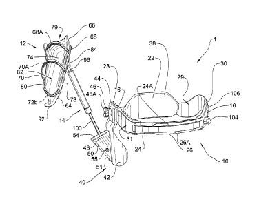
Referring to accompanying figures 1-14, there is shown a shoulder orthosis 1
according to
a preferred embodiment of the present invention. Shoulder orthosis 1 comprises
a waist harness
10, a forearm splint 12, and an extendible connector member 14 interconnecting
harness 10 and
splint 12.
Referring more specifically to figures 3-5 and 10, waist harness 10 comprises
a waist belt
16 having the general aspect of a strip made out of a fairly stiff yet
extensible, semi-flexible and
resilient material. Waist belt 16 is sized and shaped as to conformingly fit
about the patient's waist
adjustably to various waist lines. Waist belt 16 defines a baseline 20, a back
section 22, first and
second frontal sections 24, 26 each of which opposite back section 22, first
and second hip sections
28, 30 opposite each other, an interior face 29 being the lateral section of
waist belt 10 in contact
with the patient, and an exterior face 31 opposite inner face 29. Hook and
loop fastener band
members 24A, 26A releasably adjustably interconnect waist flap sections 24,
26, respectively. Back
section 22 is wider than the other sections of waist belt 16 and shaped to
match the patient's back,
to offer firm yet comfortable support. First and second hip sections 28, 30
deviate upwardly from
baseline 20 so that they can rest fittingly over the patient hips, once again
to provide firm yet
CA 02827041 2013-09-12
8
comfortable support. Waist belt 16 can be flexed and stretched from a closed
position, in which
first and second frontal sections engage in partly overlapping fashion, and
become releasably
interlocked by adjustable hook and look fastener band members 24A, 26A, to an
open position in
which first and second frontal sections are spaced apart and clear one
another, thus enabling the
patient to either put belt 20 around its waist or remove same. Once around the
patient waist,
waist belt 20 can be stretched in place as to offer firm support.
Inner face 29 of waist belt 10 is lined with .a belt padding 38 as to provide
additional
comfort when waist belt 10 is secured about the patient's waist. Belt padding
38 is preferably
made out of a cushiony non-absorbent material, for example a 20 Shore hardness
foam or a
PODIALENE foam, that can be kept in place even when shoulder orthosis 1 is
used in wet
conditions, as when the patient takes his/her shower. Waist belt 16, being
fairly stiff and shaped as
to retain the natural form of the waist, will help in maintaining waist
harness 10 firmly in place
once installed on the patient. This insures that the patient arms will stay
put in the postoperative
shoulder immobilization posture, and not move forward or backward, even after
long hours of
wearing orthosis 1.
Waist harness 10 also comprises a hip anchor 40 for receiving extendible
connector
member 14. Hip anchor 40 is symmetrical to and can be installed on either one
of first and second
hip sections 28, 30 of waist belt 16. Hip anchor 40 comprises a hip brace 42
that extends mostly
below baseline 20, and is shaped and sized to fit the lateral registering
trochanter portion R of the
patient's hip, for stable tilt-free transfer thereto of the combined weight of
the patient's arm,
forearm splint 12 and extendible connector member 14 as explained in more
details later on. Hip
anchor 40 also comprises a belt clip 44 extending above baseline 20 and shaped
to overlap fittingly
either one of first and second hip sections 28, 30 of waist belt 16. Belt clip
44 is equipped with a
belt lock button 46, which is a movable handle located over belt clip 44 that
can be turned
clockwise or counter clockwise to drive a set screw 46A respectively in and
out of waist belt 16 as
to respectively secure hip anchor 40 on waist belt 16 and release hip anchor
40 therefrom. Finally,
hip anchor 40 comprises a yoke member stand 48 extending orthogonally from hip
brace 42. Stand
48 comprises first and second triangular walls 50, 52 opposite each other and
extending from hip
brace 42, and a side wall 51 linking first and second walls 50, 52 on the side
opposite to hip brace
CA 02827041 2013-09-12
,
9
42. First and second walls 50, 52, side wall 51 and hip brace 42 combine to
form an open enclosure
or pocket 54. A shaft 55 extends through walls 50, 52, thus traversing pocket
54, and is used to
pivotally secure the lower end of support member 14 inside pocket 54, as
explained in more details
hereafter.
Still referring to figures 3-5 and 10, forearm splint 12 comprises a forearm
support 62, an
outer end hand support 64, a forearm padding 66, and forearm fixation loop
straps 68, 70.
Forearm padding 66 may include for example an elastomeric compound, such as
NEOPRENE . The
arcuate shape of forearm support 62 provides both a lateral support and antero-
posterior support
for the supported forearm. In this way, the supported arm will remain in place
into the forearm
support 62, even when the patient's body is laterally or rearwardly inclined.
This will be
particularly advantageous in the patient's everyday life, for example when the
patient's lays on
his/her bed, takes a bath/shower, eats a meal, .... Moreover, the symmetrical
shape of the
forearm support will readily adapt itself to any of the left or right arm, as
the case may be.
The loop circumference of each strap band 68, 70, can be adjusted in length by
providing
hook and look fasteners 68A, 70A, at opposite ends thereof.
In one embodiment, forearm support 62 is made from an elongated piece made out
of a
rigid yet lightweight moldable material such as polyvinyl chloride (PVC), and
defines opposite first
inner end 72a and second outer end 72b. Forearm support 62 comprises an inner
forearm bed 74,
extending all the way between first and second ends 72a, 72b. Forearm bed 74
is generally arcuate
or cross-sectionally U-shaped along its cross-section, and thus defines a base
77 and two lateral
walls 78, 80 which all combine to form an inward forearm channel 82 suitable
to receive the
patient's forearm, with the patient elbow located near first end 72a and with
the patient's wrist
located near second end 72b of forearm support 62. Furthermore, lateral walls
78, 80 are joined
together at first end 72a to form a transversely raised rounded back wall 79
in order to offer rear
support for the patient's elbow, thus stabilizing the arm and preventing the
elbow to accidently
slide rearwardly when placed in forearm channel 82, while maintaining the
elbow rotating axis
coaxial with the rotating axis of the present orthosis, as will be explained
hereinbelow. Forearm
channel 82 remains open at second end 72b, allowing the patient's wrist and
hand to extend
outwardly therethrough. Forearm support 62 also comprises an upper support
anchor 84, being a
CA 02827041 2013-09-12
protrusion extending from forearm support 62 near first end 72a on the
opposite side of forearm
bed 74.
As shown in figure 12, upper support anchor 84 has the general aspect of a
conical
protrusion with a truncated base 86 opposite forearm bed 74. Truncated base 86
is pierced with a
5
threaded bore hole 88 used to secure the upper end of support member 14, as
explained in more
details later on.
As shown in figures 1-5 and 10, fixation straps 68, 70 are installed crosswise
around
forearm support 62 respectively near first and second ends 72a, 72b. Fixation
straps 68, 70 are
stretched around forearm support 62 and the patient's forearm so as to secure
the latter in
10
forearm channel 82. The combination of fixation straps 68, 70 together with
lateral walls 78, 80
and back wall 79 enables the patient forearm to stay firmly in place and thus
ensures that the
shoulder is not being submitted to arm lifting loads as the patient leans
back, forward, and
sideways, or when the patient is lying in bed.
In another embodiment of the invention, fixation straps 68, 70 straps are
integral parts of
forearm padding 66, each one having a fixed end on one side of forearm padding
66, and a loose
end that is first stretched over the patient's forearm and then under the
splint, to be finally
attached over itself using fasteners such as hook and loop fastener strips
68A, 70A.
Forearm support 62 is lined with forearm padding 66 so as to increase comfort
for the
patient's forearm. Forearm padding 66 is shaped as to match forearm bed 74,
extending slightly
above lateral walls 78, 80, and more importantly near back wall 79, which
increases the overall tilt-
free stability of the patient's forearm in forearm bed 74. Said forearm
padding 66 is preferably
made out of a cushiony non-absorbent material that can be kept in place when
shoulder orthosis 1
is used in wet conditions. Finally forearm padding 66 being opened upwardly
ensures natural
ventilation as to maintain a comfortable temperature of the forearm.
Still referring to figures 3-5 and 10, hand support 64 is fixed to forearm
channel 82 on the
opposite side of forearm bed 74 near second end 72b, and extends lengthwise
outwardly
therefrom. Hand support 64 is an elongated plate defining a fixed end shaped
to overlap forearm
64 on the attachment location, and a loose end opposite fixed end, being a
palm rest tab 92. Hand
support 64 is made from a stiff yet extensible material. Palm rest tab 92 can
thus be adjustably
CA 02827041 2013-09-12
s
11
extended to accommodate patients with various arm lengths. A semi-flexible
connection of palm
rest 92 with hand support 64 allows palm rest tab 92 to twist sideways, e.g.
by up to 20 * on each
side, to accommodate supination and pronation motions occurring when the
patient's moves his
arm. Palm rest tab 92 is slightly transversely inclined relative to the plane
of base 77 of forearm
support 62 as to maintain the patient's wrist in slight extension. This
thereby reduces the pressure
in the carpal tunnel as to avoid adverse side effects related to carpal tunnel
syndrome. Palm rest
tab 92 may be pierced with a number of aeration bores 92A to let air flow
therethrough, thus
reducing discomfort caused by sweat.
Referring now to figure 13 and 14, there is shown a support member 14 being a
gas spring
with elastic locking as can be commonly found in the industry, such as the
"Bloc-O-Lift with Elastic
Locking" from the "Stabilus Inc." company. Elastic locking offers comfortable
damping when a
force is applied on both ends of the hydraulic cylinder and is thus best
suited for human
interaction. Connector member 14 comprises a generally elongated gas spring 15
extending from a
first cylinder end 94a to a second piston end 94b, opposite first end 94a.
Starting from first end
94a, gas spring 15 comprises in turn a cap screw 96, a cylinder barrel 98, a
piston rod 100 and an
outer piston head yoke base 102. Barrel 98 is an elongated hollow cylinder
comprising a pressure
chamber 118, a barrel cap 108 on one end, and a barrel head 110 on opposite
end. Barrel head 110
is pierced in its center as to allow piston rod 100 to move lenghtwisely
therethrough. Piston rod
100 also rotates freely relative to barrel 98. Piston rod 100 comprises a
first inner end 100a fixed to
an inner piston head 116 mounted inside barrel 98, and a second opposite outer
threaded end
100b fixed to yoke base 102 using a screw bolt 126.
As shown in figures 10-14, first threaded end portion 94a of cylinder 98 is
fixed to upper
anchor 84 of forearm splint 12 by inserting and screwing cap screw 96 into
bore hole 88. Cap screw
96 is a simple bolt screw welded on atop barrel cap 108. As illustrated in
figure 11, second end 94b
of support member 14 is pivotally mounted to stand 48 of hip anchor 40 about
pivot shaft 55,
which passes through a fixation hole 114 in base 102.
Connector member 14 also comprises a manual (hand or foot activated) actuation
mechanism 17 enabling to put gas spring 15 in either a locked state, in which
the condition of
piston 116 is fixed relative to barrel 98, or in an unlocked state, in which
piston 116 can
CA 02827041 2013-09-12
, =
12
extend/retract in barrel 98 between barrel cap 108 and barrel head 110 in
order to either
accumulate pressure in or release pressure from pressure chamber 118.
Actuation mechanism 17
comprises an actuator rod 122, which is an elongated shaft passing through
piston rod 100 and
piston 116, through both of which it can move longitudinally. Actuator rod 122
defines a first end
122a connected to an actuator valve 120 atop piston 116, and a second end 122b
connected to an
actuator tappet 124 inside yoke base 102. Piston 116 comprises a vent 113
allowing gas exchange
between the two sections of pressure chamber 118 on each side of piston 116
when valve 120 is
opened. Second end 122b of actuator rod 122 extends longitudinally beyond
second end 100a of
piston rod 100, thus leaving space between tappet 124 and piston rod 100 for
spring loaded
actuator coil 130, which is placed therebetween and around actuator rod 122.
Actuator
mechanism 17 also comprises a lever 112, defining a first end portion 112a,
and a second end
portion 112b opposite first end 112a. Lever 112 is pivotally carried by base
102 using a transverse
pivotal shaft 128 near its first end 112a. Second end portion 112b of lever
112 extends throughout
and beyond of one side of base 102 through a lever opening 117 made in base
102, thereby
allowing second end portion 112b of lever 112 to translate during pivotal
action about shaft 128 of
lever 112. Lever 112 is placed as to lean against actuator tappet 124 in order
to push or be pushed
by the latter. Actuator mechanism 17 also comprises a Bowden cable 106 passing
through a
Bowden cable guide 103 fixed to base 102 spacedly over lever 106. Bowden cable
106 defines a
first end 106a connected to lever 112 near second end portion 112b, and at a
second end 106b
connected to an actuator button 104 at a distance from cylinder 15. Actuator
button 104 may be
fixed on either one of waist belt hip sections 28, 30 being opposite to hip
anchor 40, with Bowden
cable 106 running for example along back section 22 of waist harness 10.
Actuator button 104 is
thus easily accessible manually by the patient on his/her uninjured side, for
operation of support
member 14.
When button 104 is pressed, Bowden cable 106 exerts a pull force on lever 112,
which in
turn pushes actuator tappet 124, actuator rod 122 and actuator valve 120. This
results in coil 130
being compressed and actuation valve 120 being lifted above piston 116. Vent
133 is thus opened
and gas spring 15 is put in its unlocked state. When button 104 is released,
so is the pull force of
Bowden cable 106 on lever 112. Coil 130 being resilient can then expand to
regain its initial form,
CA 02827041 2013-09-12
13
thereby pushing lever 106 away from Bowden cable guide 117, and thereby
closing actuator valve
120 through the intermediary action of actuator rod 122. Vent 113 is thus
closed and gas spring 15
returns to its locked state.
When gas spring 15 is in the locked state, it acts as a simple support
structure with
damping effect. When gas spring 15 is in the unlocked state, pressure can be
accumulated inside
pressure chamber 118 by retracting piston rod 100 into cylinder 98, i.e. by
applying an inward force
between first and second ends 94a, 94b of gas spring 15, thereby axially
moving piston 116 from a
first condition closest to barrel head 110 where gas spring 15 is said to be
expanded, to a second
condition closest to barrel cap 108 where gas spring 15 is said to be a fully
retracted. Gas spring 15
is said to be a partially retracted when piston 116 is located anywhere in
between said first and
second positions. When gas spring 15 is brought to its partially or fully
retracted condition, e.g.
upon adduction movement bringing the arm closer to the sagittal plane of the
patient's body,
when the patient's arm applies a retracting load on support member 14 mainly
with his/her
healthy pectoralis major and latissimus doris muscle, the pressure accumulated
in pressure
chamber 118 tends to return gas spring 15 to its expanded state by pushing
piston 116 to its first
position closest to barrel head 110. So whenever the inward force applied
between first and
second ends 94a, 94b of gas spring 15 is smaller than the outward force
exerted on piston 116 by
the pressure accumulated in pressure chamber 118, gas spring 15 naturally
expands towards its
expanded state, wherein abduction movement brings the arm away from the
sagittal plane of the
patient's body.
In another embodiment of the present invention, gas spring 15 is replaced by a
mechanical coil spring with similar properties. Other types of damper means
are not excluded
from the scope of the present invention.
In use, shoulder orthosis 1 comes preassembled with connector member 14
already fixed
to forearm splint 12 and hip anchor 40, as explained previously. Connector
member 14 is then
fixed to either one of first and second hip sections 28, 30 of waist belt 16
located on the side of the
patient's injured elbow using belt lock button 46. Actuator button 104 is then
placed on either one
of hip sections 28, 30 on the opposite side of hip anchor 40, with Bowden
cable 106 running along
back section 22. Waist belt 16 is then placed about the patient's waist, with
hip sections 28, 30
CA 02827041 2013-09-12
'
14
resting on the top of the patient's hips, with hip brace 42 along the side of
the patient's hip, and
with back section 22 resting on the patient's back, first and second frontal
sections 24, 26 are then
stretched and overlapped to secure waist belt 16 in place using male and
female hook and loop
fastener strips 24A, 26A. The length of forearm gas spring 15 is then adjusted
at the height best
suited for the patient's injured condition, i.e. in abduction condition as
prescribed by the
orthopedic surgeon. This is done by unlocking gas spring 15 with actuator
button 104, then
extending or compressing gas spring 15 to get forearm splint 12 at the desired
height, and by
finally releasing actuator button 104 for locking gas spring 15, thereby
locking forearm splint at the
desired abduction height. The patient's forearm is then placed in forearm
channel 82, with his/her
elbow leaning on back wall 79, and with his/her hand extending over hand
support 64. The
patient's forearm is finally secured in forearm splint 12 using the two
forearm fixation straps 68,
70, and associated hook and look fasteners 68A, 70A, and palm rest tab 92 is
adjusted according to
the patient's forearm length, so that his/her hand can rest comfortably
thereon. As the muscle
healing progresses, after a number of days or a few weeks of rehabilitation,
the prescribed height
of forearm splint can be adjusted in adduction motion after validation from
the orthopaedic
surgeon. This is done using the same method as for the initial height
adjustment.
Once in place on the patient, orthosis 1 enables the patient to perform two
types of
movement while preventing arm lifting abduction loads being applied on the
shoulder injured
muscles. The first enabled movement is the elbow extension/flexion in
horizontal plane during
which the patient can move his forearm radially back and forth relative to
his/her torso T while his
elbow remains in place, as suggested in figures 6-9. During this forearm
flexion/extension motion,
the pivotal axis of the patient's elbow E remains coaxial with the lengthwise
axis of the piston rod
and cylinder assembly 98, 100. This type of movement is convenient for
exercising the patient's
arm by maintaining tonus of remaining healthy muscles and to eliminate
numbness in the arm
cause by a prolonged stabilisation. It also enables the patient to perform
certain daily activities
such as eating, reading, donning a coat or drawing bedsheets while in bed.
Gas spring 15 ensures a stable and natural flexion of the forearm by being
placed directly
underneath the patient's elbow. The rotation movement is enabled by barrel 98
which can turn
axially relative to piston rod 100. Also, this flexion of the arm can induce
supination and pronation,
CA 02827041 2013-09-12
which naturally occur as the forearm is respectively brought radially towards
and away from the
torso T. Flexible palm rest tab 92 ensures that the hand always rests in a
comfortable position as it
is respectively turned face up and face down.
The second enabled movement by the present orthosis is the flexion of the
shoulder for
5 exercising the uninjured adductor muscles of the arm. To exercise these
uninjured adductor
muscles of the arm, the patient presses manually with the healthy arm on
actuator 104 and
maintains it pressed in order to unlock gas spring 15. This movement is
enabled after the
orthopedic surgeon has lowered the arm in such a way that the gas spring has
completely
retracted. Gas spring 15 then naturally expands towards its expanded state, as
explained
10 previously. This lifts the patient arms in power assisted abduction
movement without imparting
muscular loads on the injured patient abductor muscles from a lowered
position, as pictured in
figura to a raised position, as pictured in figure 2. Once the patient arm
reaches the
recommended maximal height for the exercise, relative to the patient's
sagittal plane, the patient
uses his adductor muscles to lower his arm against the bias of gas spring 15,
thereby stopping the
15 expansion of gas spring 15 and compressing gas spring 15 until his/her
arm reaches the minimal
height recommended for the exercise. At that point, the patient can continue
exercising by relaxing
its adductor muscles. Gas spring 15 then expands once again and the patient
can repeat the
exercising steps presented previously. When the patient is done with
exercising, he simply releases
actuator button 104 to lock gas spring 15 when his/her arm reaches the lowest
position. This
flexion of the shoulder is made comfortable to the patient by the damping
effect of gas spring 15,
and by flexible mounting of palm rest tab 92 which can accommodate for natural
supination and
pronation of the forearm also induced by this type of movement. This flexion
of the shoulder
implies lateral swinging movement of the elbow towards and away the patient's
body induced as
the arm is respectively brought in adduction or abduction. This lateral
movement of the elbow is
enabled by gas spring 15, which is rotatably fixed to stand 48 by shaft 55,
enabling first end 94a of
connector member 14 to move towards and away the patient's torso T, and
thereby adjustably
accommodating this type of movement. Furthermore, as the arm is raised and
lowered, a slight
axial rotation is induced in barrel 98 of gas spring 15. This axial rotation
is once again enabled by
the fact that barrel 98 can rotate axially relative to piston 100.
CA 02827041 2013-09-12
16
Again, the present orthosis enables the patient to bring his forearm towards
and away his
body while keeping his arm generally horizontal and at a constant angle
relative to his body. This
type of movement can be very useful to the patient, enabling him to perform
daily tasks while
healing, such as eating or reading.
In one embodiment, during a first step of the first three weeks or so of
initial healing while
the patient wears the present orthosis 1, the patient's arm is immobilized in
the abduction
position, with the gas spring 15 in extended limit condition, or alternately
in an intermediate non
limit extended condition, with the piston being locked, while the Bowden cable
106 could be
removed or simply disconnected. The patient should not lower his/her arm
beyond the
immobilization position thereof. Only the flexion/extension of the elbow
should be allowed, with
no adduction/abduction. The orthopedic surgeon may recommend to bring the
patient's arm
closer to the patient's body. Afterwards, during a second step of the fourth
to sixth week or so of
healing, the arm will be immobilized in the adduction position, with the gas
spring 15 being closed,
to enable patient's exercising, the piston 116 will be temporarily unlocked.
In the immobilization
position, the piston 100 rod is engaged into the cylinder 98 (adduction) and
it is when the patient
wants to exercise that the patient's arm is lifted by the extension of the
piston rod 100 and that
the adductor muscles (latissimus dorsi and pectoralis major) are used to draw
the patient's arm in
immobilized position. When the muscle injury is minor, and upon recommendation
from the
orthopedic surgeon, step 1 corresponding to the above-noted first three weeks
of recommended
protocol may be ignored, so that the healing process would carry on directly
to above noted step 2
without needing to go through step 1. In this latter case, the length of the
piston rod 100 when
retracted must correspond to the immobilization abduction angle determined by
the orthopedic
surgeon to be appropriate considering the nature of the injury. During
exercising, the arm will be
lifted in abduction. It is thus understood that the patient exercising
activities may well go in
abduction beyond the immobilization position under the bias of the gas spring
15, passively for and
without stretching the injured muscle, but should not go beyond this lower
threshold. It is
therefore understood that the orthosis immobilization position is the orthosis
position with the
piston rod 100 being retracted. Therefore, it is only during above noted phase
2 of use of the
orthosis 1 that the adductor muscles are active by air compression in the
cylinder 98.
CA 02827041 2013-09-12
17
It is understood that the mechanical features of the arm support member 14
should be
custom adjusted for each different patient, as a function of his/her
anthropometric parameters,
including:
a) length of arm;
b) length of body trunk;
c) weight of injured arm;
d) type of muscle injury.
The optimal post operative shoulder immobilization abduction posture for
rotator cuff
tears involving supraspinatus (and possibly infraspinatus) muscles in
accordance with the present
invention, will be according to the orthopaedic surgeon evaluation.