Note: Descriptions are shown in the official language in which they were submitted.
CA 02827079 2013-08-09
WO 2012/112513 PCT/US2012/025005
SHOULDER RIB TO DIRECT TOP LOAD FORCE
FIELD
[0001] This disclosure
generally relates to containers for retaining a
commodity, such as a solid or liquid commodity. More specifically, this
disclosure relates to a container having an optimized rib design structure for
directing top loading forces.
BACKGROUND AND SUMMARY
[0002] This section
provides background information related to the
present disclosure which is not necessarily prior art. This section also
provides a
general summary of the disclosure, and is not a comprehensive disclosure of
its
full scope or all of its features.
[0003] As a result of
environmental and other concerns, plastic
containers, more specifically polyester and even more specifically
polyethylene
terephthalate (PET) containers are now being used more than ever to package
numerous commodities previously supplied in glass containers. Manufacturers
and fillers, as well as consumers, have recognized that PET containers are
lightweight, inexpensive, recyclable and manufacturable in large quantities.
[0004] Blow-molded
plastic containers have become commonplace in
packaging numerous commodities. PET is a crystallizable polymer, meaning
that it is available in an amorphous form or a semi-crystalline form. The
ability of
a PET container to maintain its material integrity relates to the percentage
of the
PET container in crystalline form, also known as the "crystallinity" of the
PET
container. The following equation defines the percentage of crystallinity as a
volume fraction:
% Crystallinity = ( P ¨ Pa )X100
P, ¨Pa
where p is the density of the PET material; pa is the density of pure
amorphous
PET material (1.333 g/cc); and pc is the density of pure crystalline material
(1.455 g/cc).
1
CA 02827079 2013-08-09
WO 2012/112513 PCT/US2012/025005
[0005] Container manufacturers use mechanical processing and
thermal processing to increase the PET polymer crystallinity of a container.
Mechanical processing involves orienting the amorphous material to achieve
strain hardening. This processing commonly involves stretching an injection
molded PET preform along a longitudinal axis and expanding the PET preform
along a transverse or radial axis to form a PET container. The combination
promotes what manufacturers define as biaxial orientation of the molecular
structure in the container. Manufacturers of PET containers currently use
mechanical processing to produce PET containers having approximately 20%
crystallinity in the container's sidewall.
[0006] Thermal processing involves heating the material (either
amorphous or semi-crystalline) to promote crystal growth. On amorphous
material, thermal processing of PET material results in a spherulitic
morphology
that interferes with the transmission of light. In
other words, the resulting
crystalline material is opaque, and thus, generally undesirable. Used after
mechanical processing, however, thermal processing results in higher
crystallinity and excellent clarity for those portions of the container having
biaxial
molecular orientation. The thermal processing of an oriented PET container,
which is known as heat setting, typically includes blow molding a PET preform
against a mold heated to a temperature of approximately 250 F - 350 F
(approximately 121 C - 177 C), and holding the blown container against the
heated mold for approximately two (2) to five (5) seconds. Manufacturers of
PET
juice bottles, which must be hot-filled at approximately 185 F (85 C),
currently
use heat setting to produce PET bottles having an overall crystallinity in the
range of approximately 25% -35%.
[0007] Unfortunately,
with some applications, as PET containers for
hot fill applications become lighter in material weight (aka container gram
weight), it becomes increasingly difficult to create functional designs that
can
simultaneously resist fill pressures, absorb vacuum pressures, and withstand
top
loading forces. According to the principles of the present teachings, the
problem
of expansion under the pressure caused by the hot fill process is improved by
creating unique vacuum/label panel geometry that resists expansion, maintains
2
CA 02827079 2013-08-09
WO 2012/112513 PCT/US2012/025005
shape, and shrinks back to approximately the original starting volume due to
vacuum generated during the product cooling phase. The present teachings
further improve top loading functionality through the use of arches and column
corners in some embodiments.
[0008] Further areas of
applicability will become apparent from the
description provided herein. The description and specific examples in this
summary are intended for purposes of illustration only and are not intended to
limit the scope of the present disclosure.
DRAWINGS
[0009] The drawings
described herein are for illustrative purposes only
of selected embodiments and not all possible implementations, and are not
intended to limit the scope of the present disclosure.
[0010] FIG. 1 is a first
side view of an exemplary container
incorporating the features of the present teachings;
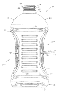
[0011] FIG. 2 is a front
view of an exemplary container incorporating
the features of the present teachings;
[0012] FIG. 3 is a second
side view of an exemplary container
incorporating the features of the present teachings;
[0013] FIG. 4 is a cross-
sectional view of an exemplary container
incorporating the features of the present teachings taken along line 4-4 of
FIG. 3;
[0014] FIG. 5 is a top
cross-sectional view of an exemplary container
incorporating the features of the present teachings taken along line 4-4 of
FIG. 3;
[0015] FIG. 6 is a bottom
perspective, cross-sectional view of an
exemplary container incorporating the features of the present teachings taken
along line 4-4 of FIG. 3; and
[0016] FIG. 7 is an image
illustrate strain concentrations in an
exemplary container incorporating the features of the present teachings.
[0017] Corresponding
reference numerals indicate corresponding parts
throughout the several views of the drawings.
3
CA 02827079 2013-08-09
WO 2012/112513 PCT/US2012/025005
DETAILED DESCRIPTION
[0018] Example
embodiments will now be described more fully with
reference to the accompanying drawings. Example embodiments are provided
so that this disclosure will be thorough, and will fully convey the scope to
those
who are skilled in the art. Numerous specific details are set forth such as
examples of specific components, devices, and methods, to provide a thorough
understanding of embodiments of the present disclosure. It will be apparent to
those skilled in the art that specific details need not be employed, that
example
embodiments may be embodied in many different forms and that neither should
be construed to limit the scope of the disclosure.
[0019] The terminology
used herein is for the purpose of describing
particular example embodiments only and is not intended to be limiting. As
used
herein, the singular forms "a", "an" and "the" may be intended to include the
plural forms as well, unless the context clearly indicates otherwise. The
terms
"comprises," "comprising," "including," and "having," are inclusive and
therefore
specify the presence of stated features, integers, steps, operations,
elements,
and/or components, but do not preclude the presence or addition of one or more
other features, integers, steps, operations, elements, components, and/or
groups
thereof. The method steps, processes, and operations described herein are not
to be construed as necessarily requiring their performance in the particular
order
discussed or illustrated, unless specifically identified as an order of
performance.
It is also to be understood that additional or alternative steps may be
employed.
[0020] When an element or
layer is referred to as being "on", "engaged
to", "connected to" or "coupled to" another element or layer, it may be
directly on,
engaged, connected or coupled to the other element or layer, or intervening
elements or layers may be present. In contrast, when an element is referred to
as being "directly on," "directly engaged to", "directly connected to" or
"directly
coupled to" another element or layer, there may be no intervening elements or
layers present. Other words used to describe the relationship between elements
should be interpreted in a like fashion (e.g., "between" versus "directly
between,"
"adjacent" versus "directly adjacent," etc.). As used herein, the term
"and/or"
includes any and all combinations of one or more of the associated listed
items.
4
CA 02827079 2013-08-09
WO 2012/112513 PCT/US2012/025005
[0021] Although the terms
first, second, third, etc. may be used herein
to describe various elements, components, regions, layers and/or sections,
these elements, components, regions, layers and/or sections should not be
limited by these terms. These terms may be only used to distinguish one
element, component, region, layer or section from another region, layer or
section. Terms such as "first," "second," and other numerical terms when used
herein do not imply a sequence or order unless clearly indicated by the
context.
Thus, a first element, component, region, layer or section discussed below
could
be termed a second element, component, region, layer or section without
departing from the teachings of the example embodiments.
[0022] Spatially relative
terms, such as "inner," "outer," "beneath",
"below", "lower", "above", "upper" and the like, may be used herein for ease
of
description to describe one element or feature's relationship to another
element(s) or feature(s) as illustrated in the figures. Spatially relative
terms may
be intended to encompass different orientations of the device in use or
operation
in addition to the orientation depicted in the figures. For example, if the
device in
the figures is turned over, elements described as "below" or "beneath" other
elements or features would then be oriented "above" the other elements or
features. Thus, the example term "below" can encompass both an orientation of
above and below. The device may be otherwise oriented (rotated 90 degrees or
at other orientations) and the spatially relative descriptors used herein
interpreted accordingly.
[0023] This disclosure
provides for a container being made of PET and
incorporating a vacuum panel design having an optimized size and shape that
resists container contraction caused by hot fill pressure and resultant vacuum
and helps maintain container shape.
[0024] It should be
appreciated that the size and specific configuration
of the container may not be particularly limiting and, thus, the principles of
the
present teachings can be applicable to a wide variety of PET container shapes.
Therefore, it should be recognized that variations can exist in the present
embodiments. That is, it should be appreciated that the teachings of the
present
disclosure can be used in a wide variety of containers, including squeezable
containers, recyclable containers, and the like.
5
CA 02827079 2013-08-09
WO 2012/112513 PCT/US2012/025005
[0025] Accordingly, the
present teachings provide a plastic, e.g.
polyethylene terephthalate (PET), container generally indicated at 10. The
exemplary container 10 can be substantially elongated when viewed from a side
and generally cylindrical when viewed from above and/or rectangular in
throughout or in cross-sections (which will be discussed in greater detail
herein).
Those of ordinary skill in the art would appreciate that the following
teachings of
the present disclosure are applicable to other containers, such as
rectangular,
triangular, pentagonal, hexagonal, octagonal, polygonal, or square shaped
containers, which may have different dimensions and volume capacities. It is
also contemplated that other modifications can be made depending on the
specific application and environmental requirements.
[0026] In some
embodiments, container 10 has been designed to
retain a commodity. The commodity may be in any form such as a solid or semi-
solid product. In one example, a commodity may be introduced into the
container during a thermal process, typically a hot-fill process. For hot-
fill
bottling applications, bottlers generally fill the container 10 with a product
at an
elevated temperature between approximately 155 F to 205 F (approximately
68 C to 96 C) and seal the container 10 with a closure before cooling. In
addition, the plastic container 10 may be suitable for other high-temperature
pasteurization or retort filling processes or other thermal processes as well.
In
another example, the commodity may be introduced into the container under
ambient temperatures.
[0027] As shown in FIGS.
1-3, the exemplary plastic container 10
according to the present teachings defines a body 12, and includes an upper
portion 14 having a cylindrical sidewall 18 forming a finish 20. Integrally
formed
with the finish 20 and extending downward therefrom is a shoulder portion 22.
The shoulder portion 22 merges into and provides a transition between the
finish
20 and a sidewall portion 24. The sidewall portion 24 extends downward from
the shoulder portion 22 to a base portion 28 having a base 30. In some
embodiments, sidewall portion 24 can extend down and nearly abut base 30,
thereby minimizing the overall area of base portion 28 such that there is not
a
discernable base portion 28 when exemplary container 10 is uprightly-placed on
a surface.
6
CA 02827079 2013-08-09
WO 2012/112513 PCT/US2012/025005
[0028] The exemplary
container 10 may also have a neck 23. The
neck 23 may have an extremely short height, that is, becoming a short
extension
from the finish 20, or an elongated height, extending between the finish 20
and
the shoulder portion 22. The upper portion 14 can define an opening for
filling
and dispensing of a commodity stored therein. Although the container is shown
as a beverage container, it should be appreciated that containers having
different shapes, such as sidewalls and openings, can be made according to the
principles of the present teachings.
[0029] The finish 20 of
the exemplary plastic container 10 may include
a threaded region 46 having threads 48, a lower sealing ridge 50, and a
support
ring 51. The threaded region provides a means for attachment of a similarly
threaded closure or cap (not shown). Alternatives may include other suitable
devices that engage the finish 20 of the exemplary plastic container 10, such
as
a press-fit or snap-fit cap for example. Accordingly, the closure or cap
engages
the finish 20 to preferably provide a hermetical seal of the exemplary plastic
container 10. The closure or cap is preferably of a plastic or metal material
conventional to the closure industry and suitable for subsequent thermal
processing.
[0030] In some
embodiments, the container 10 can comprise a
label/vacuum panel area 100 generally disposed along sidewall portion 24. In
some embodiments, panel area 100 can be disposed in other areas of the
container 10, including the base portion 28 and/or shoulder portion 22. Panel
area 100 can comprise a series or plurality of panel sections that generally
resist
fill pressure and maximize vacuum absorption without distorting. Generally,
panel area 100 can be configured and disposed on opposing sides of container
10. In some embodiments, panel areas 100 can be disposed on opposing sides
of a generally rectangular sidewall portion 24 when viewed in cross-section.
[0031] In some
embodiments, each panel area 100 can comprise a
generally oval boundary panel 110. Generally oval boundary panel 110 can
include a plurality of smaller boundary tiles 112 that extend along the outer
edge
of generally oval boundary panel 110 and serve, at least in part, as a
transition
surface from sidewall lands 114 and the surfaces within panel area 100. In
other
words, as seen in FIGS. 1 and 2, boundary tiles 112 can define a generally
7
CA 02827079 2013-08-09
WO 2012/112513 PCT/US2012/025005
curved or arcuate surface extending between and providing a smooth
continuation from sidewall lands 114 to surfaces within panel area 100. It
should
be appreciated that although generally oval boundary panel 110 is described as
having a plurality of boundary tiles 112, each of the plurality of boundary
tiles
112 can be smoothly defined so as to seamlessly transition from one to the
next
to create a generally smooth, flowing, continuous, and uninterrupted boundary
panel 110.
[0032] With continued
reference to FIGS. 1-6, panel area 100 can
further comprise a belt land portion 116 generally extending horizontally
between
opposing boundary tiles 112. Belt land portion 116 can intercept boundary
tiles
112 generally along a transition edge 118, which in some embodiments can
result in a generally converging set of intersecting lines. Belt land portion
116
can be generally flat when view from a side (such as FIG. 1), but also arcuate
or
otherwise curved when viewed from above or in cross section (such as FIGS. 4-
6). This arcuate or otherwise curved shape, when viewed in cross section,
provides increased hoop strength in the container 10 and further provides a
continuous, uninterrupted diameter of container 10 (see FIGS. 4-6). This can
be
particularly useful for application of labels and the like and, moreover,
provides
increased structural rigidity.
Belt land portion 116 can be shaped and/or
configured to further extend along a label area. That is, belt land portion
116 can
be sized and configured to be within the same plane as a later-applied label
and
thus help define a major diameter of container 10.
[0033] An inwardly-
directed rib member 120 can be disposed within
belt land portion 116 and extend horizontally therethrough. Rib member 120 can
comprise a generally straight portion extending toward, but separate from
transition edge 118 such that rib member 120 is completely contained within
belt
land portion 116. Rib member 120 can be sized to include a pair of inwardly
directed surfaces 122 converging at an inner radius 124. Rib member 120 can
be used to reduce and/or otherwise strengthen belt land portion 116 to prevent
or at least minimize expansion under fill pressure.
[0034] Still referring to
FIGS. 1-2, each panel area 100 can further
comprising a pair of inset portions 130 disposed in mirrored relationship
relative
to inwardly-directed rib member 120 and/or belt land portion 116. The pair of
8
CA 02827079 2013-08-09
WO 2012/112513 PCT/US2012/025005
inset portions 130 are configured to each move together with the other in
response to vacuum and/or top loading forces.
Additionally, in some
embodiments, the pair of inset portions 130 can be used as vacuum panels and
as grip panels¨separately or in combination¨as described herein. Still
further,
in some embodiments, the pair of inset portions 130 and belt land portion 116
can together move as a single unit in response to internal vacuum pressure.
[0035] In some
embodiments, inset portions 130 can be configured
and/or shaped as clamshell shaped features 130. Each of the clamshell shaped
features 130 can comprise a plurality of generally circular, C-shaped, or
horseshoe-shaped ribs 132, 134, 136, 138 generally radiating from a central
point 140. Ribs 132, 134, 136, 138 can be outwardly-directed (see FIG. 1) such
that they define inwardly-directed valleys 142, 144, 146 extending between
adjacent ribs 132, 134, 136, 138. A central valley 148 can be disposed within
central rib 132. The outermost rib 138 can transition to generally planar
panel
lands 150, which serve as transitions between each of the pair of clamshell
shaped features and the generally oval boundary panel 110. Each of the pair of
clamshell shaped features 130 provides stiffness to panel area 100 to control
and/or equalize vacuum response over the entire panel area 100 and further
serves to increase panel crystallinity. It should be appreciated, however,
that
alternative configurations of inset portions 130 can be used and are
considered
within the scope of the present disclosure. For example, inset portion 130
could
be rectangular, oval, oblong, etc. Throughout the present disclosure, inset
portion 130 and clamshell shaped features or portion 130 may be used
interchangeably; however, it should be understood that the teachings of the
present disclosure should not be regarded as being limited to the specific
inset
portion configuration described and illustrated herein.
[0036] A final transition
surface 152 can be disposed along ends of
ribs 132, 134, and at least 136 to provide a transition surface between ribs
132,
134, 136 and belt land portion 116.
[0037] With reference to
FIGS. 1-3, in some embodiments, panel area
100 on opposing sides of container 10 can be offset relative to an axial
centerline CL, such that a centerline PL of panel area 100 is not aligned with
centerline CL. In this regard, container 10 can be sized such that a first
side 210
9
CA 02827079 2013-08-09
WO 2012/112513 PCT/US2012/025005
of sidewall portion 24 of container 10 is narrower than an opposing second
side
220. In this regard, sides 210 and/or 220 can be sized to facilitate gripping
by a
user. Moreover, sides 210 and/or 220 can be sized to facilitate gripping by a
user having small hands (side 210) and by a user with large hands (side 220).
Still further, sides 210 and/or 220 can be sized to permit gripping access of
inset
portions 130 by a user to permit inset portions 130 to be used as both vacuum
absorbing features and grip features, simultaneously.
[0038] In some
embodiments, a plurality of parallel, inwardly-directed
ribs 230 can be formed throughout sides 210, 220 of sidewall portion 24. Ribs
230 can be provided to increase rigidity and strength of container 10. Ribs
230
can extend along and be contained by sides 210, 220, thereby not intersecting
panel area 100. Distribution of ribs 230 has further been found to improve the
structural integrity of container 10. Specifically, in some embodiments, it
has
been found that ribs 230 can be disposed parallel and equally spaced along
sidewall portion 24.
[0039] With particular
reference to FIGS. 1-3, container 10 can further
comprise one or more inwardly-directed, circumferential ribs 310. In some
embodiments, circumferential rib 310 can be disposed between or generally
along an interface between shoulder portion 22 and sidewall portion 24,
between
or generally along an interface between base portion 28 and sidewall portion
24,
or both. In some embodiments, circumferential rib 310 can define an arcuate
path about container 10 such that a peak 312 is formed on opposing sides of
container 10. More particularly, in some embodiments, peak 312 can be aligned
with panel area 100 such that peak 312 is generally disposed directly above a
central section of panel area 100 (see FIG. 2). It should be understood that
peak
312 can similarly be a trough 312' formed below and aligned with panel area
100. In some embodiments, as seen in FIGS. 2 and 7, circumferential ribs 310
are formed above and below panel area 100 and serve to direct top loading
forces to away from and around panel area 100, thereby resulting in top
loading
forces being absorbed and carried by sections 314 on opposing sides of panel
area 100.
[0040] Circumferential
ribs 310 can be formed to have an inward
radiused section 316 for improved structural integrity and extending outwardly
CA 02827079 2013-08-09
WO 2012/112513 PCT/US2012/025005
along a corresponding outward radiused section 318 to merge with sidewall
lands 114, which can itself include various features and contours. Through
their
structure, circumferential ribs 310 are capable of resisting the force of
internal
pressure by acting as a "belt" that limits the "unfolding" of the cosmetic
geometry
of the container that makes up the exterior design.
[0041] The plastic
container 10 of the present disclosure is a blow
molded, biaxially oriented container with a unitary construction from a single
or
multi-layer material. A well-known stretch-molding, heat-setting process for
making the one-piece plastic container 10 generally involves the manufacture
of
a preform (not shown) of a polyester material, such as polyethylene
terephthalate (PET), having a shape well known to those skilled in the art
similar
to a test-tube with a generally cylindrical cross section. An exemplary method
of
manufacturing the plastic container 10 will be described in greater detail
later.
[0042] An exemplary
method of forming the container 10 will be
described. A preform version of container 10 includes a support ring 51, which
may be used to carry or orient the preform through and at various stages of
manufacture. For example, the preform may be carried by the support ring, the
support ring may be used to aid in positioning the preform in a mold cavity,
or the
support ring may be used to carry an intermediate container once molded. At
the outset, the preform may be placed into the mold cavity such that the
support
ring is captured at an upper end of the mold cavity. In general, the mold
cavity
has an interior surface corresponding to a desired outer profile of the blown
container. More specifically, the mold cavity according to the present
teachings
defines a body forming region, an optional moil forming region and an optional
opening forming region. Once the resultant structure, hereinafter referred to
as
an intermediate container, has been formed, any moil created by the moil
forming region may be severed and discarded. It should be appreciated that the
use of a moil forming region and/or opening forming region are not necessarily
in
all forming methods.
[0043] In one example, a
machine (not illustrated) places the preform
heated to a temperature between approximately 190 F to 250 F (approximately
88 C to 121 C) into the mold cavity. The mold cavity may be heated to a
temperature between approximately 250 F to 350 F (approximately 121 C to
11
CA 02827079 2013-08-09
WO 2012/112513 PCT/US2012/025005
177 C). A stretch rod apparatus (not illustrated) stretches or extends the
heated
preform within the mold cavity to a length approximately that of the
intermediate
container thereby molecularly orienting the polyester material in an axial
direction generally corresponding with the central longitudinal axis of the
container 10. While the stretch rod extends the preform, air having a pressure
between 300 PSI to 600 PSI (2.07 MPa to 4.14 MPa) assists in extending the
preform in the axial direction and in expanding the preform in a
circumferential or
hoop direction thereby substantially conforming the polyester material to the
shape of the mold cavity and further molecularly orienting the polyester
material
in a direction generally perpendicular to the axial direction, thus
establishing the
biaxial molecular orientation of the polyester material in most of the
intermediate
container. The pressurized air holds the mostly biaxial molecularly oriented
polyester material against the mold cavity for a period of approximately two
(2) to
five (5) seconds before removal of the intermediate container from the mold
cavity. This process is known as heat setting and results in a heat-resistant
container suitable for filling with a product at high temperatures.
[0044] Alternatively, other manufacturing methods, such as for
example, extrusion blow molding, one step injection stretch blow molding and
injection blow molding, using other conventional materials including, for
example,
high density polyethylene, polypropylene, polyethylene naphthalate (PEN), a
PET/PEN blend or copolymer, and various multilayer structures may be suitable
for the manufacture of plastic container 10. Those having ordinary skill in
the art
will readily know and understand plastic container manufacturing method
alternatives.
[0045] The foregoing
description of the embodiments has been
provided for purposes of illustration and description. It is not intended to
be
exhaustive or to limit the invention.
Individual elements or features of a
particular embodiment are generally not limited to that particular embodiment,
but, where applicable, are interchangeable and can be used in a selected
embodiment, even if not specifically shown or described. The same may also be
varied in many ways. Such variations are not to be regarded as a departure
from
the invention, and all such modifications are intended to be included within
the
scope of the invention.
12