Note: Descriptions are shown in the official language in which they were submitted.
CA 02827086 2013-08-09
WO 2013/022498 PCT/US2012/032806
REDUCED-PRESSURE DRESSINGS, SYSTEMS, AND METHODS WITH
EVAPORATIVE DEVICES
RELATED APPLICATIONS
[0001] The present invention relates generally to methods, systems and
compositions
for The present invention claims the benefit, under 35 USC 119(e), of the
following filings
of U.S. Provisional Patent Application Serial Number 61/529,722, entitled
"REDUCED-
PRESSURE DRESSINGS, SYSTEMS, AND METHODS WITH EVAPORATIVE
DEVICES," filed on 31 August 2011, which is incorporated herein by reference
for all
purposes; U.S. Provisional Patent Application Serial Number 61/529,709,
entitled
"EVAPORATIVE FLUID POUCH AND SYSTEMS FOR USE WITH BODY FLUIDS,"
filed 31 August 2011, which is incorporated herein by reference for all
purposes; U.S.
Provisional Patent Application Serial Number 61/529,735, entitled "ABSORBENT
POLYMER DRESSINGS, SYSTEMS, AND METHODS EMPLOYING EVAPORATIVE
DEVICES," filed 31 August 2011, which is incorporated herein by reference for
all purposes;
U.S. Provisional Patent Application Serial Number 61/529,751, entitled
"REDUCED-
PRESSURE INTERFACES, SYSTEMS, AND METHODS EMPLOYING A COANDA
DEVICE," filed on 31 August 2011, which is incorporated herein by reference
for all
purposes; and U.S. Patent Application Serial No. 13/084,813, entitled
"DRESSINGS AND
METHODS FOR TREATING A TISSUE SITE ON A PATIENT," filed on 12 April 2011,
which is incorporated herein by reference for all purposes.
TECHNICAL FIELD
[0002] The present disclosure relates generally to medical treatment systems
for
treating wounds that produce liquids, such as exudate, and more particularly,
but not by way
of limitation, to reduced-pressure medical dressings, systems, and methods
with evaporative
devices.
BACKGROUND
[0003] Caring for wounds is important in the healing process. Wounds often
produce
considerable liquids, e.g., exudate. Medical dressings are often used in wound
care to address
the production of liquids from the wound. If not properly addressed, liquids
at the wound can
1
CA 02827086 2013-08-09
WO 2013/022498 PCT/US2012/032806
lead to infection or maceration of the periwound area. As used throughout this
document, "or"
does not require mutual exclusivity. Wound dressings may be used alone or as
an aspect of
applying reduced pressure to a tissue site.
[0004] Clinical studies and practice have shown that providing a reduced
pressure in
proximity to a tissue site augments and accelerates the growth of new tissue
at the tissue site.
The applications of this phenomenon are numerous, but application of reduced
pressure has
been particularly successful in treating wounds. This treatment (frequently
referred to in the
medical community as "negative pressure wound therapy," "reduced pressure
therapy," or
"vacuum therapy") provides a number of benefits, which may include faster
healing and
increased formulation of granulation tissue.
2
CA 02827086 2013-08-09
WO 2013/022498
PCT/US2012/032806
SUMMARY
[0005] According to an illustrative embodiment, a wound treatment system for
treating
a wound on a patient includes a treatment manifold for disposing proximate to
the wound.
The treatment manifold has a first side and a second, patient-facing side. The
wound
treatment system further includes a first sealing member for disposing over
the first side of the
treatment manifold to create a sealed space containing the treatment manifold.
The first
sealing member comprises a high-moisture-vapor-transfer-rate drape. The wound
treatment
system also includes an air-movement manifold having a first side and a
second, patient-facing
side. The second, patient-facing side is disposed proximate to the first side
of the first sealing
member. The wound treatment system further includes a second sealing member
disposed
over the first side of the air-movement manifold forming a channel space, at
least one port
formed on the second sealing member for allowing air to exit the channel
space, and a
reduced-pressure source for producing reduced pressure. The reduced-pressure
source is
fluidly coupled to the sealed space for delivering reduced pressure thereto.
The wound
treatment system also includes a pressure source and a Coanda device. The
Coanda device is
coupled to the second sealing member and fluidly coupled to the pressure
source and to the
channel space. The Coanda device includes an annular nozzle forming a central
opening and
having an interior passage and a nozzle opening, and a Coanda surface
proximate to and
downstream from the nozzle opening, whereby fluid exiting the nozzle opening
entrains
additional fluid from the central opening and produces a combined fluid flow.
The Coanda
device is fluidly coupled to a Coanda opening in the second sealing member.
[0006] According to another illustrative embodiment, a wound treatment
dressing for
treating a wound on a patient includes a treatment manifold for disposing on
the wound. The
treatment manifold has a first side and a second, patient-facing side. The
wound treatment
dressing also includes a first sealing member for disposing over the first
side of the treatment
manifold to create a sealed space containing the treatment manifold. The first
sealing member
comprises a high-moisture-vapor-transfer-rate drape. The wound treatment
dressing further
includes an air-movement manifold having a first side and a second, patient-
facing side. The
second, patient-facing side is disposed proximate to the first side of the
first sealing member.
The wound treatment dressing also includes a second sealing member disposed
over the first
= side of the air-movement manifold to form a channel space, at least one
port formed on the
second sealing member to allow air to exit the channel space, and a Coanda
device coupled to
3
CA 02827086 2013-08-09
WO 2013/022498
PCT/US2012/032806
the second sealing member. The Coanda device includes an annular nozzle
forming a central
opening and having an interior passage and a nozzle opening, and a Coanda
surface position
proximate to and downstream from the nozzle opening, whereby fluid exiting the
nozzle
opening entrains additional fluid from the central opening and produces a
combined fluid
flow. The Coanda device is fluidly coupled to a Coanda opening in the second
sealing
member.
[0007] According to another illustrative embodiment, a wound dressing for
treating a
wound on a patient includes a means for receiving and retaining liquids from
the wound; a
means for moving liquid away from the means for receiving and retaining
liquids; and a means
for evaporating liquid from the means for moving liquid. The means for
evaporating a liquid
may be a Coanda device.
[0008] According to another illustrative embodiment, a method for treating a
wound
on a patient comprises disposing a treatment manifold proximate to the wound.
The treatment
manifold has a first side and a second, patient-facing side. The method
further includes
covering the treatment manifold an a portion of intact skin with a first
sealing member to
create a sealed space containing the treatment manifold. The first sealing
member comprises a
high-moisture-vapor-transfer-rate drape and has at least one port. The method
also involves
disposing an air-movement manifold proximate to the first sealing member,
disposing a
second sealing member over the air-movement manifold to form a channel space,
fluidly
coupling a reduced-pressure source to the sealed space for delivering reduced
pressure thereto,
and coupling a Coanda device to the second sealing member. The method further
includes
fluidly coupling the Coanda device to a pressure source and to the channel
space. The
Coanda device includes an annular nozzle forming a central opening and having
an interior
passage and a nozzle opening, and a Coanda surface proximate to and downstream
from the
nozzle opening, whereby fluid exiting the nozzle opening entrains additional
fluid from the
central opening and produces a combined fluid flow. The method further
includes fluidly
coupling the Coanda device to a Coanda opening in the second sealing member
and providing
positive pressure to the Coanda device to cause fluid flow within the air-
movement manifold.
[0009] According to another illustrative embodiment, a wound treatment system
for
treating a wound on a patient includes a treatment manifold for disposing on
the wound. The
treatment manifold has a first side and a second, patient-facing side. The
wound treatment
system further includes a first sealing member for disposing over the first
side of the treatment
manifold to create a sealed space containing the treatment manifold. The first
sealing member
4
CA 02827086 2013-08-09
WO 2013/022498
PCT/US2012/032806
comprises a high-moisture-vapor-transfer-rate drape and an air-movement
manifold having a
first side and a second, patient-facing side. The second, patient-facing side
of the air-
movement manifold is disposed proximate to the first side of the first sealing
member. The
wound treatment system includes a second sealing member disposed over the
first side of the
air-movement manifold to form a channel space and at least one exhaust port
formed on the
second sealing member for allowing air to exit the channel space. The system
further includes
a first pump for producing reduced pressure. The first pump is fluidly coupled
to the sealed
space for delivering reduced pressure thereto. The wound treatment system also
includes a
second pump for producing a positive pressure. The second pump is fluidly
coupled to the
channel space; and wherein the first pump and second pump are at least 5
centimeters from the
first sealing member.
[0010] According to another illustrative embodiment, a wound treatment system
for
treating a wound on a patient includes a treatment manifold for disposing on
the wound,
wherein the treatment manifold has a first side and a second, patient-facing
side; a first sealing
member for disposing over the first side of the treatment manifold and a
portion of intact skin
to create a sealed space containing the treatment manifold, wherein the first
sealing member
comprises a high-moisture-vapor-transfer-rate drape; an air-movement manifold
having a first
side and a second, patient-facing side, wherein the second, patient-facing
side is disposed
proximate to the first side of the first sealing member; a second sealing
member disposed over
the first side of the air-movement manifold forming a channel space; and at
least one exhaust
port formed on the second sealing member for allowing air to exit the channel
space. The
system further includes a pump for producing reduced pressure, wherein the
pump is fluidly
coupled to the sealed space for delivering reduced pressure thereto and
fluidly coupled to the
channel space for delivering reduced pressure thereto.
[0011] According to another illustrative embodiment, a wound treatment system
for
treating a wound on a patient includes a treatment manifold for disposing on
the wound,
wherein the treatment manifold has a first side and a second, patient-facing
side; a first sealing
member for disposing over the first side of the treatment manifold and a
portion of intact skin
to create a sealed space containing the treatment manifold, wherein the first
sealing member
comprises a high-moisture-vapor-transfer-rate drape; an air-movement manifold
having a first
side and a second, patient-facing side, wherein the second, patient-facing
side is disposed
proximate to the first side of the first sealing member; a second sealing
member disposed over
the first side of the air-movement manifold forming a channel space; and at
least one exhaust
5
CA 02827086 2013-08-09
WO 2013/022498
PCT/US2012/032806
port formed on the second sealing member for allowing air to exit the channel
space. The
system further includes a first interface fluidly coupled to the sealed space;
a second interface
fluidly coupled to the channel space; a first reduced-pressure conduit fluidly
coupled to the
first interface; a second-reduced pressure conduit fluidly coupled to the
second interface; and a
pump for producing reduced pressure. The pump is fluidly coupled to the first
reduced-
pressure conduit and to the second reduced-pressure conduit to deliver reduced
pressure to the
first reduced-pressure conduit and to the second reduced-pressure conduit.
[0012] According to another illustrative embodiment, a wound treatment system
for
treating a wound on a patient includes a treatment manifold for disposing on
the wound,
wherein the treatment manifold has a first side and a second, patient-facing
side; a first sealing
member for disposing over the first side of the treatment manifold and a
portion of intact skin
to create a sealed space containing the treatment manifold, wherein the first
sealing member
comprises a high-moisture-vapor-transfer-rate drape; an air-movement manifold
having a first
side and a second, patient-facing side, wherein the second, patient-facing
side is disposed
proximate to the first side of the first sealing member; and a second sealing
member disposed
over the first side of the air-movement manifold forming a channel space. The
system further
includes at least one exhaust port formed on the second sealing member for
allowing air to exit
the channel space; a plurality of bellows extending from the second sealing
member through at
least the first sealing member; a first reduced-pressure source fluidly
coupled to the sealed
space; and a second reduced-pressure source fluidly coupled to the plurality
bellows and
operable to cause the bellows to move from a first, free state to a second,
collapsed state under
reduced pressure, whereby at least some air in the air-movement manifold is
forced out the at
least one exhaust port.
[0013] Other aspects, features, and advantages of the illustrative embodiments
will
become apparent with reference to the drawings and detailed description that
follow.
6
CA 02827086 2013-08-09
WO 2013/022498
PCT/US2012/032806
BRIEF DESCRIPTION OF THE DRAWINGS
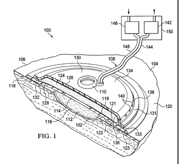
[0014] FIGURE 1 is a schematic, perspective view, with a portion shown in
cross
section, of an illustrative embodiment of a wound treatment system for
treating a wound on a
patient;
[0015] FIGURE 2 is a schematic, perspective view of an illustrative embodiment
of a
Coanda device;
[0016] FIGURE 3 is a schematic cross section of the Coanda device of FIGURE 2;
[0017] FIGURE 4 is a schematic diagram of a wound treatment system for
treating a
wound on a patient;
[0018] FIGURE 5 is a schematic diagram, with a portion shown in cross section,
of an
illustrative embodiment of a wound treatment system for treating a wound on a
patient;
[0019] FIGURE 6 is a schematic diagram, with a portion shown in cross section,
of an
illustrative embodiment of a wound treatment system for treating a wound on a
patient;
[0020] FIGURE 7 is a schematic diagram, with a portion shown in cross section,
of an
illustrative embodiment of a wound treatment system for treating a wound on a
patient;
[0021] FIGURE 8 is a schematic cross section of an illustrative embodiment of
a
pressure conduit;
[0022] FIGURE 9 is a schematic cross section of an illustrative embodiment of
a
pressure conduit;
[0023] FIGURE 10A is a schematic diagram, with a portion shown in cross
section, of
an illustrative embodiment of a wound treatment system for treating a wound on
a patient
shown in an extended position; and
[0024] FIGURE 10B is a schematic diagram, with a portion shown in cross
section, of
the illustrative embodiment of a wound treatment system of FIGURE 10A shown in
a collapse
state.
7
CA 02827086 2013-08-09
WO 2013/022498
PCT/US2012/032806
DETAILED DESCRIPTION OF ILLUSTRATIVE EMBODIMENTS
[0025] In the following detailed description of the illustrative, non-limiting
embodiments, reference is made to the accompanying drawings that form a part
hereof. These
embodiments are described in sufficient detail to enable those skilled in the
art to practice the
invention, and it is understood that other embodiments may be utilized and
that logical
structural, mechanical, electrical, and chemical changes may be made without
departing from
the spirit or scope of the invention. To avoid detail not necessary to enable
those skilled in the
art to practice the embodiments described herein, the description may omit
certain information
known to those skilled in the art. The following detailed description is not
to be taken in a
limiting sense, and the scope of the illustrative embodiments are defined only
by the appended
claims.
[0026] Referring now to the drawings and initially to FIGURE 1, an
illustrative
embodiment of a wound treatment system 100 for treating a wound 102 on a
patient 104 is
presented. The wound 102 may any damaged or irregular tissue. The wound 102 is
shown
extending partially through epidermis 106. The wound treatment system 100 is
particularly
well suited for wounds that produce liquids. An evaporative subsystem 108
helps remove
fluids from the system 100. In this embodiment, the evaporative subsystem 108
includes a
Coanda device 110 as will be described further below.
[0027] The wound treatment system 100 includes a treatment manifold 112 for
disposing proximate to the wound. The treatment manifold 112 has a first side
114 and a
second, patient-facing side 116. The treatment manifold 112 is for
distributing reduced
pressure to and receiving fluids, including liquids, from the wound 102, and
may be any
material that functionally carries out these tasks. Manifold generally refers
to a substance or
structure that is provided to assist in applying reduced pressure to,
delivering fluids to, or
removing fluids from a tissue site or wound. Examples of treatment manifolds
112 may
include, without limitation, one or more of the following: devices that have
structural
elements arranged to form flow channels, such as, for example, cellular foam,
open-cell foam,
porous tissue collections, liquids, gels, and foams that include, or cure to
include, flow
channels; porous material porous, such as foam, gauze, felted mat, or any
other material suited
to a particular biological application; or porous foam that includes a
plurality of interconnected
cells or pores that act as flow channels, e.g., a polyurethane, open-cell,
reticulated foam such
as GranuFoami material manufactured by Kinetic Concepts, Incorporated of San
Antonio,
8
CA 02827086 2013-08-09
WO 2013/022498
PCT/US2012/032806
Texas; a bioresorbable material; or a scaffold material.
[0028] The treatment manifold 112 is covered by a first sealing member 118.
The first
sealing member 118 is disposed over the first side 114 of the treatment
manifold 112 and a
portion of intact skin 120 to create a sealed space 122 containing the
treatment manifold 112.
The first sealing member 118 may be adhered to the intact skin 120 by an
attachment device
123, e.g., an adhesive, and to the first side 114 of the treatment manifold
112. The first sealing
member 118 comprises a high-moisture-vapor-transfer-rate drape. "Moisture
Vapor
Transmission Rate" or "MVTR" represents the amount of moisture that can pass
through a
material in a given period of time. A first high-moisture-vapor-transfer-rate
drape typically
has a moisture vapor transmission rate greater than 300g/m2/24 hours and more
typically
1000g/m2/24 hours or more. The first sealing member 118 allows vapor to egress
from the
treatment manifold 112 through first sealing member 118 and into an air-
movement manifold
124. The first sealing member 118 has a first side 119 and a second, patient-
facing side 121.
[0029] The first sealing member 118 may comprise any of numerous materials,
such as
any of the following: hydrophilic polyurethanes, cellulosics, hydrophilic
polyamides,
polyvinyl alcohol, polyvinyl pynolidone, hydrophilic silicone polymers,
hydrophilic acrylics,
hydrophilic silicone elastomers and copolymers of these. As one specific,
illustrative, non-
limiting embodiment, the first sealing member 118 may be formed from a
breathable cast mat
polyurethane film sold under the name INSPIRE 2301 from Expopack Advanced
Coatings of
Wrexham, United Kingdom. That illustrative sealing member has a MVTR (inverted
cup
technique) of 14500 - 14600 g/m2/24 hours. See
www.exopackadvancedcoatings.com. The
first sealing member 118 may have various thicknesses, such as 10 to 40
microns (gm), e.g.,
15, 20, 25, 30, 35, 40 microns or any number in the stated range.
[0030] As previously noted, the first sealing member 118 may be adhered to the
intact
skin 120 by an attachment device 123, e.g., an adhesive, and to the first side
114 of the
treatment manifold 112. The performance of the first sealing member 118 with
respect to
MVTR may be enhanced by only covering a limited surface area of the second,
patient-facing
side 121 of the first sealing member 112 with the attachment device 123. For
example, only
the peripheral edge of the first sealing member 118 may be covered or a
limited pattern may
be used. In the latter situation, according to one illustrative embodiment,
only 30 to 60
percent of the surface area is covered with the attachment device 123. The
limited coverage
by the attachment device 123 on the second, patient-facing side 121 may be
accomplished by
applying the attachment device 123 in a pattern, e.g., grid, spaced dots,
swirls, or other
9
CA 02827086 2013-08-09
WO 2013/022498
PCT/US2012/032806
patterns. In another embodiment, the first sealing member 118 may be coupled
by welding
(e.g., ultrasonic or RF welding), bonding, stitching, staples, or another
coupling device to the
first side 114 of the treatment manifold 112. The attachment device 123 may be
applied only
to a peripheral portion of the first sealing member 118.
[0031] The air-movement manifold 124 has a first side 126 and a second,
patient-
facing side 128. The second, patient-facing side 128 is disposed proximate to
the first side
119 of the first sealing member 118. The air-movement manifold 124 provides
open pathways
for airflow even when under compression developed by the system 100. The air-
movement
manifold 124 may be any substance that carries out these functions. The air-
movement
manifold 124 may be, for example, one or more of the following: open cell
foam, woven or
non-woven material, porous polymer, molded matrix, or sintered polymers.
[0032] A second sealing member 130 disposed over or covers the first side of
the air-
movement manifold 124 forming a channel space 132. The second sealing member
130 has a
first side 134 and a second, patient-facing side 136. The second, patient-
facing side 136 of the
second sealing member 130 is disposed against the first side 126 of the air-
movement
manifold 124. The second sealing member 130 may have an extension portion 131
that is
attached by an attachment device 133 to a portion of the first sealing member
118 or otherwise
sealed. The second sealing member 130 may be formed from one or more of the
following
materials: all those mentioned for the first sealing member 118, as well as
low MVTR films.
Woven and non-woven materials may also be used as long as the materials are
constructed or
coated such that the materials adequately contain and control the air flow.
[0033] The second sealing member 130 helps direct airflow in the channel space
132
and may allow egress of vapors. At least one port 138 is formed on the second
sealing
member 130 for allowing air to exit the channel space 132. More typically, a
plurality of ports
140 are formed through the second sealing member 130 and are typically spaced
from the
Coanda device 110 or other air mover. A bacterial filter (not shown) may cover
each of the
plurality of ports 140 as a safeguard against bacteria entering the wound 102
if a breach is
created in the first sealing member 118. As with the first sealing member 118,
the second
sealing member 130 may have limited coverage on the second, patient-facing
side 136 of the
attachment device 133.
[0034] The wound treatment system 100 includes a reduced-pressure source 142
for
producing reduced pressure. The reduced-pressure source 142 is fluidly coupled
to the sealed
space 122 for delivering reduced pressure to the sealed space 122. The reduced
pressure is
CA 02827086 2013-08-09
WO 2013/022498
PCT/US2012/032806
used to treat the tissue at the wound 102 and to remove fluids, including
liquids, from the
wound 102. The reduced-pressure source 142 may be a vacuum pump, wall suction,
micro-
pump, or other source.
[0035] The reduced-pressure source 142 is fluidly coupled to the sealed space
122 by a
reduced-pressure conduit 144. The reduced-pressure conduit 144 is shown
associated with the
Coanda device 110. Yet it should be understood that the reduced-pressure
conduit 144 may
separately extend through the second sealing member 130, air-movement manifold
124, first
sealing member 118 and into the treatment manifold 112 or may be fluidly
coupled using a
reduced-pressure interface (e.g., a Sensi-TRAC interface available from KCI,
Inc. of San
Antonio, Texas); or any other means.
[0036] The wound treatment system 100 further includes a pressure source 146,
which
is a positive-pressure source, that is fluidly coupled to the Coanda device
110. The pressure
source 146 may be any source of positive pressure including, without
limitation, a pump, a
wall source, a pressurize canister, or other means. A diaphragm pump is well
suited in many
applications. The pressure source 146 is fluidly coupled to the Coanda device
110 by a
conduit 148. The pressure source 146 may be housed with the reduced-pressure
source 142 in
a pressure unit 150.
[0037] The Coanda device 110 is a device for entraining air for desired
purpose using
the Coanda effect. The Coanda effect is generally phenomena in which a flow
attaches itself
to a nearby surface and remains attached even as the surface (Coanda surface)
pulls away from
the flows initial direction. As the flow curves away, it will entrain
surrounding fluids and
increasing the volume of the flow. Without being limited to theory, it appears
that the surface
that is brought close to the flow restricts the entrainment in that region and
as the flow
accelerates to try to balance the momentum transfer, a pressure differential
develops across the
flow and the direction is changed or deflected closer to the surface. The
effect is named for
Henri Coanda and the concept is described in United States Patent 2,052,869,
granted to
Coanda.
[0038] Thus, in the illustrative embodiment of FIGURE 1, the Coanda device 110
creates a desired airflow. The Coanda device 110 is coupled to the second
sealing member
130 and fluidly coupled to the pressure source 146 and to the channel space
132. The Coanda
device 110 receives positive pressure air from the conduit 148 and develops an
enhanced flow
that is delivered from the Coanda device 110 into the air-movement manifold
124 and more
11
CA 02827086 2013-08-09
WO 2013/022498
PCT/US2012/032806
generally into the channel space 132. The airflow flows through the channel
space 132 and
air-movement manifold 124 and exits the one or more ports 138, 140.
[0039] As the air moves through the channel space 132 and air-movement
manifold
124, any moisture or vapor on the first side 119 of the first sealing member
118. This in turn
will increase or maintain a humidity gradient across the first sealing member
118 that helps
remove liquid from the treatment manifold 112. That in turn provides many
benefits including
an increased ability to process liquids. It should be noted that other
entrainment devices may
be used as the Coanda device 110 or to entrain air into the dressing to
achieve the desired air-
flow. These other devices may be used to entrain air to create a more
voluminous flow due to
the presence of a high pressure flow, such as a Conventional Ejector, where a
primary flow is
located proximate to an available secondary air source that is "dragged" by an
aerofoil shape
to have the effect of an air-multiplier.
[0040] Referring now primarily to FIGURES 2-3, an illustrative Coanda device
110 is
presented. The Coanda device 110 includes an annular nozzle 152. The annular
nozzle 152
forms a central opening 154. The annular nozzle 152 has walls 156 that form an
interior
passage 158. A nozzle opening 160 is formed on the annular nozzle 152 towards
the central
opening 154. A portion of the walls 156 forms a Coanda surface 162 proximate
to and
downstream from the nozzle opening 160. The fluid or air exiting the nozzle
opening 160
entrains additional fluid from the central opening 154 as the flow follows the
Coanda surface
162. The flow of air plus the entrained air produce a combined fluid flow. The
Coanda device
110 is fluidly coupled to a Coanda opening 164 or aperture in the second
sealing member 130
that allows the flow into the channel space 132 and air-movement manifold 124.
[0041] For the configuration shown, air is moved out of the nozzle opening 160
as
suggested by arrows 166 in FIGURE 3. The airflow entrains additional air from
the central
opening 154 as suggested by arrows 168. The combined fluid flow is suggested
by arrows
170. It should be apparent that if a volume V1 of air is delivered by conduit
148 to the Coanda
device 110 over a time T and a volume V2 of air is delivered through the
central opening 154
of the Coanda device over time T, the combined air flow (V2+ V1) will be
enhanced. It
should be understood that the Coanda device 110 may be flipped as well such
that the nozzle
opening 160 discharges air away from the second sealing member 130 and air
that is recruited
from the central opening 154 is pulled from the Coanda opening 164 in the
second sealing
member 130. In this latter embodiment, the Coanda device 110 is configured to
pull fluid
from the Coanda opening 164 thereby pulling fluid from the at least one port
138 through the
12
CA 02827086 2013-08-09
WO 2013/022498
PCT/US2012/032806
air-movement manifold 124 and out the Coanda opening 164. A high pressure flow
is
delivered to the Coanda device 110 and a low pressure flow is created with the
combined fluid
flow.
[0042] Referring now to FIGURE 4, a diagram of the wound treatment system 100
is
presented that demonstrates active control of the system 100. The wound
treatment system
100 of FIGURE 4 is analogous to FIGURE 1, except a controller 172 and a
saturation sensor
174 have been added. The saturation sensor 174 is operatively coupled to the
treatment
manifold 112 and to the controller 172. The controller includes a battery (not
explicitly
shown). The controller 172 and saturation sensor 174 determine when the
treatment manifold
112 is saturated. Saturated means that the amount of liquid in the treatment
manifold 112 has
exceeded a first threshold or design threshold. The controller may then
activate the pressure
source 146 causing airflow in the air-movement manifold 124 to help remove
liquids.
Likewise, when the controller 172 and saturation sensor 174 determine that the
treatment
manifold 112 is no longer saturated, the controller 172 may deactivate the
pressure source 146.
[0043] The saturation sensor 174 may be any device that allows monitoring of
the
saturation status of the treatment manifold 112. For example, without
limitation, the
saturation sensor 174 may be a resistive element that changes resistance when
liquid covers
the resistive elements, a galvanic cell that creates a voltage when covered
with liquid from a
wound, or a capacitive sensor that changes properties when saturated liquid is
nearby, or any
other electrical saturation sensor.
[0044] Referring generally to FIGURES 1-4, according to one illustrative
embodiment,
the treatment manifold 112 is disposed proximate to the wound 102. The
treatment manifold
112 and a portion of intact skin 120 are covered with the first sealing member
118 to create the
sealed space 122 containing the treatment manifold 112. The air-movement
manifold 124 is
disposed proximate to the first sealing member 118. The second sealing member
130 is
disposed over the air-movement manifold 124 to form the channel space 132. The
reduced-
pressure source 142 is fluidly coupled to the sealed space 122 for delivering
reduced pressure
thereto.
[0045] The Coanda device 110 is coupled to the second sealing member 130. The
Coanda device 110 is fluidly coupled to the pressure source 146 and to the
channel space 132.
The Coanda device 110 is fluidly coupled to the Coanda opening 164 in the
second sealing
member 130. Positive pressure is then provided from the pressure source 146 to
the Coanda
device 110 to cause fluid flow within the air-movement manifold 124. The
positive pressure
13
CA 02827086 2013-08-09
WO 2013/022498
PCT/US2012/032806
may be continuously or intermittently provided to the Coanda device 110. The
intermittent
cycle may be fixed or variable based on a number of factors such as
anticipated saturation,
actual saturation, stage of therapy, remaining battery capacity, or other
factors. The positive
pressure may also be actively controlled using a controller 172 and saturation
sensor 174 as
discussed in connection with FIGURE 4.
[0046] The evaporative subsystem 108 includes the air-movement manifold 124,
second sealing member 130, and a source of air movement in the air-movement
manifold 124,
e.g., the Coanda device 110. Other sources of air movement may be used as part
of the
evaporative subsystem 108.
[0047] Referring now to FIGURE 5, another wound treatment system 100 for
treating
a wound 102 on a patient 104 is presented. The wound treatment system 100 is
analogous in
many respects to the wound treatment system 100 of FIGURE 1, and accordingly,
some parts
are labeled but not further discussed. The wound 102 extends through epidermis
106 and
dermis 107. In this embodiment, the Coanda device 110 is replaced by
delivering positive
pressure directly to the channel space 132 and air-movement manifold 124.
[0048] The reduced-pressure source 142 may be, for example, a first pump or
vacuum
pump or any other source as previously mentioned for producing reduced
pressure. As before,
the reduced-pressure source 142 is fluidly coupled to the sealed space 122 for
delivering
reduced pressure thereto. A reduced-pressure conduit 144 fluidly couples the
reduced-
pressure source 142 to a first pressure interface 176. The first pressure
interface 176 is fluidly
coupled to the sealed space 122.
[0049] The pressure source 146 may be a second pump or any other source as
previously mentioned. The pressure source 146 is fluidly coupled by a conduit
148 to a
second pressure interface 178. The second pressure interface 178 is fluidly
coupled to the
channel space 132. It should be appreciated that the pressure source 146 may
supply positive
pressure or may pull air from the second pressure interface 178. In either
case, air flow will be
produced in the channel space 132.
[0050] As with all the embodiments herein, the active control components of
FIGURE
4 may be readily added to this embodiment as well. The pressure source 146 and
reduced-
pressure source 142 are remote, e.g., at least 5 centimeters and typically
more than 14
centimeters from the first pressure interface 176 and second pressure
interface 178
respectively.
[0051] Referring now primarily to FIGURE 6, another wound treatment system 100
14
CA 02827086 2013-08-09
WO 2013/022498
PCT/US2012/032806
for treating a wound 102 on a patient 104 is presented. The wound treatment
system 100 is
analogous in many respects to the wound treatment system 100 of FIGURES 1 and
5, and
accordingly, some parts are labeled in FIGURE 6 but are not further discussed.
In the
illustrative embodiment of FIGURE 6, a pump 180 is used for the reduced-
pressure source 142
and as the pressure source 146. The first pressure interface 176 is fluidly
coupled to the
sealed space 122, and the second interface 178 is fluidly coupled to the
channel space 132.
The first conduit 144 is fluidly coupled to the first pressure interface 176.
The second conduit
148 is fluidly coupled to the second interface 178. The pump 180 is operable
to produce
reduced pressure and a positive-pressure exhaust. The pump 180 is fluidly
coupled to the first
conduit 144 and to the second conduit 148. A bacteria filter 182 is associated
with the second
conduit 148 for removing bacteria from the air flow therein. The air is thus
filtered before
entering the channel space 132.
[0052] A valve 184 may be on a tributary conduit 186 that is fluidly coupled
to the low
pressure side of the pump 180. The valve 184 allows air to enter the pump 180
from an inlet
188 once the set reduced pressure is realized in the valve 184. This flow
allows the pump 180
to produce exhaust that is delivered to conduit 148. The valve 184 may be a
proportional
valve or any other type of valve, and typically is selected or adjusted to
allow flow to enter the
pump 180 when the pressure realized in the conduit 144 is -125 mm Hg or more
negative (e.g.,
-125 to -200 mm Hg).
[0053] Referring now to FIGURE 7, another wound treatment system 100 for
treating
a wound 102 on a patient 104 is presented. The wound treatment system 100 is
analogous in
many respects to the wound treatment system 100 of FIGURES 1 and 5, and
accordingly,
some parts are labeled in FIGURE 7 but are not further discussed. In the
illustrative
embodiment of FIGURE 7, a single pump 180 is again used, but this time the low
pressure
side of the pump 180 is used for the evaporative subsystem 108 and the reduced-
pressure
treatment at the wound 102.
10054] The low pressure side (suction side) 181 of the pump 180 is fluidly
coupled to
both the first conduit 144 and second conduit 148. Thus, in this embodiment,
air is pulled into
the at least one port 138 or plurality of ports, through the air-movement
manifold 124, and
through second conduit 148 to the pump 180. The pump 180 is sized to have
sufficient
capacity to simultaneously maintain the desired reduced pressure at the wound
102 and
provide sufficient flow through the evaporative subsystem 108. A valve 190 is
in line with the
second conduit 148 and remains closed until the pressure in the first conduit
144 reaches a
CA 02827086 2013-08-09
WO 2013/022498
PCT/US2012/032806
threshold reduced pressure. When the threshold reduced pressure is reached,
the valve opens
and allows flow in the second conduit 148. The valve may be a proportional
valve, needle
valve, gate valve, or other valve type.
100551 Referring now primarily to FIGURE 8, a pressure conduit 192 for use
with a
wound treatment system is presented. The pressure conduit 192 includes a
conduit body 194
having an aspect ratio in lateral cross section greater than two. Aspect ratio
is the longer
dimension 193 over the shorter dimension 195. The pressure conduit 192 has two
peripheral
conduits 196, 198 and two void passages 200, 202 separated by a support wall
205.
[0056] Referring now primarily to FIGURE 9, another illustrative embodiment of
a
pressure conduit 192 for use with a wound treatment system, such as wound
treatment system
100 in FIGURE 1, is presented. The pressure conduit 192 includes a pouch 204
having an
interior space 206, a gas-transport material 208 disposed within the interior
space 206, and at
least one internal conduit 210 disposed within the interior space 206. The
pouch 204 may be
formed by two polymer sheets 212 fastened at their lateral edges 216 by a
binding 214.
100571 The illustrative conduits of FIGURES 8 and 9 present two alternative
ways of
carrying two fluid streams for use with the systems herein. These conduits
presents
alternatives to using dual lumen tubing. The different cross-sections are used
to suit the
different flow characteristics. In what is now traditional negative pressure
wound therapy
(NPWT), it is normal for the flow to be relatively low. With the evaporative
subsystems 108
used herein, the flow would be higher and a larger cross-section for the
conduits would reduce
the pressure drop otherwise associated with a small diameter lumen.
[0058] Referring now primarily to FIGURES 10A and 10B, another wound treatment
system 100 for treating a wound 102 on a patient 104 is presented. The wound
treatment
system 100 is analogous in many respects to the wound treatment system 100 of
FIGURES 1
and 5, and accordingly, some parts are labeled in FIGURES 10A and 10B, but are
not further
discussed. As with other embodiments, the wound treatment system 100 includes
a treatment
manifold 112, a first sealing member 118, a sealed space 122, an air-movement
manifold 124,
a second sealing member 130, and a channel space 132. In this illustrative
embodiment, the
evaporative subsystem 108 includes a plurality of bellows 218 extending from
the second
sealing member 130 through at least the air-movement manifold and may go
through the first
sealing member 118. A first reduced-press source 142 is fluidly coupled to the
sealed space
122.
16
CA 02827086 2013-08-09
WO 2013/022498
PCT/US2012/032806
[0059] A pressure source 146, which in this embodiment is a second reduced-
pressure
source, is fluidly coupled to the plurality of bellows 218. The pressure
source 146 is operable
to cause the plurality of bellows 218 to move from a first, free state shown
in FIGURE 10A to
a second, collapsed state shown in FIGURE 10B under reduced pressure. The
collapsed state
includes partial collapses. In moving the plurality of bellows 218 from the
first state to the
second state at least some air in the air-movement manifold 124 is forced out
the at least one
exhaust port 138. The movement from first state to the second state may be
modulated to
cause a pulsed flow. As with other embodiments, active control may be
incorporated as
discussed in connection with FIGURE 4. This illustrative embodiment is shown
with separate
pumps for the two flow circuits, but it should be understood that the same
result may be
achieved with a single pump and valve arrangement similar to that shown in
FIGURE 7 to
activate the bellows.
[0060] While all the embodiments herein are presented in the context of
treating a
wound, it should be understood that the evaporative subsystem 108 may be used
with other
applications. For example, the evaporative subsystems may be applied to an
inline pouch to
process liquids therein.
[0061] The wound treatment systems 100 herein include evaporative subsystems
108
that offer a number of perceived advantages and benefits. The systems 100
evaporate and
remove liquid from the systems 100, thereby increasing the volume that may be
processed by
the system 100 or the duration over which the system may operate. In some
embodiments,
exhaust from the pump is used that otherwise would be wasted. The expensive
parts are
remote from the dressing and may more easily be accessed. Moreover, the
absence of
expensive components on the dressing makes disposal easier. These are only
some of the
possible benefits.
[0062] Although the present invention and its advantages have been disclosed
in the
context of certain illustrative, non-limiting embodiments, it should be
understood that various
changes, substitutions, permutations, and alterations can be made without
departing from the
scope of the invention as defined by the appended claims. It will be
appreciated that any
feature that is described in connection to any one embodiment may also be
applicable to any
other embodiment.
[0063] It will be understood that the benefits and advantages described above
may
relate to one embodiment or may relate to several embodiments. It will further
be understood
that reference to "an" item refers to one or more of those items.
17
CA 02827086 2013-08-09
WO 2013/022498
PCT/US2012/032806
[0064] The steps of the methods described herein may be carried out in any
suitable
order, or simultaneously where appropriate.
[0065] Where appropriate, aspects of any of the embodiments described above
may be
combined with aspects of any of the other embodiments described to form
further examples
having comparable or different properties and addressing the same or different
problems.
[0066] It will be understood that the above description of preferred
embodiments is
given by way of example only and that various modifications may be made by
those skilled in
the art. The above specification, examples and data provide a complete
description of the
structure and use of exemplary embodiments of the invention. Although various
embodiments
of the invention have been described above with a certain degree of
particularity, or with
reference to one or more individual embodiments, those skilled in the art
could make
numerous alterations to the disclosed embodiments without departing from the
scope of the
claims.
18