Note: Descriptions are shown in the official language in which they were submitted.
CA 02827120 2015-05-06
INFLATABLE SLING AND METHOD FOR POSITIONING A PATIENT
[0001]
Field of the Invention
[0002] The present invention generally relates to devices for lifting or
transferring
patients, and more particularly to air mattresses that allow for both sliding
transfers of a
patient and lifting of the patient.
Background of the Invention
[0003] Personal lift or patient lift devices have been known and used in
the past
for the purpose of assisting with the mobility of otherwise immobilized
patients. An
attendant may help physically disabled patients who may suffer from a
traumatic injury,
a stroke, obesity, or another form of illness that renders them unable to move
about. In
many cases, such patients often are also too heavy to lift or, the attendant
may not have
enough strength to help the patient move.
[0004] Personal lift devices that have been used in the past typically
include a
strap or chain hanging down from a motor assembly, which in turn may be
suspended
from a movable stand or from a rail carriage riding along an overhead track.
An
overhead track can be arranged to dangle over a chair to permit the patient to
be raised,
suspended, and then moved along the track to a position where they can be
lowered
into a bed, bathtub or the like. Typically such patient lift devices are
provided with a
chair or sling that is positioned under the patient, and arranged to support
the patient's
bulk when hoisted from the chair or the bed. Examples of such slings A (Fig.
1) may be
found in the following U.S. Patents Nos.: 1,536,766; 1,961,119; 2,272,778;
2,688,410;
2,739,783; 2,792,052; 2,835,902; 2,920,480; 3,123,224; 3,222,029; 3,234,568;
3,310,816; 3,699,594; 3,962,737; 3,998,284; 4,070,721; 4,117,561; 4,232,412;
4,633,538; 4,712,257; 4,723,327; 5,022,106; 5,072,840; 5,396,670; 5,530,975;
D5127-00211
DM2\265I949 4
:A 02827120 2013-08-09
WO 2012/112771 PCT/US2012/025440
7,634,825, and Foreign Patents Nos.: CA 1,288,379; U.K. 2,223,477; and U.K.
2,184,706, which patents are incorporated herein by reference.
[0005] Also, patient handling mattresses are known in the art which include
at
least two flexible material sheets, that together define a plenum chamber,
with at least
one sheet being perforated with small pinholes over at least a central-surface
area, and
which open up directly to the interior of the plenum chamber. Such prior art
mattresses
are used by arranging the perforated sheet so that it faces an underlying
fixed, generally
planar support surface, such as a floor or table. When the mattress is charged
with
pressurized air, the escape of air under pressure through the pinholes acts
initially to
jack a load placed upon the mattress above the perforated flexible sheet, and
thereby
creates an air bearing of relatively small height between the underlying
fixed, generally
planar support surface and the perforated flexible sheet. Examples of prior
art transfer
mattresses may be found in U.S. Patents Nos.: 4,054,960; 4,272,856; 4,517,690;
4,627,426; 5,065,464; 5,483,709; RE35,299; 5,561,873; 5,594,962;5,598,593;
5,742,958; 6,073,291; 6,374,435; 6,415,583; 6,418,579; 6,677,026; 6,684,434;
6,687,935; 6,760,939; 6,857,143; 6,898,809, and published patent application
No.2002/0166168, which patents and applications are incorporated herein by
reference.
[0006] There is a need in the art for an inflatable transfer mattress that
also
provides a patient supporting sling adapted to be manipulated from a non-
planar or
planar position to a patient supporting position, in which a seated patient
may be
suspended by straps from supporting points on a patient lifting device.
Summary of the Invention
[0007] The present invention provides a patient transfer device that
includes a
torso support pad with a first leg extending out from a portion of the torso
support pad
having an outer strap affixed to an outer seam and an inner strap affixed to
an inner
seam. The torso pad also has a second leg spaced from the first leg and
extending out
from the portion of the torso support pad having an outer strap affixed to an
outer seam
and an inner strap affixed to an inner seam.
2
:A 02827120 2013-08-09
WO 2012/112771 PCT/US2012/025440
[0008] In another embodiment, a patient transfer device is provided with a
torso
support pad, a first leg and a second leg. The first leg extends out from a
portion of the
torso support pad and includes a first strap anchor fastened to an outer seam
and
releasably interconnected to an outer strap. A second strap anchor is fastened
to an
inner seam of the first leg and releasably interconnected to an inner strap.
Advantageously, the first and second strap anchors are longitudinally off-set
from one
another so as to provide an equal distribution of weight across the leg when a
patient is
positioned upon the transfer device. The second leg is spaced from the first
leg and
extends out from a portion of the torso support pad. The second leg includes a
third
strap anchor fastened to an outer seam and releasably interconnected to an
outer strap
and a fourth strap anchor fastened to an inner seam and releasably
interconnected to
an inner strap. Here again, the third and fourth strap anchors are
longitudinally off-set
from one another so as to provide an equal distribution of weight across the
leg when a
patient is positioned upon the transfer device.
[0009] In yet another embodiment of the invention, a patient transfer
device is
provided that includes an inflatable torso support pad having a bottom panel
that
defines a plurality of perforations. A first leg extends outwardly from a
portion of the
inflatable torso support pad that includes: (a) an outer strap affixed to an
outer seam
and an inner strap affixed to an inner seam and (b) a bottom panel having a
plurality of
perforations. The first leg is arranged in airflow communication with at least
a portion of
the inflatable torso pad. A second leg, that is spaced from the first leg,
extends
outwardly from the same portion of the inflatable torso support pad. The
second leg (i)
includes an outer strap affixed to an outer seam and an inner strap affixed to
an inner
seam, and (ii) includes a bottom panel having a plurality of perforations. The
second
leg is also arranged in airflow communication with at least a portion of the
inflatable
torso pad.
Brief Description of the Drawings
[0010] These and other features and advantages of the present invention will
be
more fully disclosed in, or rendered obvious by, the following detailed
description of the
3
:A 02827120 2013-08-09
WO 2012/112771 PCT/1JS2012/025440
preferred embodiment of the invention, which is to be considered together with
the
accompanying drawings wherein like numbers refer to like parts and further
wherein:
[0011] Fig. 1 is a perspective view of a prior art patient sling;
[0012] Fig. 2 is an end, perspective view of an inflatable mattress-sling;
[0013] Fig. 3 is an end, perspective view of the inflatable mattress-sling
shown in
Figure 2, but with some of its straps extended to show internal structures;
[0014] Fig. 4 is a cross-sectional view of an inflated mattress-sling;
[0015] Fig. 5 perspective, broken-away view of a strap and anchor support
portion of the inflatable mattress-sling shown in Figs. 2 and 3;
[0016] Fig. 6 is a perspective, broken-away view of a portion of the legs
of the
inflatable mattress-sling showing a closure device;
[0017] Fig. 7 is perspective view showing a patient positioned in
inflatable
mattress-sling;
[0018] Fig. 8 is front perspective view showing a patient positioned in
inflatable
mattress-sling;
[0019] Figs. 9 and 10 are perspective, broken-away views of a portion of
one leg
of the inflatable mattress-sling showing a strap anchor including an eyelet
and a strap
having clip that may be attached to the eyelet;
[0020] Fig. 11 is a perspective, broken-away view of a portion of one leg
of the
inflatable mattress-sling showing a strap affixed directly to a portion of the
leg;
[0021] Fig. 12 is a perspective, broken-away view of a portion of one leg
of the
inflatable mattress-sling showing a strap having clip that may be attached to
an eyelet
located on a portion of the leg;
4
:A 02827120 2013-08-09
WO 2012/112771 PCT/US2012/025440
[0022] Fig. 13 is a perspective view of an inflatable mattress-sling formed
in
accordance with the present invention, in an inflated state;
[0023] Fig. 14 is a perspective view of an alternative embodiment of
inflatable
mattress-sling formed in accordance with the present invention, in an inflated
state;
[0024] Fig. 15 is a cross-sectional view of the inflated mattress-sling
shown in
Fig. 15; and
[0025] Fig. 16 is perspective view showing a patient positioned in an
alternative
embodiment of the inflatable mattress-sling including a head support strap.
Detailed Description Of The Preferred Embodiment
[0026] This description of preferred embodiments is intended to be read in
connection with the accompanying drawings, which are to be considered part of
the
entire written description of this invention. The drawing figures are not
necessarily to
scale and certain features of the invention may be shown exaggerated in scale
or in
somewhat schematic form in the interest of clarity and conciseness. In the
description,
relative terms such as "horizontal," "vertical," "up," "down," "top" and
"bottom" as well as
derivatives thereof (e.g., "horizontally," "downwardly," "upwardly," etc.)
should be
construed to refer to the orientation as then described or as shown in the
drawing figure
under discussion. These relative terms are for convenience of description and
normally
are not intended to require a particular orientation. Terms including
"inwardly" versus
"outwardly," "longitudinal" versus "lateral" and the like are to be
interpreted relative to
one another or relative to an axis of elongation, or an axis or center of
rotation, as
appropriate. Terms concerning attachments, coupling and the like, such as
"connected"
and "interconnected," refer to a relationship wherein structures are secured
or attached
to one another either directly or indirectly through intervening structures,
as well as both
movable or rigid attachments or relationships, unless expressly described
otherwise.
The term "operatively connected" is such an attachment, coupling or connection
that
allows the pertinent structures to operate as intended by virtue of that
relationship. In
the claims, means-plus-function clauses, if used, are intended to cover the
structures
:A 02827120 2013-08-09
WO 2012/112771 PCT/US2012/025440
described, suggested, or rendered obvious by the written description or
drawings for
performing the recited function, including not only structural equivalents but
also
equivalent structures.
[0027] Referring to Figs. 2-4, the present invention provides an inflatable
mattress-sling 2 including a top panel 4, a bottom panel 6, and a perimeter
band 7. Top
panel 4 comprises a head portion 12, a pair of top appendage panels 14,15, a
peripheral edge 16, a first pair of strap anchors 17a and 17b, and a second
pair of strap
anchors 17c and 17d. Top panel 4 may be formed from a sheet of nylon scrim or
twill,
or from a fabric having at least one outer surface comprising a substantially
permanently stainable fiber formed from a material, e.g., nylon scrim, twill,
sheet of
fabric acetate, acrylic, anidex, aramid, azIon, cotton, elastoester,
fluorocarbon, fur,
glass, lyocell, melamine, metallic, modacrylic, modal, mosacrylic, novoloid,
nylon, nytril,
olefin, PAN, PBI, PEEK polyetheretherketone, Pelco, PEN, PLA, PTT, polyester,
polyester-polyarylate, rayon, saran, spandex, sulfar, triacetate, vinal,
vinyon, and wool
or blends thereof.
[0028] Head portion 12 is sized and shaped so as to extend across a patient's
upper torso at least from shoulder lla to shoulder 11 b, to adjacent to the
base of the
spine. A substantially continuous peripheral edge 16 defines the perimeter of
head
portion 12 and each appendage panel 14,15. Each appendage panel 14,15 is sized
and shaped so as to extend longitudinally outwardly from the lower end of head
portion
12, i.e., adjacent the base of the patient's spine to about the knees. Each
strap anchor
17a, 17b and 17c, 17d is typically formed from a semicircular, multi-ply,
fabric having a
radius of about three inches or so, and a diametrically arranged edge 19. The
strap
anchors 17a, 17b and 17c, 17d aid in evenly distributing loads that are placed
upon
them across the top or bottom panels of the mattress-sling during lifting,
thereby
reducing the likelihood of the seam defining peripheral edge 16 from rupture.
In some
embodiments structural reinforcements are placed between the plys of each
strap
anchor to increase their stiffness. In other embodiments, however, straps 20
may be
securely fastened directly to corresponding, complementary structures formed
within or
6
:A 02827120 2013-08-09
WO 2012/112771
PCT/1JS2012/025440
adjacent to the seam forming peripheral edge 16, e.g., releasably
interconnected to a
receptacle such as corresponding eyelet 21 or loop 22 with a catch or clip 23
(Figs. 9-
10, and 12). In another embodiment, strap 20 may be clipped onto a leg of the
mattress sling through an eyelet 21 formed in top edge 30 of any one of the
legs or
sewn or sealed to edge 30 at a location S along its length (Fig. 11). In a
further
embodiment, a head support strap 20c extends from a central portion of each of
straps
20a and 20b to a portion of peripheral edge 16 adjacent to the upper regions
of head
portion 12 so as to form a supporting cradle around a patient's head during
lifting or
lowering. In other embodiments, a knee support strap 20d extends from a
central
portion of each of straps 20 to a portion of peripheral edge 16 adjacent to a
central
portion of each leg so as to form a supporting cradle around a patient's legs
during
lifting or lowering. (Fig. 16).
[0029] Referring
to Fig. 4, bottom panel 6 is substantially similar in peripheral
profile to top panel 4, and comprises a head portion, a pair of bottom
appendage panels
24,25, and a peripheral edge 26. Bottom panel 6 may be a common (single)
structure
within inflatable mattress-sling 2 that is often formed from a sheet of nylon
scrim or twill,
or from a fabric having at least one outer surface comprising a substantially
permanently stainable fiber formed from a material, e.g., nylon scrim, twill,
sheet of
fabric acetate, acrylic, anidex, aramid, azlon, cotton, elastoester,
fluorocarbon, fur,
glass, lyocell, melamine, metallic, modacrylic, modal, mosacrylic, novoloid,
nylon, nytril,
olefin, PAN, PBI, PEEK polyetheretherketone, PeIco, PEN, PLA, PTT, polyester,
polyester-polyarylate, rayon, saran, spandex, sulfar, triacetate, vinal,
vinyon, and wool
or blends thereof. Perimeter band 7 often comprises an elongate substantially
rectangular strip of nylon scrim or the like, having a top edge 30 and a
bottom edge 31
(Figs. 14 and 15). In other embodiments of the invention (Figs. 2-4) a
perimeter band
may be omitted without deviating from the invention. The head portion of
bottom 6 is
also sized and shaped so as to extend across a patient's upper torso at least
from
shoulder to shoulder and from the base of the spine to the top of the head.
Each
appendage panel 24,25 is sized and shaped so as to extend from the base of the
patient's spine to about the knee. Peripheral edge 26 defines the perimeter of
the head
7
:A 02827120 2013-08-09
WO 2012/112771 PCT/US2012/025440
portion of bottom 6, and each appendage panel 24,25. A pair of snap closures
27 are
often located at the inner corners of legs 33 and 35 so as to facilitate
closure of the legs
of mattress-sling 2 during lifting (Figs. 2, 3, and 6).
[0030] In preferred embodiments of the invention, top panel 4 and bottom
panel 6
are substantially the same in size and peripheral outline so that top edge 30
and bottom
edge 31 of perimeter band 7 may be sealingly fastened to peripheral edges 16
and 26
of top and bottom panels 4, 6, respectively. In this way, a preferred
inflatable mattress-
sling 2 comprises a torso support pad 32 formed from the joining of the head
portions of
top 4 and bottom 6, a first leg 33 formed from the joining of top appendage
panel 14 and
bottom appendage panel 24 and a second leg 35 formed from the joining of top
appendage panel 15 and bottom appendage panel 25. In one embodiment, strap
anchor 17a is fastened to leg 33 between top edge 30 of perimeter band 7 and
peripheral edge 16 of top panels 4 at a location on the outer peripheral side
of leg 33,
while strap anchor 17b is fastened to leg 33 between top edge 30 of perimeter
band 7
and peripheral edge 16 of top panels 4 at a location on the inner peripheral
side of leg
33. In addition, strap anchor 17c is fastened to second leg 35 between top
edge 30 of
perimeter band 7 and peripheral edge 16 of top panel 4 a location on the outer
peripheral side of leg 35 while strap anchor 17d is fastened to leg 35 between
top edge
30 of perimeter band 7 and peripheral edge 16 of top panels 4 at a location on
the inner
peripheral side of leg 35. Advantageously, the relative locations of strap
anchors 17a
and 17b are often longitudinally spaced apart along leg 33, and strap anchors
17c and
17d are also often longitudinally spaced apart along leg 35. In other
embodiments of
the invention each strap anchor or, a free end of each strap 20, may be
sealingly
fastened between peripheral edges 16 and 26 of top and bottom panels 4, 6,
respectively (Figs. 2-4).
[0031] An inlet opening 37 is formed in a portion of perimeter band 7, and may
be
a closable opening that sealingly accepts an air supply hose 38. Inlet opening
37 is
sized and shaped so that air supply hose 38 may be inserted, with the inlet
being
thereafter snapped shut or otherwise closed to hold air supply hose 38 in
place while
8
:A 02827120 2013 08 09
WO 2012/112771 PCT/US2012/0254-10
inflatable mattress-sling 2 is being inflated. Inlet opening 37 may also
include a valve
(not shown) that is biased to be normally closed to prevent air from exiting
through the
inlet, and opened when air supply hose 38 is inserted into inlet opening 37.
Other
arrangements known to those skilled in the art may be used to inflate
inflatable
mattress-sling 2.
[0032] In one alternative embodiment of the invention, bottom panel 6
includes a
plurality of tiny holes 39 (Figs. 4 and 15) that are defined through its
thickness to allow
air, that is supplied by a high-pressure air supply to inflatable mattress-
sling 2, via air
supply hose 38, to escape in a controlled manner so as to allow inflatable
mattress-sling
2 to be used as a transfer mattress. The air supplied to a lateral transfer-
capable
embodiment of inflatable mattress-sling 2 escapes through plurality of holes
39,
providing a weight-bearing cushion of air that facilitates the sliding of
inflatable mattress-
sling 2 along a surface, as well as, from one surface to another.
[0033] Still referring to Figs. 4 and 15, plurality of baffle-panels 8 each
comprise
substantially rectangular sheets of nylon scrim or the like, and include a top
edge 40
and a bottom edge 42. Baffle-panels 8 may have differing or varying widths,
depending
upon their position within inflatable mattress-sling 2. Each top edge 40 may
be fastened
longitudinally to a portion of the inner surface of top panel 4, and each
bottom edge 42
may be fastened longitudinally (Figs. 4 and 15) to a portion of inner surface
29 of
bottom panel 6.
[0034] An inflatable mattress-sling 2 is assembled according to the present
invention in the following manner. Bottom panel 6 is laid out on a suitable
support
surface so that baffle-panels 8 may be longitudinally arranged in the center
section of
inner surface 29 in the head portion, and along each appendage panel 24,25.
Once in
this position, bottom edge 42 of each baffle-panel 8 is fixedly fastened to
inner surface
29 of bottom panel 6. Baffle-panels 8 may be heat sealed along the interface
between
bottom edge 42 and inner surface 29 of bottom panel 6 or sewn in a
conventional
manner. Heat sealing may be done with the application of heat or ultra sonic
energy at
the edge interface. In this way, a re-solidified interface structure is formed
between
9
CA 02827120 2015-05-06
=
bottom edge 42 and inner surface 29 so as to improve the bond and its
resistance to
rupture under normal loading.
[0036] Once plurality of baffle-panels 8 are fastened to inner surface 29
of bottom
panel 6, top panel 4 is arranged in overlying confronting relation with bottom
panel 6 so
that head portion 12 of top panel 4 is confronting the corresponding head
portion of
bottom panel 6 and appendage panels 14,15 of top panel 4 are in confronting
relation to
appendage panels 24,25 of bottom panel 6. Once in this position, each top edge
40 of
each baffle-panel 8 is fixedly fastened to inner surface 19 of top panel 4.
One or more
perimeter bands 7 are then positioned between peripheral edge 16 of top panel
4 and
peripheral edge 26 of bottom panel 6, and then heat sealed along their
interface or
sewn in a conventional manner. In some embodiments, perimeter bands may only
be
located on the interior of legs 33 and 35, extending to a portion of the
distal ends of the
legs (Figs. 2-4). Here again, heat sealing may be done with the application of
heat or
ultra sonic energy at the interface between peripheral edges 16,26. In this
way, a re-
solidified interface structure is formed so as to improve the bond and its
resistance to
rupture under normal loading.
[0037] Advantageously, strap anchors 17a and 17c are first located at the
interface between peripheral edges 16 and 26 on the outer sides of legs 33 and
35,
respectively, and adjacent to crotch 21, such that each diametric edge 19 of
each strap
anchor is positioned between a portion of perimeter band 7 and top panel 4. In
this
way, the remainder of strap anchors 17a and 17c project outwardly from the
seam that
is formed by the sealing process. In like manner, strap anchors 17b and 17d
are first
located at the interface between peripheral edges 16 and 26, but on the inner
sides of
legs 33 and 35. In some preferred embodiments, strap anchors 17b and 17d are
located in longitudinally spaced apart relation to strap anchors 17a and 17c.
Each
diametric edge 19 of each strap anchor is positioned between a portion of
perimeter
band 7 and top panel 4. In this way, the remainder of strap anchors 17b and
17d
project outwardly from the seam that is formed by the sealing process. In
other
embodiments of the invention each strap anchor or, a free end of each strap
20, may be
D5127-00211
Dm2\265 I 949.4
:A 02827120 2013 08 09
WO 2012/112771 PCT/US2012/025440
sealingly fastened between peripheral edges 16 and 26 of top and bottom panels
4,6,
respectively (Figs. 2-4).
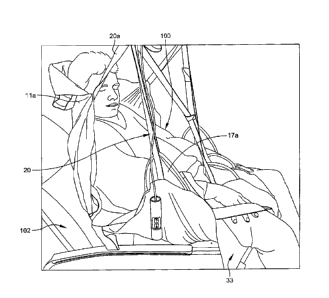
[0037] Referring to Figs. 7 and 8, inflatable mattress-sling 2 may be used
to allow
for easy positioning and movement of patients as follows. Straps 20a and 20b
fasten to
shoulders 11a and 11b are similarly attached to derrick 106 so as to secure
the upper
portion of torso pad 32 against the back of patient 100. Once in this
position, derrick
106 may be moved upwardly, thereby causing mattress-sling 2 to cradle patient
100
and support patient 100's weight as it is lifted from chair 102.
Advantageously, the off-
set positioning of the anchor straps significantly diminishes creasing or
folding of the leg
portions of mattress-sling 2, thereby removing possible pain causing stress
concentrations during lifting. In many embodiments, strap hangers 17a, 17b and
17c,
17d are offset longitudinally from one another along each of legs 33 and 35.
Unlike the
prior art, this relative location of the strap anchors provides for an equal
distribution of
weight across panel 4 of legs 33 and 35, once again reducing creasing or
folding of the
fabric and subsequent pain or injury to the patient.
[0038] Once patient 100 cradled in mattress-sling 2 is moved via derrick
106 from
chair 102 onto a suitable surface, e.g., a bed, the foregoing procedure may be
reversed
so as to lower patient 100 onto the bed's surface. Once in this position, an
air hose 38
may be connected to nozzle 37 so as to introduce air under pressure into the
interior of
mattress-sling 2 so as to inflate mattress-sling 2, thereby forming a transfer
mattress for
movement laterally of the patient on the bed or from the bed to a similar
height flat
surface.
[0039] It is to be understood that the present invention is by no means
limited
only to the particular constructions herein disclosed and shown in the
drawings, but also
comprises any modifications or equivalents within the scope of the claims.
11