Note: Descriptions are shown in the official language in which they were submitted.
CA 02827183 2013-09-12
=
FIRE-RATED WALL CONSTRUCTION PRODUCT
BACKGROUND OF THE INVENTION
Field of the Invention
This application is directed toward fire-rated wall construction components
for use in
building construction.
Description of the Related Art
Fire-rated wall construction components and assemblies are commonly used in
the
construction industry. These components and assemblies are aimed at preventing
fire, heat, and
smoke from leaving one portion of a building or room and entering another,
usually through vents,
joints in walls, or other openings. The components often incorporate the use
of a fire-retardant
material which substantially blocks the path of the fire, heat, and smoke for
at least some period of
time. Intumescent materials work well for this purpose, since they swell and
char when exposed to
flames, helping to create a barrier to the fire, heat, and smoke.
One example of a fire-rated wall construction component is the FirestikTM
design. The
FirestikTM design incorporates a metal profile with a layer of intumescent
material on its inner
surface. The metal profile of the FirestikTM design is independently and
rigidly attached to a wall
component, such as the bottom of a floor or ceiling, and placed adjacent to
other wall components,
such as a stud and track. The intumescent material, which is adhered to the
inner surface of the
metal profile, faces the stud and track, and the space created in between the
intumescent material
and the stud and track allows for independent vertical movement of the stud in
the track when no
fire is present.
When temperatures rise, the intumescent material on the FirestikTM product
expands rapidly.
This expansion creates a barrier which encompasses, or surrounds the stud and
track and
- 1 -
LEGAL_21279788.1
CA 02827183 2013-09-12
substantially prevents fire, heat, and smoke from moving through the spaces
around the stud and
track and entering an adjacent room for at least some period of time.
While the FirestikTM design serves to prevent fire, heat, and smoke from
moving through
wall joint openings, it also requires independent attachment and proper
spacing from wall
components. It would be ideal to have wall components and systems which
themselves already
incorporate a fire-retardant material.
An additional problem regarding current fire-rated wall components concerns
ventilation.
Exterior soffits for balconies or walkways are required to be fire rated.
However, these soffits need
to be vented to prevent the framing members from rotting. The rot is caused
when airflow is taken
away and condensation forms inside the framing cavity. The moisture from the
condensation attacks
the framing members and destroys them from the inside out. In many cases, the
deterioration is not
noticed until the framing is completely destroyed. Therefore, a fire-rated
wall component is needed
which accommodates proper ventilation during times when no fire or elevated
heat is present, and
seals itself when fire or elevated heat is present.
SUMMARY OF THE INVENTION
The present application is directed toward fire-rated wall construction
components and
systems for use in building construction. The term "wall," as used herein, is
a broad term, and is
used in accordance with its ordinary meaning. The term may include, but is not
limited to, vertical
walls, ceilings, and floors. It is an object of the application to provide
wall components and systems
which have fire-retardant characteristics. It is also an object of the
application to provide wall
components and systems which allow for needed ventilation during times when no
fire or elevated
heat is present.
To achieve some or all of these objects, an embodiment of a wall system is
provided that
takes two separate components, a wall component and intumescent material, and
combines the two
for use in building construction. The embodiment includes at least one surface
on a wall component
capable of accepting intumescent material. In some embodiments, the outer
surface of the
intumescent material sits flush with a second surface of the wall component.
This allows the wall
component to retain its general shape and geometry without creating unwanted
edges, protrusions,
- 2 -
LEGAL_212797881
CA 02827183 2013-09-12
or uneven shapes. It also removes the need for a separate product or wall
component to be installed
outside or adjacent to a stud or track. In other arrangements, it may be
desirable for the outer surface
of the intumescent material to extend above the second surface of the wall
component to, for
example, facilitate contact between the intumescent material and another
component or surface. In
some arrangements, it may be desirable for the outer surface of the
intumescent material to be
positioned below the second surface of the wall component.
In an embodiment which resembles a vent or ventilation system, the intumescent
material is
positioned within an interior space of a vent. The vent may include first and
second components,
each including vent holes. In some arrangements, the intumescent material may
include a set of
holes, especially when the intumescent material is covering vent holes of the
vent component(s).
The term "holes," as used herein, is a broad term, and is used in accordance
with its ordinary
meaning. The term includes, but is not limited to, holes, mesh, and slots.
When the vent is in use, the
holes in the vent surface (and, in some arrangements, the holes in the
intumescent material) allow
for continuous air flow through the vent. If provided, the holes in the
intumescent material and the
holes in the vent surface need not match up co-axially, as long as air flow is
permitted. In some
embodiments, the holes in the intumescent material may line up co-axially with
the holes in the vent
surface. Additionally, in some embodiments a flat strap may define a portion
of the vent and may sit
above the intumescent material. The flat strap may be a discrete piece
attached separately, or may
already be an integral part of the vent itself. The flat strap has its own set
of holes which, when in
use, allow for continuous air flow through the vent. In some embodiments the
holes may be aligned
co-axially with both the holes in the vent surface and the holes in the
intumescent material. By
having holes in both the vent and strap, air can flow through the vent,
intumescent material (in some
embodiments), and strap during times when there is no fire or elevated heat.
When the temperature
rises, however, the intumescent material will expand quickly and block air
pathways. In this manner,
the entire vent will be sealed, substantially preventing fire, heat, and smoke
from reaching other
rooms or parts of the building for at least some period of time. The
intumescent material may be a
strip of material that can be handled separately from the vent, or may be a
layer of material applied
to the vent (e.g., sprayed or painted onto the vent), among other
possibilities.
In yet another embodiment, a wall system is provided which comprises a first
wall
component, a second wall component, a flat strap of material attached to the
first wall component,
and a strip of fire-retardant material located on the flat strap.
-3 -
LEGAL_21279788.1
CA 02827183 2013-09-12
In yet another embodiment, a wall system is provided which comprises a deck
with a flute, a
wall generally aligned along the length of the flute, a flat strap located
between the deck and the
wall and attached to the deck, and a pair of fire-retardant material strips,
one on either side of the
flute, located on the flat strap between the flat strap and the deck.
In yet another embodiment, a pre-formed fire-retardant sponge is provided for
use in a flute
of a fluted deck, the sponge comprising a body having substantially the same
shape as the shape of a
flute of a fluted deck, the body being formed of compressible material and
having at least one layer
of fire-retardant material, and the body having an uncompressed size larger
than that of the size of
the flute.
In yet another embodiment, a fire-retardant wall system is provided comprising
a track for
receiving wall studs, the track comprising a web and flange, the track further
comprising at least one
surface for accepting fire-retardant material thereon, the at least one
surface configured such that
when the track is attached to a deck, the fire-retardant material can expand
and seal any gaps present
between the track and the deck when the fire retardant material is exposed to
elevated heat. The
system further comprises at least one wall stud received within the track, at
least one piece of
drywall attached to the at least one wall stud, and an elongate protrusion or
sealing element located
along the flange.
In yet another embodiment, a fire-retardant wall system is provided comprising
a track for
receiving wall studs, the track comprising a web and flange, the track further
comprising at least one
surface for accepting fire-retardant material thereon, the at least one
surface configured such that
when the track is attached to a deck, the fire-retardant material can expand
and seal any gaps present
between the track and the deck when the fire retardant material is exposed to
elevated heat. The
system further comprises fire-retardant material attached to the at least one
surface of the track, the
fire-retardant material being located along at least a portion of the flange,
at least one wall stud
received within the track, at least one piece of drywall attached to the at
least one wall stud, and an
elongate protrusion located along the flange between a free end of the flange
and an edge of the fire-
retardant material.
- 4 -
LEGAL_21279788.1
CA 02827183 2013-09-12
In yet another embodiment, a wall system having fire-retardant characteristics
is provided,
the system comprising a wall component comprising sturdy material and further
comprising a first
surface configured to accept fire-retardant material thereon, the first
surface positioned such that
when the wall component is affixed to an exposed surface of a second wall, the
fire-retardant
material applied to the wall component would be positioned proximal the second
wall so as to
permit expansion of said fire-retardant material and resultant sealing of any
gap between said wall
component and the exposed surface of said second wall when exposed to elevated
heat or fire.
In yet another embodiment, a method of substantially preventing fire, heat,
and/or smoke
from moving through or around wall components for at least some period of time
is provided, the
method comprising providing a wall component with a first surface capable of
receiving fire-
retardant material, providing a fire-retardant material in a bonded fashion to
the first surface, and
installing the wall component and fire-retardant material so as to permit
expansion of said fire-
retardant material and resultant sealing of the plurality of holes in said
wall component when
exposed to elevated heat or fire.
Additional embodiments involve individual components of the systems described
above,
such as the individual flat straps, tracks or vent components, for example. In
addition, embodiments
of the present invention include methods of manufacturing the wall systems,
vents or vent systems
described above. Furthermore, other embodiments involve methods of assembling
the wall systems,
vents or vent systems described above.
BRIEF DESCRIPTION OF THE DRAWINGS
These and other features, aspects and advantages of the various devices,
systems and
methods presented herein are described with reference to drawings of certain
embodiments, which
are intended to illustrate, but not to limit, such devices, systems, and
methods. The drawings include
thirteen (13) figures. It is to be understood that the attached drawings are
for the purpose of
illustrating concepts of the embodiments discussed herein and may not be to
scale.
Figure 1 illustrates a cross-sectional view of an embodiment of a fire-rated
wall component
connected to a floor and stud element.
-5 -
LEGAL_21279788.1
CA 02827183 2015-09-25
Figure 2 illustrates a perspective view of an embodiment of a fire-rated wall
component
with arcuate or curved portions.
Figure 3 illustrates a perspective view of an embodiment of a fire-rated wall
component
with arcuate portions, including intumescent material.
Figure 4 illustrates a perspective view of an embodiment of a fire-rated wall
component
with channels or slots and intumescent material in the slots.
Figures 5A and 5B illustrate perspective views of embodiments of a fire-rated
wall
component including holes for ventilation.
Figures 6A and 6B illustrate perspective views of an embodiment of a fire-
rated wall
component including holes for ventilation.
Figures 7A and 7B illustrate perspective views of an embodiment of a fire-
rated wall
component including holes for ventilation.
Figure 8 illustrates a cross-sectional view of an embodiment of a fire-rated
wall component
with intumescent material on its top surface.
Figure 9 illustrates a cross-sectional view of an embodiment of a fire-rated
wall component
with intumescent material on both its top and side surfaces.
Figure 10A illustrates a cross-sectional view of an embodiment of a wall
system with a flat
strap.
Figure 10B illustrates a cross-sectional view of the track portion of the
embodiment of
Figure 10A prior to installation.
Figure 10C illustrates a cross-sectional view of a portion of the embodiment
of Figure 10A.
Figure 10D illustrates the embodiment of Figure 10A, except with the fasteners
moved in.
Figure 11 illustrates a perspective view of an embodiment of a fire sponge.
Figure 12A illustrates a cross-sectional view of an embodiment of a wall
system which
incorporates the fire sponge of Figure 11.
Figure 12B illustrates a cross-sectional view of a portion of the embodiment
of the wall
system of Figure 12A.
Figure 13 illustrates a cross-sectional view of an embodiment of a wall system
with a
protruding groove to inhibit movement of air.
- 6 -
CA 02827183 2013-09-12
DETAILED DESCRIPTION OF THE PREFERRED EMBODIMENTS
The preferred embodiments of the present invention are directed toward fire-
rated wall
construction components and systems for use in building construction. Fire-
rated wall construction
components and assemblies are commonly used in the construction industry.
These components and
assemblies are aimed at preventing fire, heat, and smoke from leaving one
portion of a building or
room and entering another, usually through vents, joints in walls, or other
openings. The
components and assemblies often incorporate the use of some sort of fire-
retardant material, such as
intumescent material, which substantially blocks the path of the fire, heat,
and smoke for at least
some period of time.
Figure 1 illustrates a cross-sectional view of an embodiment of a fire-rated
wall component
connected to a floor or ceiling element 18 and stud element 20. The wall
component 10 is used as
a track for holding a stud within a vertical wall, and may include slots along
its sides. The slots
provide areas to accommodate fasteners for connection with the studs and allow
for vertical
movement of the attached studs during an earthquake or some other event where
vertical movement
of the studs is desired.
As can be seen in Figure 2, wall component or header track 10 has both a flat
top surface 28
and two arcuate surfaces 24 and 26. Top surface 28 is flat for ease of
attachment to the bottom
surface of a floor or ceiling 18. The two arcuate surfaces 24 and 26 are
designed to receive
intumescent material. The arcuate nature of the surfaces 24 and 26 can
encourage the intumescent
material, in at least some embodiments, to expand in a more radial direction
from the top of the wall
component 10 when subjected to elevated levels of heat, thereby filling in a
larger area between and
alongside the header track and floor 18. In other embodiments, the surfaces
24, 26 can have other
shapes or configurations.
The intumescent material, identified as 12 and 14 in Figures 1 and 3, is
bonded to arcuate
surfaces 24 and 26. The term "bonded," as used herein, is a broad term, and is
used in accordance
with its ordinary meaning. The term includes, but is not limited to,
mechanically bonded or bonded
using adhesive. In some embodiments, when the intumescent material is bonded,
an outer surface of
the intumescent material will be flush with top surface 28. This allows top
surface 28 to remain
flush, or at least partially flush, with the bottom of floor element 18, and
may aid in the installation
- 7 -
LEGAL_21279788 1
CA 02827183 2013-09-12
of wall component 10 to a floor or ceiling. This flush attachment additionally
allows the wall
component 10 to retain a fluid or smooth-shaped geometry free of added edges,
overlaps, or
protrusions. In doing so, the area of contact between the intumescent material
and the floor element
18 can inhibit air and sound from moving past the header track 10. In other
arrangements, it may be
desirable for the outer surface of the intumescent material to extend above
the top surface 28 to, for
example, ensure contact between the intumescent material and the floor element
18. In some
arrangements, it may be desirable for the outer surface of the intumescent
material to be positioned
below the second surface of the wall component.
By incorporating intumescent material onto a wall component such as a track
for studs in the
manner shown, it becomes unnecessary to use or attach additional features or
devices to the wall
component. Instead, when the temperature rises near the wall component 10, the
intumescent
material 12 and/or 14 will heat up. At some point when the intumescent
material becomes hot
enough, it will quickly expand to multiple times its original volume. This
intumescent material will
expand towards the floor or ceiling element 18 and outwards toward any open
space. This helps to
substantially prevent fire, heat, and smoke from moving past, through, or
around wall component 10
and stud 20 for at least some period of time.
Figure 4 illustrates another embodiment of a fire-rated wall component 32. In
this
embodiment, the wall component 32 again takes the form of a track member for
use in holding studs
in place within a vertical wall. However, here the wall component 32 has two
slots or channels,
shown as 34 and 36, wherein the intumescent material 40 and 42 is attached. As
can be seen in the
drawing, the top surface layers of intumescent material 40 and 42 are flush
with the top surface 38
of wall component 32. This allows the top surface 38 of wall component 32 to
maintain a smooth
geometry, which may aid in the installation of wall component 32 to a floor,
ceiling or intersecting
wall. This flush attachment additionally allows the wall component 10 to
retain a fluid or smooth-
shaped geometry free of added edges, overlaps, or protrusions. However, a
flush attachment as
described above is not essential to the success of the present invention.
It is possible that more than two slots could be used in the type of
embodiment shown in
Figure 4, or even as few as one. The purpose of having the intumescent
material located in the slots
34 and 36 is to create fire protection areas. When the intumescent material 40
and 42 becomes hot, it
will expand rapidly into the open areas around it. Much as in the embodiment
shown in Figures 1-3,
- 8 -
LEGAL_21279788.1
CA 02827183 2013-09-12
this expansion will help to create a barrier, or seal, substantially
preventing fire, heat, and smoke
from moving from one area of a building to another for at least some period of
time.
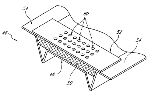
Figures 5A and 5B illustrate other embodiments of a fire-rated wall component
46. Here, the
wall component takes the form of a soffit vent. The wall component 46 has a
lower ventilation area
48 which includes a set or series of ventilation holes. These holes, which are
hidden from view in
Figures 5A and 5B, but are shown in Figure 6B, allow air and other matter to
travel between floors
and rooms in a building, or between the outside of a building and the interior
of a building.
As can be seen in Figure 5A, a strip of intumescent material 50 is provided
within the vent
46 and above ventilation area 48. The intumescent material 50 may be loosely
positioned within the
vent 46 or, as illustrated, may be attached adjacent to one or more components
of the vent 46. The
top surface of the intumescent material is flush with the top surface 54 of
wall component 46. This
allows for easy installation and use of a flat strap 52, which may be a
separate member from the vent
46 or may be integrated with the vent 46. A flush fit, however, is not
essential to the success of the
present invention.
In some arrangements, especially if covering the holes of the ventilation area
48, the
intumescent material 50 may be provided with a series of surfaces defining
holes. These holes are
hidden from view in Figures 5A and 5B but are shown in Figure 6A. The holes
allow air and other
matter to continue to travel between floors and rooms in a building, or
between the outside of a
building and the interior of a building. Flat strap 52 also has a series of
holes 60 located in its center
area. This series of holes, much like the ventilation and intumescent material
holes, allows air and
other matter to travel between floors and rooms in a building, or between the
outside of a building
and the interior of a building.
The intumescent material 50 may occupy a portion or all of the interior space
defined by the
vent 46. In one or more arrangements, the intumescent material 50 occupies
only a portion of the
interior space to facilitate air flow through the vent 46. When the
intumescent material 50 becomes
hot, it will expand to many times its original size into the open areas around
it. Much as in the
embodiments shown in Figures 1-4, this expansion will help to create a
barrier, or seal, inhibiting or
at least substantially preventing fire, heat, and smoke from moving from one
area of a building to
another for at least some period of time.
- 9 -
LEGAL_21279788.1
CA 02827183 2013-09-12
Figures 6A and 6B illustrate another embodiment of a fire-rated wall component
56. In
Figure 6A, intumescent material holes 58 are visible, and the intumescent
material 50 extends along
the sides of vent area 48. When the intumescent material 50 becomes hot, it
expands rapidly, filling
much if not all of the space underneath the flat strap 52. This expansion
substantially cuts off at least
a substantial amount of air movement through the vent surface 48, and inhibits
or at least
substantially prevents fire, heat, and smoke from moving through the vent for
at least some period of
time. As can be seen in the embodiment in Figure 6A, the flat strap 52 is
formed as an integral part
of the wall component 56. In other embodiments, the flat strap 52 may be a
discrete piece attached
separately.
Figure 6B illustrates the bottom view of fire-rated wall component 56. Here,
ventilation
holes 68 can be seen in the vent area 48. The intumescent material 50 is
attached to both the vent
area 48 and along its extended sides. The intumescent material 50 can be a
single piece of material,
or can be made up of several pieces. The intumescent material 50 can be
secured to the strap 52 or
wall component 56 by any suitable means. For example, in one arrangement, the
intumescent
material 50 includes an adhesive backing, which permits the intumescent
material 50 to be secured
to the strap 52 or wall component 56. In an alternative arrangement, the
intumescent material 50
may be secured to the strap 52 or wall component 56 by a mechanical fastener,
such as a screw or
rivet, for example. Other suitable mechanisms or methods may also be used. The
intumescent
material 50 may be secured to the strap 52 or wall component 56 during the
manufacturing process
or in the field.
Figures 7A and 7B illustrate another embodiment of a fire-rated wall component
66. With
reference to Figure 7A, the wall component 66 can include a flat strap 52 with
intumescent material
50 attached underneath, such that the intumescent material faces the inside
area of the vent. In at
least some embodiments the flat strap can comprise 20 gauge sheet metal, and
the intumescent
material can be about 2mm thick and about 1 1/4" wide. Other gauges, sizes,
and shapes are also
possible. The intumescent material can be attached to the flat strap 52 by
various means, including
but not limited to adhesive tape and/or mechanical fasteners. The flat strap
52 can be a discrete piece
attached separately to the top surface 54, or can be formed as an integral
part of .the wall
component, as shown in Figure 6A. In some embodiments, the flat strap 52 can
include expanded
metal lathes along either side with slots or holes 60, and an area in between
for attachment of the
- 10 -
LEGAL_21279788.1
CA 02827183 2013-09-12
intumescent material 50. In some embodiments, the holes 60 can be about 1/4"
wide and about 1 V2"
wide. Other sizes are also possible.
With continued reference to Figure 7A, the wall component 66 can allow air
movement
through the vent when the intumescent material 50 has not expanded. The air
can move through
holes 68 into the open space inside the vent and then out through slots or
holes 60. In at least some
embodiments the holes 68 can be about 1/8" in diameter. Other sizes and shapes
are also possible.
When the intumescent material expands, it can cover up either or both sets of
holes 68, 60, in order
to inhibit fire, heat, and smoke from moving through the vent.
With reference to Figure 7B, in some embodiments the intumescent material can
instead be
placed on the lower portion of the vent itself as opposed to the bottom of the
flat strap 52. Holes 68
can be located on one or both sides of the intumescent material along the
bottom of the vent, and
slots or holes 60 can be located along the flat strap 52. Just as with the
embodiment shown in Figure
7A, the intumescent material 50 can expand to cover up holes 60 and/or 68 when
exposed to
elevated levels of heat, inhibiting fire, heat, and smoke from moving through
the vent. In at least
some embodiments the top of the vent can have at least one end that wraps
about the flat strap 52 to
help hold it in place, as shown in Figure 7B.
In yet other embodiments, the intumescent material, or other fire-retardant
material, can be
sprayed or painted onto one or both sides of the bottom of the vent or onto
the flat strap. The spray
or paint can cover areas which surround the holes 68. When exposed to heat,
the fire-retardant
material can expand to cover the holes 68, thereby inhibiting fire, heat, and
smoke from moving
through the vent.
Figure 8 illustrates another embodiment of a fire-rated wall component 72. In
this
embodiment, the wall component 72 is a track for holding a wall stud 20
beneath a ceiling 18. Here,
the intumescent material 74 is attached to the top surface of the wall
component 72. During
installation, it is possible to install the wall component 72 and intumescent
material 74 to the ceiling
18. In some embodiments, this may be accomplished by threading a screw through
both the wall
component and intumescent material. Additionally, in some embodiments the
intumescent material
may extend down one or both sides of the wall component 72.
- 11 -
LEGAL_21279788.1
CA 02827183 2013-09-12
Figure 9 illustrates another embodiment of a fire-rated wall component 80. In
this
embodiment, the wall component 80 is a track for holding a wall stud. However,
here the
intumescent material 84 extends both along a portion of the top and side
surfaces of the wall
component 80. In particular, intumescent material is provided on the side and
top surfaces of each
comer portion of the wall component 80. In some embodiments, an outer surface
of the intumescent
material 84 may be flush with the top surface 82. In other embodiments, the
intumescent material 84
may extend above the adjacent surfaces of the wall component 80, or may be
positioned below the
adjacent surfaces of the wall component 80.
With reference to Figure 10A, a fire-retardant wall system 110 can comprise a
first wall
component 112, a second wall component 114, a flat strap 116, and at least one
strip of fire-
retardant material 118. In at least some embodiments the first wall component
112 can comprise a
fluted deck such as the one illustrated in Figure 10A. In yet other
embodiments the first wall
component 112 can comprise a floor, ceiling, overhang, or any other type of
wall component.
In at least some embodiments the second wall component 114 can comprise a
track, or
header track, such as the one illustrated in Figure 10A, for retaining wall
studs. The header track can
comprise a slotted header track. In yet other embodiments the second wall
component can comprise
a different type of track or wall component.
With reference to Figures 10A and 10B, the second wall component 114 can
include at least
one gasket 120. The gasket 120 can itself comprise a strip of fire-retardant
material, including but
not limited to intumescent material. In at least some embodiments, the gasket
120 can be adhered to
a surface of the second wall component 114 such that when the second wall
component is attached
to, pressed, and/or placed against the fire strap 116, the gasket or gaskets
120 can form a sound
and/or air seal, inhibiting sound and/or air from moving from one side of the
second wall component
114 to the other. For example, and with reference to Figure 10B, in at least
some embodiments the
gasket can be adhered to the second wall component 114 such that a portion of
it protrudes and/or
extends past an adjacent edge of the second wall component 114. When the
second wall component
114 is pressed against and/or attached to the flat strap 116 or other wall
component, the portion of
the gasket protruding past the edge can be compressed down towards the
adjacent edge of the wall
component 114 in order to form a seal between the flat strap 116 and second
wall component 114.
- 12 -
LEGAL_212797881
CA 02827183 2013-09-12
As described above, this seal and contact can inhibit air and sound from
moving past the second
wall component 114.
The flat strap 116 can be attached to the first wall component, the second
wall component, or
both the first and second wall components. For example, and as illustrated in
Figure 10A, the flat
strap 116 can be attached via fasteners 122 to the first wall component I 12.
In at least some
embodiments, the flat strap 116 can comprise an about 6"- 8" wide 20 gauge
flat strap. The flat strap
116 can be used to cover a portion or all of one or more flutes 124 of the
fluted deck 112, Figure
10A showing a cross-section of the flute 124. Thus, the flat strap 116
provides a surface for the
second wall component 114 to contact when the wall component 114 is generally
aligned with the
length of the flute 124, or when the wall component 114 extends generally
alongside and underneath
the length of the flute 124 as shown in Figure 10A. In other embodiments a
portion or portions of
the wall component 114 can be aligned with a portion of the fluted deck that
does not include the
flute 124.
With reference to Figures 10A-10D, the strip of fire-retardant material 118
can comprise
intumescent material, which expands when subjected to elevated levels of heat,
or can comprise
other types of fire retardant material. In some embodiments an about 1/2"
thick strip of material can
be used. Other thicknesses are also possible.
In at least some embodiments, and with reference to Figure 10C, the strip of
fire-retardant
material 118 can be adhered to the flat strap so that it rests between the
flat strap 116 and first wall
component 112. In at least some embodiments, the fire-retardant system 110 can
include two or
more strips of fire-retardant material 118. In some embodiments, the strips of
fire-retardant material
118 can be located approximately 1/4" in from the ends of the flat strap 116.
For example, and with
reference to Figure 10A, the system 110 can include one strip of fire-
retardant material 118 located
on each side of the second wall component 114 and on each side of the flute
124.
In at least some embodiments, and with reference to Figures 10A and 10C, the
strip of fire-
retardant material 118 can include a preformed fastener hole for insertion of
the fastener 122. The
fastener 122 can be fastened through the fire-retardant material 118. A washer
117 can be used
between a head of the fastener 122 and the flat strap 116 to help secure the
flat strap 116. The
fastener 122 can help to secure the fire-retardant material in place. In other
embodiments, and with
- 13 -
LEGAL_21279788.1
CA 02827183 2013-09-12
reference to Figure 10D, the fastener 122 can be located adjacent or inside of
the fire-retardant
material 118 along the flat strap 116.
In some embodiments, the fasteners 122 can be located every 12" on center
along the length
of the flat strap. In order to locate the areas for attachment, in at least
some embodiments, the flat
strap 116 can include the preformed fastener hole, as described above, or
other suitable markings.
For example, in some embodiments the flat strap can be indented, scored, or a
laser or inkjet (or
other suitable) line can be placed along the length of the flat strap 116, to
help locate where the
fasteners 122 should be installed through the fire-retardant material and into
the wall component
112.
With continued reference to Figures 10A-10D, the fire-retardant system 110 can
inhibit fire,
smoke, air, sound, and/or debris from moving from one side of the second wall
component 114 to
the other (e.g. from one room to another inside a building). The strip or
strips of fire-retardant
material 118 and/or 120 can act as gaskets, preventing air and/or sound from
moving past the system
110. At the same time, when the strips 118 and/or 120 are exposed to elevated
levels of heat, they
can expand and fill any gaps left between the flat strap 116 and first and
second wall components
112, 114.
The flat strap 116 with fire-retardant material 118 can be used with other
systems, decks,
tracks, or wall components as well. Thus, it is not limited to use with a
fluted wall component and/or
header track, as illustrated in Figures 10A-10D.
With reference to Figures 11 and 12, a fire sponge 130 can be used to prevent
the spread of
fire, heat, and/or debris. The fire sponge 130 can be sized and shaped so that
it is custom-made for
particular sized and shaped spaces. For example, the fire sponge 130 can be
shaped so that it fits
snugly into the hollow area or areas of a fluted deck.
With continued reference to Figure 11, the fire sponge 130 can comprise an
inner layer of
material 132, such as for example mineral wool. The inner layer 132 can be
compressible, so that
the entire sponge 130 can be compressed into an area smaller than the volume
of the fire sponge 130
itself. The fire sponge 130 can further comprise another layer of material 134
outside of the inner
layer 132. In some arrangements, the layer of material 134 can be the
outermost layer, and in other
- 14 -
LEGAL_21279788.1
CA 02827183 2013-09-12
arrangements can be an intermediate layer. In at least some embodiments the
layer of material 132
can comprise fire-retardant material, including but not limited to intumescent
material. In at least
some embodiments, the fire sponge 130 can further comprise an additional outer
layer of material
136, including but not limited to latex smoke seal. In one preferred
embodiment, the outer layer of
latex smoke seal can range between 1/16"- 1/8" in thickness. This outer layer
of latex smoke seal
can give the fire sponge 130 a flexible, yet durable shape. For example, the
latex can prevent wear
and tear during shipping and/or installation, and can also prevent smoke from
moving through the
fire sponge 130.
With reference to Figures 11 and 12A, the custom-made and pre-shaped fire
sponges 130 can
be made to have a trapezoidal cross-section so as to fit into the generally
trapezoidal-shaped flutes
commonly found in decks. In at least some embodiments, the trapezoidal-shaped
fire sponge 130
can have widths which are larger than the widths of the flute. Other shapes
and geometries are also
possible. In some embodiments, the fire sponge 130 can be made at least in
part of a compressible
material, and its initial manufactured size can be larger than that of the
flute 124. This allows the
sponge 130 to be compressed to fit inside the flute 124, and once inside to
expand and hold itself in
place. For example, in at least one embodiment, the fire sponge 130 can be
made to compress by
approximately 30% of its initial volume to fit inside the flute 124. Other
percentages and/or ranges
of percentages are also possible.
Custom-made and pre-shaped fire sponges can reduce the amount of time required
for fire-
proofing the interior of a building, particularly if the size of the fluted
wall components is known.
For example, instead of placing or stuffing numerous, similar-shaped fire
blocks or material into a
hollow area and then using an airless sprayer to spray latex smoke sealer, a
single custom-shaped
fire sponge as described above can be used.
With continued reference to Figure 12A, a fire-retardant wall system 210 can
include a first
fluted wall component 212 and a second,. attached wall component 214. In at
least some
embodiments the first fluted wall component 212 can comprise a fluted deck,
and can include
hollow areas for insertion of a fire sponge or sponges 130. In at least some
embodiments, the
sponges 130 can be inserted after the second wall component 214 has been
attached to the fluted
wall component 212.
- 15 -
LEGAL_21279788 1
CA 02827183 2013-09-12
With reference to Figures 12A and 12B, in at least some embodiments the second
wall
component 214 can comprise a header track, which may be slotted or unslotted.
In some
embodiments the track can have a U-shape. In other embodiments it can have a J-
shape. Other
shapes are also possible. In at least some embodiments the track can be used
for shaft areas in
buildings, including but not limited to elevator shafts. In such arrangements,
the structures for
sealing with wallboard members described below may be provided on only one
side of the track
because the shaft side typically does not include wallboard.
With continued reference to Figures 12A and 12B, the illustrated header track
is slotted and
can comprise a strip or strips of fire-retardant material 216, including but
not limited to intumescent
material, along at least one flange. The strip of fire-retardant material 216
can be located along an
area of the flange adjacent and/or proximal to the series of slots 218 in the
flange. As illustrated in
Figure 12A, the second wall component 214 can extend along the bottom of the
fluted wall
component 212, generally perpendicular to the lengths of the flutes 224.
The second wall component 214 can further comprise a strip or strips of a
sealing element
220 located between the strip 216 and series of slots 218, and also between
the strip 216 and a piece
or pieces of an outer wallboard member, such as a sheet of drywall 222, or
other exterior material.
The sealing element 220 can be a separate component from the track 214 such
as, for example,
caulk, foam or tape, and can be used to prevent or inhibit air from moving
between the drywall and
the second wall component 214. Alternatively, as described below, the sealing
element can be
formed by the track itself. For example, and with reference to Figure 12B, the
sealing element 220
can extend away from the flange and towards the drywall 222 such that the
drywall 222 is able to
rest against a portion of the sealing element 220. This configuration can help
prevent air from
moving between the drywall 222 and the track, while at the same time
preventing the drywall from
covering up or moving over and interfering with the fire-retardant material
216.
With reference to Figure 13, other structures or embodiments for preventing
unwanted
airflow are also possible. For example, a fire-retardant wall system 310 can
comprise a slotted or
unslotted track 312. In the illustrated arrangement, the track 312 is slotted.
The slotted track 312 can
comprise at least one surface for accepting fire-retardant material 314
thereon. The at least one
surface can be configured such that when the track is attached to a first wall
component, the fire-
retardant material 314 can expand and seal a gap between the slotted track 312
and first wall
- 16 -
LEGAL_21279788.1
CA 02827183 2013-09-12
component when the fire-retardant material is exposed to elevated heat. The
track 312 can also
comprise an elongate protrusion or rib 316 located along at least a portion of
one or more of the
flanges of the track and proximal the at least one surface, as illustrated in
Figure 13.
In at least some embodiments, the elongate protrusion 316 can have a generally
v-shaped
cross section. Other cross-section shapes are also possible, for example, the
protrusion 316 can be
generally u-shaped or trapezoidal in shape. The elongate protrusion 316 can
act as both a boundary
area for the fire-retardant material, as well as a resting and/or attachment
location for a piece of
drywall 318, or other exterior material. The drywall can rest and/or remain in
contact with the
elongate protrusion 316, thereby blocking air from moving between the drywall
318 and slotted
track 312. At the same time, the elongate protrusion 316 can help prevent the
drywall 318 from
contacting and/or interfering with the fire-retardant material 314.
In some embodiments, the drywall is fastened to a stud within the slotted
track 312. The
head portion 320 of the fastener can tend to bow out the drywall, leaving a
gap at the top of the
drywall to allow air, sound, or debris in general to move between the drywall
and the slotted track
312. The sealing element 220 and/or elongate protrusion 316 can have depths
large enough such that
even if the drywall is bowed out, the drywall remains in contact with the
sealing element 220 and/or
elongate protrusion 316. For example, in some embodiments, the sealing element
220 and/or
protrusion 316 can have depths at least equivalent to the depth of the
fastener head 320. As
described above, the track can be configured for use in a shaft wall
application. In such an
arrangement, the track may include fire-retardant material 216 or 314 and the
sealing element 220 or
protrusion 316 on only one side (i.e., the side opposite the shaft). The
flange of the track facing the
shaft may be the same or a different length (shorter or longer) than the
opposite flange. In some
applications, it may be desirable for the shaft flange to be longer than the
opposite flange.
The present application does not seek to limit itself to only those
embodiments discussed
above. Other embodiments resembling tracks, vents, or other wall components
are possible as well.
Various geometries and designs may be used in the wall components to
accommodate the use of
fire-retardant material. Additionally, various materials may be used. In at
least some embodiments
the wall component and wall system materials can comprise steel, iron, or
other material having at
least some structural capacity. The fire-retardant materials can comprise
intumescent material, such
- 17 -
LEGAL21279788 1
CA 02827183 2013-09-12
as for example BlazeSealTM, or some other material which accomplishes the same
purposes as those
described above.
Although these inventions have been disclosed in the context of certain
preferred
embodiments and examples, it will be understood by those skilled in the art
that the present
inventions extend beyond the specifically disclosed embodiments to other
alternative embodiments
and/or uses of the inventions and obvious modifications and equivalents
thereof. In addition, while
several variations of the inventions have been shown and described in detail,
other modifications
will be readily apparent to those of skill in the art based upon this
disclosure. It is also contemplated
that various combinations or sub-combinations of the specific features and
aspects of the
embodiments can be made, and should be understood that various features and
aspects of the
disclosed embodiments can be combined with or substituted for one another in
order to form varying
modes of the disclosed inventions.
- 18 -
LEGAL_21279788 1