Note: Descriptions are shown in the official language in which they were submitted.
=
PERCUTANEOUS ARTHRODESIS METHOD AND SYSTEM
Field of the Invention
[0001] Presented herein is a percutaneous arthrodesis method and system. More
specifically, a method and system for minimally invasive 3-point fusion is
presented.
Background of the Invention
[0002] There are several procedures available to patients with degenerative
spine
conditions. For example, Anterior Lumbar Interbody Fusion ("ALIF") has been
performed by surgeons since the 1950's. In an ALIF procedure, the disc space
is fused
by approaching the spine through the abdomen. In the ALIF approach, a three-
inch to
five-inch incision is made on the left side of the abdomen and the abdominal
muscles
are retracted to the side. Since the anterior abdominal muscle in the midline
(rectus
abdominis) runs vertically, it does not need to be cut and easily retracts to
the side. The
abdominal contents lay inside a large sack (peritoneum) that can also be
retracted, thus
allowing the spine surgeon access to the front of the spine without actually
entering the
abdomen. There is also a less popular transperitoneal approach that accesses
the
spine through the abdomen. This adds a lot of unnecessary morbidity to the
procedure
and therefore is used much less often.
[0003] Another technique is called Posterior Lumbar Interbody Fusion ("PLIF").
In the
PLIF approach, the spine is accessed through a three-inch to six-inch long
incision in
the midline of the back and the left and right lower back muscles are stripped
off the
lamina and spinous process on both sides and at multiple levels. After the
spine is
approached, the lamina and spinous process is removed, which allows
visualization of
the nerve roots. The facet joints, which are directly over the nerve roots,
may then be
undercut to give the nerve roots more room. The nerve roots are then retracted
to one
side and the disc space is cleaned of the disc material. A bone graft, or an
interbody
cage, is then inserted into the disc space and the bone grows from vertebral
body to
vertebral body.
[0004] Still another procedure is a Transforaminal Lumbar Interbody Fusion
("TLIF"). By
1
CA 2827201 2017-12-19
removing the entire facet joint, visualization into the disc space is improved
and more
disc material can be removed. It should also provide for less nerve
retraction. Because
one entire facet is removed, it is only done on one side. Removing the facet
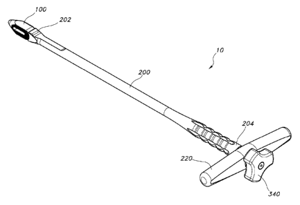
joints on
both sides of the spine would result in too much instability. With increased
visualization
and room for dissection, a larger implant and/or bone graft can be used.
Although this
has some improvements over a PLIF procedure, the anterior approach, in most
cases
still provides the best visualization, most surface area for healing, and the
best
reduction of any of the approaches to the disc space.
[0005] There are other approaches know in the art, as well. For instance,
Direct Lateral
Interbody Fusion, Axial Lumbar Interbody Fusion using a transsacral approach,
and the
like. Those skilled in the art will appreciate that these and other known
procedures have
benefits, as well as disadvantages.
[0006] There are also many types of stabilization systems available. One type
of spinal
stabilization system includes screws and connecting rods which can be used for
stabilizing many spinal conditions including, for example, degenerative disc
disease,
scoliosis, spondylolithisis and spinal stenosis. In these systems, a bone
screw (e.g.,
pedicle screw) is typically anchored into each vertebral body to be stabilized
and a rigid
connecting rod mounted to the screws to fix the vertebrae in a particular
relative
position.
[0007] Another type of spinal stabilization system includes interbody
implants. Some of
these implants are bone, PEEK, solid titanium or similar non-bone implant
material and
some are hollow implants that provide for inclusion of a bone graft or other
suitable
material to facilitate bony union of the vertebrae.
[0008] Interbody implants can be inserted into the disc space through an
anterior,
posterior or lateral approach. In some systems, the implants are inserted into
a bore
formed between adjacent vertebral bodies in the cortical endplates and can
extend into
the cancellous bone deep to the cortical endplates. Implant size is typically
selected
such that the implants force the vertebrae apart to cause tensing of the
vertebral
annulus and other soft tissue structures surrounding the joint space, Tensing
the soft
2
CA 2827201 2017-12-19
tissues surrounding the joint space results in the vertebrae exerting
compressive forces
on the implant to maintain the implant in place.
[0009] Accordingly, there is a continuing need for improved vertebral
stabilizing devices
and methods. The system and apparatuses described herein are directed to
addressing
these needs.
SUMMARY
[0010] Presented herein are a system and method for percutaneous fusion to
correct
disc compression, In one aspect, the system comprises an implant defining at
least one
implant aperture, an elongate cannulated insertion tool defining an interior
insertion tool
pathway, and an elongate lockshaft positioned therein the insertion tool
pathway and
defining a longitudinal interior lockshaft pathway.
[0011] The method comprises several steps, which may or may not be performed
in the
particular order discussed. As one skilled in the art can appreciate, the
methods herein
are not meant to be limited and only serve as a description of the method in
its best
known manner.
[0012] The method, in one aspect, comprises making an incision to access a
desired
spinal motion segment, locating a path to the disc space at the desired target
level,
inserting a guide wire, inserting a spinal implant into the disc space at a
desired
position, removing the guide wire, and fixating a portion of the desired
spinal motion
segment.
BRIEF DESCRIPTION OF THE DRAWINGS
[0013] These and other features of the preferred embodiments of the present
invention
will become more apparent in the detailed description in which reference is
made to the
appended drawings wherein:
[0014] Fig. 1 is a perspective view of one aspect of an Lumbar Interbody
Fusion
3
CA 2827201 2017-12-19
system;
[0015] Fig. 2 is a partially exploded perspective view of the Lumbar Interbody
Fusion
system of Fig. 1;
[0016] Fig. 3 is a side elevational view of the Lumbar Interbody Fusion system
of Fig. 1;
[0017] Fig. 4 is a cut-away side elevational view Lumbar Interbody Fusion
system of
Fig. 1 , cut along line 4-4 of Fig. 3;
[0018] Fig. 5 is a plan view of the Lumbar Interbody Fusion system of Fig. 1;
[0019] Fig. 6 is a perspective view of one aspect for an implant used in a
Lumbar
Interbody Fusion system;
[0020] Fig. 7 is a plan view of the implant of Fig. 6;
[0021] Fig. 8 is front elevational view of the implant of Fig. 6;
[0022] Fig. 9 is a rear elevational view of the implant of Fig. 6;
[0023] Fig. 10 is a side elevational view of the implant of Fig. 6;
[0024] Fig. 11 is a perspective view of one aspect for an implant used in a
Lumbar
Interbody Fusion system;
[0025] Fig. 12 is a plan view of the implant of Fig. 11;
[0026] Fig. 13 is front elevational view of the implant of Fig. 11;
[0027] Fig. 14 is a rear elevational view of the implant of Fig. 11;
[0028] Fig. 15 is a side elevational view of the implant of Fig. 11;
[0029] Fig. 16 is a perspective view of one aspect of a percutaneous
arthrodesis
method, showing the step of positioning a nerve monitoring probe with a
transfer sleeve
through Kambin's triangle;
[0030] Fig. 17 is a perspective view of the method of Fig. 16, showing the
step of
advancing the transfer sleeve to contact a portion of the annulus for removal
of the
probe;
4
CA 2827201 2017-12-19
[0031] Fig. 18 is a perspective view of the method of Fig. 16, showing the
step of
removing the nerve monitoring probe, leaving the transfer sleeve in place;
[0032] Fig. 19 is a perspective view of the method of Fig. 16, showing the
step of
inserting a guide wire through the transfer sleeve to maintain a path to the
disc space;
[0033] Fig. 20 is a perspective view of the method of Fig. 16, showing the
step of
removing the transfer sleeve and leaving the guide wire in place;
[0034] Fig. 21 is a perspective view of the method of Fig. 16, showing the
step of
advancing a dilator over the guide wire;
[0035] Fig. 22 is a partially transparent perspective view of the method of
Fig. 16,
showing the step of pushing a dilator into the disc space to distract the
vertebral bodies;
[0036] Fig. 23 is a partially transparent perspective view of the method of
Fig. 16,
showing the step of positioning an access portal into the disc space;
[0037] Fig. 24 is a partially transparent perspective view of the method of
Fig. 16,
showing the step of removing the dilator and the guide wire, leaving the
access portal in
place;
[0038] Fig. 25 is a partially transparent perspective view of the method of
Fig. 16,
showing the step of performing a discectomy and decorticating the vertebral
endplates
by first drilling to access the nucleus;
[0039] Fig. 26 is a partially transparent perspective view of the method of
Fig. 16,
showing the step of performing a discectomy and decorticating the vertebral
endplates
by rotating a disc shaper;
[0040] Fig. 27 is a partially transparent perspective view of the method of
Fig. 16,
showing the step of performing a discectomy and decorticating the vertebral
endplates
by grasping disc material with a Pituitary rongeur;
[0041] Fig. 28 is a partially transparent perspective view of the method of
Fig. 16,
showing the step of performing a discectomy and decorticating the vertebral
endplates
CA 2827201 2017-12-19
by using a disc cutter;
[0042] Fig. 29 is a partially transparent perspective view of the method of
Fig. 16,
showing the step of introducing a bone graft through a portal using a tube and
plunger
system;
[0043] Fig. 30 is a partially transparent perspective view of the method of
Fig. 16,
showing the step of re-introducing a guide wire through the access portal;
[0044] Fig. 31 is a perspective view of the method of Fig. 16, showing the
removal of
the access portal, leaving the guide wire in place;
[0045] Fig. 32 is a partially transparent perspective view of the method of
Fig. 16,
showing the step of using the guide wire for insertion of a trial implant;
[0046] Fig. 33 is a partially transparent perspective view of the method of
Fig. 16,
showing the step of connecting the implant to the insertion tool and following
the guide
wire to insert implant;
[0047] Fig. 34 is a perspective view of the method of Fig. 16, showing the
step of using
the dilator to locate a path to the appropriate facet joint;
[0048] Fig. 35 is a partially transparent perspective view of the method of
Fig. 16,
showing the step of using a dilator as a guide for introducing the guide wire
to a depth
just beyond the anticipated depth of the facet screw;
[0049] Fig. 36 is a partially transparent perspective view of the method of
Fig. 16,
showing the step of introducing an access portal over the dilator for facet
arthrodesis;
[0050] Fig. 37 is a partially transparent perspective view of the method of
Fig. 16,
showing the step of introducing a drill via the portal to drill through a
portion of the facet
joint to prepare for insertion of a facet screw;
[0051] Fig. 38 is a partially transparent perspective view of the method of
Fig. 16,
showing the step of introduction of the facet screws; and
[0052] Fig. 39 is a partially transparent perspective view of the method of
Fig. 16,
showing one aspect of a facet screw in place.
6
CA 2827201 2017-12-19
DETAILED DESCRIPTION OF THE INVENTION
[0053] The present systems and apparatuses and methods are understood more
readily by reference to the following detailed description, examples, drawing,
and
claims, and their previous and following description. However, before the
present
devices, systems, and/or methods are disclosed and described, it is to be
understood
that this invention is not limited to the specific devices, systems, and/or
methods
disclosed unless otherwise specified, as such can, of course, vary. It is also
to be
understood that the terminology used herein is for the purpose of describing
particular
aspects only and is not intended to be limiting.
[0054] The following description of the invention is provided as an enabling
teaching of
the invention in its best, currently known embodiment. To this end, those
skilled in the
relevant art will recognize and appreciate that many changes can be made to
the
various aspects of the invention described herein, while still obtaining the
beneficial
results of the present invention. It will also be apparent that some of the
desired benefits
of the present invention can be obtained by selecting some of the features of
the
present invention without utilizing other features. Accordingly, those who
work in the art
will recognize that many modifications and adaptations to the present
invention are
possible and can even be desirable in certain circumstances and are a part of
the
present invention. Thus, the following description is provided as illustrative
of the
principles of the present invention and not in limitation thereof,
[0055] As used throughout, the singular forms "a," "an" and "the" include
plural referents
unless the context clearly dictates otherwise. Thus, for example, reference to
"a screw"
can include two or more such screws unless the context indicates otherwise.
[0056] Ranges can be expressed herein as from "about" one particular value,
and/or to
"about" another particular value. When such a range is expressed, another
aspect
includes from the one particular value and/or to the other particular value.
Similarly,
when values are expressed as approximations, by use of the antecedent "about,"
it will
be understood that the particular value forms another aspect. It will be
further
7
CA 2827201 2017-12-19
=
understood that the endpoints of each of the ranges are significant both in
relation to the
other endpoint, and independently of the other endpoint.
[0057] As used herein, the terms "optional" or "optionally" mean that the
subsequently
described event or circumstance may or may not occur, and that the description
includes instances where said event or circumstance occurs and instances where
it
does not.
[0058] Presented herein is a percutaneous arthrodesis method and system 10 to
correct disc compression. The system comprises an implant 100 that, in one
aspect,
defines at least one implant aperture 110. The implant 100 is sized for
insertion
between two adjacent vertebrae.
[0059] In another aspect, the system 10 also comprises an elongate cannulated
insertion tool 200 defining an interior insertion tool pathway 210. The
insertion tool 200
is configured to position the implant into the desired position between two
spinal
vertebrae. In an exemplified aspect, the distal end 202 of the elongate
cannulated
insertion tool matingly engages at least a portion of at least one external
surface of the
implant.
[0060] As illustrated in FIG. 2, the insertion tool 200, in one aspect, has an
elongate
lockshaft 300 positioned therein the insertion tool pathway 210 and defining a
longitudinal interior lockshaft pathway 310, wherein a distal end 302 of the
elongate
lockshaft 300 selectively engages a portion of the implant. In an exemplified
aspect,
when the distal end 302 of the elongate lockshaft is engaged with the implant
100, the
interior lockshaft pathway 310 and the implant aperture 110 are substantially
coaxial. In
this aspect, the implant aperture can extend therethrough the implant, but
does not
necessarily do so. In this aspect, however, the implant aperture and the
interior
lockshaft pathway are configured for the acceptance of a guide wire.
[0061] The lockshaft 300, for example, can be configured to engage the implant
100 in
order to maintain rotational alignment of the implant with respect to the
insertion tool. In
this aspect, rotation of the elongate cannulated insertion tool would, in
turn, rotate the
8
CA 2827201 2017-12-19
implant along its longitudinal axis L. In one aspect, at least a proximal
portion of the
implant aperture comprises internal threads 120 and at least a portion of the
distal end
of the elongate lockshaft comprises external threads 320 that mate with the
internal
threads 120 of the implant aperture 110.
[0062] In one exemplified aspect, a handle 220 can be positioned in a proximal
portion
204 of the elongate cannulated insertion tool 200. The handle 220 provides
visual
means to determine the rotational orientation of the implant 100. Of course,
other visual
means for determining orientation can also be employed. For example, and not
meant
to be limiting, the cannulated insertion tool can comprise markings or
etchings along the
length of the shaft. The handle also provides the practitioner with an easy
means with
which to turn the implant after insertion.
[0063] As mentioned above, the elongate lockshaft 300 can engage the implant
for
insertion and positioning. In some instances, it is beneficial for the
elongate lockshaft to
be configured to translate longitudinally within the elongate cannulated
insertion tool. In
this aspect, once the elongate lockshaft attaches to a portion of the implant,
the implant
can be drawn into tighter engagement with the elongate cannulated insertion
tool. In
one exemplified aspect, the proximal end 204 of the elongate cannulated
insertion tool
comprises internal threads 230 and at least a portion of a proximal end 304 of
the
elongate lockshaft 300 comprises external threads 325 that mate with the
internal
threads 230 of the cannulated insertion tool 200. As such, in this aspect,
rotation of the
lockshaft in a clockwise direction moves the lockshaft longitudinally within
the
cannulated insertion tool in a first direction and rotation of the lockshaft
in a
counterclockwise direction moves the lockshaft 300 longitudinally within the
cannulated
insertion tool in a second, opposed direction. In a further aspect, a knob 340
is
positioned on a portion of the proximal end 304 of the lockshaft to enable the
rotation of
the lockshaft about its longitudinal axis LL. Other methods of translating the
lockshaft
longitudinally within the cannulated inserted are also contemplated.
[0064] In addition to the threaded engagement of the lockshaft 300 and the
implant 100,
in one aspect, the distal end 202 of the elongate cannulated insertion tool is
configured
9
CA 2827201 2017-12-19
to mate with at least a portion of the proximal end 104 of the implant so that
they remain
in rotational alignment. In one aspect, the distal end 202 is saddle-shaped,
where
portions of the implant fit in the seat of the saddle, as illustrated in FIG.
12.
[0065] Various shapes and sizes for the implant are contemplated. In one
aspect, the
implant comprises a substantially bullet shaped distal end 102 and a
longitudinal axis lj_
substantially coaxial with the implant aperture. Bullet shaped can mean that
the distal
end 102 is an elliptical parabaloid, conical, or the like. Such shapes enable
the implant
to displace the exiting nerve root in an atraumatic fashion. Where the distal
end of the
elongate cannulated insertion tool is saddle shaped, the proximal end 104 of
the implant
100 can be shaped matingly. Similarly, the proximal end of the implant can
comprise a
convex cylindrical surface, while the distal end 202 of the elongate
cannulated insertion
tool 200 can comprise a correspondingly concave cylindrical surface. Other
mating
surfaces are also contemplated.
[0066] As illustrated in FIG. 10, the implant can also have two opposing
longitudinal
gripping facets 130 each defining a ridged surface 132. The ridged surfaces
are meant
to assist with the implant's ability to grip the adjacent bone structure. In
one aspect, the
ridges 132 are angled rearwardly in order to assist in preventing the implant
100 from
backing out.
[0067] Sometimes, it is beneficial to have the means with which to promote
bone growth
and/or fusion. In one aspect, the implant further defines an implant cavity
140 in
communication with the implant aperture and substantially open to at least
one, or both,
of the gripping facets 130. In this aspect, bone graft material or bone cement
can be
introduced into the implant cavity 140. The bone graft material can be, for
example,
autologous bone, allograft bone, bone substitute, osteoinductive agents, and
the like.
[0068] The implant itself comprises a biocompatible material, capable of being
'inserted
into the body. In one aspect, the bio-compatible material is selected from the
group
consisting of PolyEtherEtherKetone, ceramic, allograft bone, and
PolyEtherEtherKetone
with BaSO4. Other biocompatible materials are also contemplated.
[0069] Also presented herein is a percutaneous fusion method to correct disc
CA 2827201 2017-12-19
compression. The method, in one aspect, comprises making a posterolateral
incision to
access the desired spinal motion segment; determining a target level of the
disc space
402 between adjacent vertebral bodies 400 for implantation of an implant;
locating a
path to the disc space at the target level; inserting a guide wire 440 to
maintain a path to
the disc space 402; sliding the spinal implant along the guide wire 440 to
position it into
the disc space at the desired position; removing the guide wire; and fixating
at least a
portion of the desired spinal motion segment.
[0070] This first step comprises making a posterolateral incision to access
the desired
spinal motion segment. In one aspect, the initial access point can be made
through
Kambin's Triangle 410. Kambin's Triangle, as those skilled in the art will
appreciate, is
the site of surgical access for posterolateral endoscopic discectomy. It is
defined as a
right triangle over the dorsolateral disc. The hypotenuse is the exiting
nerve, the base
(width) is the superior border of the caudal vertebra, and the height is the
traversing
nerve root.
[0071] The method also comprises determining the target level of the disc
space
between adjacent vertebral bodies 400. Once the target level is established,
the method
comprises locating a path to the disc space at the target level. This can be
accomplished, for example, using a nerve monitoring probe 420 with a transfer
sleeve
430. The nerve monitoring probe can measure the proximity of the exiting nerve
root.
Once measured, in an exemplified aspect, the probe 420 can then be removed,
leaving
the transfer sleeve 430 in place. In one aspect, the nerve monitoring probe
comprises
an EMG Navigation system, comprising a blunt-tipped monopolar probe and an
exchange cannula. =
[0072] The method also comprises inserting a guide wire through the transfer
sleeve to
maintain a path to the disc space. In one aspect, the guide wire 440 can be a
Kirschner
wire or k-wire. After insertion of the guide wire, one aspect of the method
comprises
removing the transfer sleeve and placing a dilator 450 over the guide wire.
The dilator
450 can be driven into the disc space 402 to distract the vertebral bodies
400.
[0073] In one aspect, the next step comprises positioning an access portal
460" into the
11
CA 2827201 2017-12-19
disc space. For instance, in one exemplified aspect, the surgeon can slide the
access
portal 460 over the dilator and use an impact sleeve with a mallet to lodge
the portal into
the disc space. The dilator and guide wire can then be removed, leaving the
access
portal in place.
[0074] In a further aspect, the method can comprise performing a discectomy
and
decorticating the vertebral endplates. In an exemplified aspect, a drill 470
can be used
to access the nucleus and prepare the area for other discectomy instruments.
For
example, and not meant to be limiting, a disc shaper 480, as shown in Fig. 26)
can be
used for endplate preparation. The surgeon may elect to remove some of the
loose disc
material at this point. As such, a pituitary rongeur 490 can be used. In
another aspect, a
disc cutter 500, as shown in Fig. 28, can be used to accomplish a thorough
discectomy.
After which, the pituitary rongeur 490 can be used again to remove remaining
disc
remnants.
[0075] In one aspect, a bone graft (not shown) can then to be introduced. As
one skilled
in the art can appreciate, this can be accomplished through the portal using a
tube and
plunger 510 system. In one aspect, the bone graft is a sentinel bone graft.
The surgeon
can then re-introduce the guide wire 440 and remove the access portal 460.
[0076] With input from pre-surgical radiographic film, the next step can
comprise
determining the height of an adjacent level healthy disc to assist with the
selection of an
appropriately sized implant. The size of the implant 100 can be confirmed with
a paddle
trial or a solid body trial. To do so, the surgeon can first insert the trial
implant along a
path, guided by the guide wire. An insertion tool 200, as described herein
above, may
be used. Once inserted, if the selected trial implant cannot be rotated into
an erect
position, the surgeon can then step down to a smaller size. Alternately, if
the selected
trail can be rotated into an erect position without much frictional
resistance, the surgeon
can choose the next larger size. Several iterations may be necessary to
achieve the
correctly sized implant.
[0077] As described herein above, in one aspect, the implant 100 comprises an
implant
cavity 140. As such, the method comprises, after determining the appropriate
implant
12
CA 2827201 2017-12-19
height and length from the trials, loading graft material into the implant
cavity and
connecting the implant to the insertion tool and following the guide wire to
insert the
implant. Imaging technology can be used to verify the correct location of the
implant. In
one aspect, fluorographic imaging can be used to watch radiographic markers in
order
to determine the correct location of the implant. In one aspect, as determined
by the
surgeon, when the images show the radiographic markers evenly placed on each
side
of the spinous processes, the implant is placed properly. Once the implant is
placed
properly, the surgeon can then turn the implant 90 degrees and release it from
the
insertion tool 200.
[0078] The next step of the method comprises fixating at least a portion of
the desired
spinal motion segment. In one aspect, this comprises fixating a portion of the
facet of
the desired disc with a facet screw 520. In one aspect, the facet screw can be
a,Spartan
Facet Screw. For fixation of L5-S1 , L4-L5, and/or L3-L4, the surgeon can make
an
incision substantially proximate the spinous process of L3. Then, the method
comprises
using the dilator 450 to locate a path to the appropriate inferior articular
process. The
dilator is used as a guide for introducing the guide wire, In one aspect, the
guide wire is
delivered by using an electric drill, which delivers the guide wire to a depth
just beyond
the anticipated depth of the facet screw. Alternate fixation methods include,
but are not
limited to, pedicle screws, spinous process clamps, and other known fixation
methods.
[0079] In another aspect, the method also comprises further attaching a neural
monitoring lead to the guide wire 440 and stimulating it to a level up to 10
mA to detect
the proximity to the exiting nerve roots and cauda equine. Next, the surgeon
can place
guide wires for all of the facet screws. The dilators could then be removed,
leaving the
guide wires in place.
[0080] The next step in the method comprises performing facet arthrodesis by
using a
rasp (not shown) capable of removing cartilage, decorticating the joint
surfaces. In one
aspect, an Amendia Spear disposable rasp may be used. In one aspect, the rasp
can
comprise a substantially Y-shaped distal end to conform to a portion of the
positioned
guide wire and move thereabout the guide wire 440. The method comprises using
the
13
CA 2827201 2017-12-19
same incision as with the interbody approach, and inserting a dilator 450 to
target the
lateral aspect of the facet joint 412. An access portal is, then, introduced
over the
dilator. Once the portal is positioned, the dilator may be removed. At this
point, the
appropriate sized rasp can be introduced via the portal 460 to remove
cartilage and to
decorticate the joint surfaces. After the rasp is removed, the surgeon can,
next, load a
graft into the delivery tube and insert it into the prepared facet joint 412.
In another
aspect, this process is repeated through a new incision in a similar location
on the
contralateral side, targeting the contralateral facet.
[0081] In still another aspect, the next step of the method comprises fixating
the facet
screws. In one aspect, the facet screws may comprise a Spartan Facet Screw.
First, the
surgeon will re-insert dilators over each of the guide wires. Then, access
portals will be
introduced via each of the dilators. The dilators can then be removed, leaving
the guide
wires in place. The surgeon will then deliver the drill bit 470 over the guide
wire,
penetrating the superior articular process of the inferior vertebral body and
drill into the
pedicle of the inferior vertebral body.
[0082] In one aspect, the facet screws can, then, be introduced, for example,
with a
screw retaining driver. The method can comprise driving a lag screw to a
desired depth
to compress the facet joint onto the graft. Alternately, a facet screw with
threads along
the full length may be used to immobilize the facet joint. At this point, the
retaining driver
can be released from the implanted screw and the steps of this aspect can be
repeated
for all levels, bilaterally.
[0083] In yet another aspect, the method further comprises performing a
foramen nerve
root or central decompression, if the surgeon determines that this step is
required.
[0084] Although several embodiments of the invention have been disclosed in
the
foregoing specification, it is understood by those skilled in the art that
many
modifications and other embodiments of the invention will come to mind to
which the
invention pertains, having the benefit of the teaching presented in the
foregoing
description and associated drawings. It is thus understood that the invention
is not
limited to the specific embodiments disclosed herein above, and that many
14
CA 2827201 2017-12-19
modifications and other embodiments are intended to be included within the
scope of
the appended claims. Moreover, although specific terms are employed herein, as
well
as in the claims which follow, they are used only in a generic and descriptive
sense, and
not for the purposes of limiting the described invention, nor the claims which
follow.
CA 2827201 2017-12-19