Note: Descriptions are shown in the official language in which they were submitted.
CA 02827207 2013-08-13
WO 2012/112333 PCT/US2012/024042
DRILL BIT SEAL AND METHOD OF USING SAME
BACKGROUND
The present disclosure relates generally to drill bits for drilling a
wellbore. The present
disclosure is generally directed to seals, such as dynamic seals for roller
cone drill bits, and, for
example, a packing resistant radial lip seal that may be used on a relatively
large diameter roller
cone drill bit.
Sealed and. lubricated earth boring drill bits have been in use in the oil
well drilling
industry for several decades. In order to help reduce the friction at the
radial seal interface, a
means of enhancing lubrication by trapping it at the sealing interface may be
provided, as
described for example in US 4,619,534. In these designs, however, at a given
operating RPM, as
the diameter of the drill bit increases, the surface speed of the seal against
its seal land may also
increase such that, at the very large bit diameters common for motor bits, the
sealing interface
may be sliding against the seal land at quite high rates. It may also be
important that a radial lip
seal does not slide within its seal groove in order to maintain stability in
operation. Otherwise,
this can lead to rapid heating and early failure, especially if the seal is
deformed with cutting
packing into the seal groove. Therefore, a reliable way to lock the radial
seal in place in the
cutter groove may be useful. Disclosed herein is a device for hydrostatically
locking a radial seal
in place in the cutter of a rolling cutter drill bit. This device may be
applicable to rolling cutter
drill bits that drill boreholes 8-1/2 inches (21.59 cm) in diameter and to
rolling cutter drill bits
that drill large diameter boreholes of 12-1/4 inches (31.11 cm) and larger in
diameter.
Sealing lame diameter bits may be challenging when providing radial cross-
section
elastomeric seals for drill bits of very large borehole diameters (e.g., about
12-114 inches (31.11
cm) or greater). A 12-1/4 inch (31.11 cm) drill bit operating at. 250 rpm may
have a surface speed
at the seal land of 3450 inches (87.6 tri) per minute. Seal failures at the
very high surface speeds
may lead to new seal designs with reduced operating friction, as described for
example in
commonly owned US Patent No. 7,036,613, the entire contents of which are
hereby incorporated
by reference herein. This design may be intended for increasing drilling rates
of penetration in
some drilling application. However, in some cases, the flushing system
intended to carry the
drilled earth to the surface may become overwhelmed to the point that the
drill cuttings become
1
CA 02827207 2013-08-13
WO 2012/112333 PCT/US2012/024042
packed around the drill bit and pack into a seal groove area of the drill bit.
BRIEF SUMMARY
Disclosed herein is a sealed and lubricated rolling cutter earth boring drill
bit including a
drill bit seal, such as a packing resistant lip seal, and in particular a seal
that, upon installation,
provides one or more closed air gaps within the cutter. The seal is generally
oval in shape, with
its width greater than its thickness. The seal has cavities ihrmed on its
sides. When this seal is
installed in a seal groove in the rolling cutter, the edges of each cavity on
the sides and/or ends of
the seal come in contact with the seal groove and form air gap volumes between
the seal and
walls of the seal groove in the cutter.
in some seals, there is at least one air gap volume on a mud side of the seal,
and a second
air gap volume on a grease side of the seal. Once installed, at atmospheric
pressure these gaps
form cavities on the sides of the seals. Upon installation of the rolling
cutter upon the leg during
assembly, the seal groove and these cavities form volumes, and the ratio of
the mud side volume
to the grease side volume of this seal is greater than about 2.5, and may be
greater than about
2.766.
In at least one aspect, the disclosure relates to a seal of a rolling cutter
drill bit, the drill
bit having a bearing spindle and a rolling cutter with a seal groove
therebetween (the drill bit
advanceable into the earth by a downhole The seal includes a ring shaped
seal body
having an inside diameter and an outside diameter. A mud lobe and a grease
lobe extend from
the inside diameter of the seal body. The seal body has an asymmetrical
longitudinal cross-
section such that, when positioned in the seal groove of the drill bit and
compressed therein
under downhole pressure, the mud lobe and grease lobe are maintained in
contact with a seal
land of the seal groove.
The body has a mud cavity extending into a mud side of the seal body and
defining a mud
area therein and a grease cavity extending into a grease side of the seal body
and defining a
grease area therein. The mud area may be greater than the grease area. A seal
ratio of the mud
area to the grease area may be greater than 2.5 or 2.67. The mud cavity and
the grease cavity
may be concave and/or polygonal. The mud lobe may have a pointed tip. A mud
gap is
provided between. the mud lobe and a mud wall of the groove. A grease gap is
provided between
the grease lobe and a grease wall of the groove. The mud lobe and the grease
lobe have a seal
2
CA 02827207 2013-08-13
WO 2012/112333 PCT/US2012/024042
land gap therebetween. A mud ear and a grease ear may extend from the outside
diameter of the
seal body. The mud ear and the grease ear may have an air gap therebetweert.
Under the
downhole pressure, the outer diameter of the seal body may be pressed against
a bottom of the
seal groove such that the air gap is reduced, the grease side of the seal body
may be pressed
against a grease wall of the seal groove, and/or a grease gap between the
grease Ithe and the
grease wall of the seal groove may be reduced. The downhole pressure may be
hydrostatic
pressure, high hydrostatic pressure of greater than 1,000 kg/cm, and/or
pressure from. cuttings.
The seal may also include a spring, such as a garter spring, positionable in a
spring cavity
extending into the seal body. The spring cavity may extend into a grease side
of the seal body.
The seal body may have a mud cavity extending into a mud side of the seal body
and defining a
mud area therein and a grease cavity extending into a grease side of the seal
body and defining a
grease area therein. The seal body may include an elastomer, a rubber,
fluorocarbon,
perfluoroelastomer, and/or tetrailuoroethylene propylene. The seal may also
include a textured
surface on the inside diameter thereof, the textured surface having a
plurality of textured ribs and
a plurality of mud side lips.
In another aspect, the disclosure relates to a rolling cutter earth boring
drill bit
advanceabk into the earth by a downhole tool. The drill bit includes at least
one leg, a bearing
spindle at a cutter end of the leg, a rolling cutter positionable about the
bearing spindle with a
seal groove therebetween, and a seal .positionable in the seal groove. The
seal includes a ring
shaped seal body having an inside diameter and an outside diameter, a mud lobe
and a grease
lobe extending from the inside diameter of the seal body. The seal body has an
asymmetrical
longitudinal cross-section such that, when positioned in the seal groove of
the drill bit and
compressed therein under downhole pressure. The mud lobe and grease lobe are
maintained in
contact with a seal land of the seal groove.
The drill bit. may include at least one cutting insert, at least one bearing
(e.g., ball,
floating, bushing, cantilever), and a spring. The drill bit has an end
connectable to a downhok
tool.
In yet another aspect, the invention relates to a method of sealing a rolling
cutter drill bit
(the. drill bit having a bearing spindle and a rolling cutter with a seal
groove therebetween and
advanceable into the earth by a downhole tool). me method involves positioning
a seal in the
seal groove (the seal including a ring shaped seal body having an inside
diameter and an outside
3
CA 02827207 2015-02-13
55235-8
diameter, a mud lobe and a grease lobe extending from the inside diameter of
the seal body,
the seal body having an asymmetrical longitudinal cross-section), exposing the
drill bit to
downhole pressure and maintaining the mud lobe and grease lobe in contact with
a seal land
of the seal groove as the seal is compressed in the seal groove of the drill
bit under the
downhole pressure.
Finally, in another aspect, the disclosure relates to a seal of a rolling
cutter drill
bit (the drill bit having a bearing spindle and a rolling cutter with a seal
groove therebetween,
the drill bit advanceable into the earth by a downhole tool). The seal
includes a ring shaped
seal body having an inside diameter and an outside diameter. The inside
diameter has a
textured surface thereon, the textured surface having central ridge with a mud
side pattern and
a grease side pattern. The mud side pattern has a plurality of ribs extending
at an angle to a
longitudinal axis of the seal body.
The mud side pattern may be different from the grease side pattern. The
textured pattern may include a side lip on a mud side of the mud side pattern.
The ribs may be
at a 45 degree angle to the longitudinal axis of the seal body.
According to one aspect of the present invention, there is provided a seal of
a
rolling cutter drill bit, the drill bit having a bearing spindle and a rolling
cutter with a seal
groove therebetween, the drill bit advanceable into the earth by a downhole
tool, the seal
comprising: a ring shaped seal body having an inside diameter and an outside
diameter, a mud
lobe and a grease lobe extending from the inside diameter of the seal body,
the seal body
having an asymmetrical longitudinal cross-section such that, when positioned
in the seal
groove of the drill bit and compressed therein under downhole pressure, the
mud lobe and
grease lobe are maintained in contact with a seal land of the seal groove;
wherein the seal
body has a mud cavity extending into a mud side of the seal body and defining
a mud area
therein and a grease cavity extending into a grease side of the seal body and
defining a grease
area therein and wherein the mud area is greater than the grease area.
According to another aspect of the present invention, there is provided a
rolling
cutter earth boring drill bit advanceable into the earth by a downhole tool,
the drill bit
4
CA 02827207 2015-02-13
55235-8
comprising: at least one leg; a bearing spindle at a cutter end of the at
least one leg; a rolling
cutter positionable about the bearing spindle with a seal groove therebetween;
and a seal
positionable in the seal groove, the seal comprising a ring shaped seal body
having an inside
diameter and an outside diameter, a mud lobe and a grease lobe extending from
the inside
diameter of the seal body, the seal body having an asymmetrical longitudinal
cross-section
such that, when positioned in the seal groove of the drill bit and compressed
therein under
downhole pressure, the mud lobe and grease lobe are maintained in contact with
a seal land of
the seal groove; wherein the seal body has a mud cavity extending into a mud
side of the seal
body and defining a mud area therein and a grease cavity extending into a
grease side of the
seal body and defining a grease area therein and wherein the mud area is
greater than the
grease area.
According to still another aspect of the present invention, there is provided
a
method of sealing a rolling cutter drill bit, the drill bit having a bearing
spindle and a rolling
cutter with a seal groove therebetween, the drill bit advanceable into the
earth by a downhole
tool, the method comprising: positioning a seal in the seal groove, the seal
comprising a ring
shaped seal body having an inside diameter and an outside diameter, a mud lobe
and a grease
lobe extending from the inside diameter of the seal body, the seal body having
an
asymmetrical longitudinal cross-section, the seal body having a mud cavity
extending into a
mud side of the seal body and defining a mud area therein and a grease cavity
extending into a
grease side of the seal body and defining a grease area therein, the mud area
being greater
than the grease area; exposing the drill bit to downhole pressure; and
maintaining the mud
lobe and grease lobe in contact with a seal land of the seal groove as the
seal is compressed in
the seal groove of the drill bit under the downhole pressure.
According to yet another aspect of the present invention, there is provided a
seal of a rolling cutter drill bit, the drill bit having a bearing spindle and
a rolling cutter with a
seal groove therebetween, the drill bit advanceable into the earth by a
downhole tool, the seal
comprising: a ring shaped seal body having an inside diameter and an outside
diameter, the
inside diameter having a textured surface thereon, the textured surface having
central ridge
with a mud side pattern and a grease side pattern, the mud side pattern having
a plurality of
4a
CA 02827207 2015-02-13
s 55235-8
ribs extending at an angle to a longitudinal axis of the seal body; wherein
the mud side pattern
is different from the grease side pattern.
BRIEF DESCRIPTION OF THE DRAWINGS
Figure 1 shows a perspective view of a rolling cutter drill bit with a seal
configuration known in the present disclosure.
Figure 2 is a cross-sectional view of a portion of the rolling cutter drill
bit of
Figure 1.
Figure 3 is a schematic illustration shown in cross-section of a prior art lip
seal
installed in a rolling cutter drill bit at atmospheric pressure.
Figure 4 shows the prior art lip seal and drill bit of Figure 1 subjected to
downhole pressure.
Figure 5 shows the prior art lip seal and drill bit of Figure 1 packed solid
with
drilled cuttings.
Figure 6 shows a cross-sectional view of a drill bit of Figure 1 with a drill
bit
seal in accordance with the present disclosure.
Figures 7-10 show cross-sectional views of a portion of the drill bit of
Figure 5
illustrating various operating conditions of the seal of the present
disclosure.
Figures 11A-11C depict plan, cross-sectional and detailed views, respectively,
of another drill bit seal.
4b
CA 02827207 2013-08-13
WO 2012/112333 PCT/US2012/024042
Figures 12A-12C depict plan, cross-sectional and detailed views, respectively,
of an
alternate drill bit seal provided with a seal spring.
Figures.13A-13B depict cross-sectional and end schematic views, respectively,
of a prior
art drill bit seal having a textured surface.
Figures 14A-1.413 depict cross-sectional and end schematic views,
respectively, of another
alternate. drill bit seal having a textured surface..
DETAILED DESCRIPTION
The description that follows includes exemplary systems, apparatuses, methods,
and
instruction sequences that embody techniques of the subject matter herein.
However, it is
understood that the described embodiments may be practiced without these
specific details.
The present disclosure relates to a rolling cutter rock drill bit with a seal,
such as a
packing resistant type lip seal. The seal may be provided with an asymmetric
configuration
deformable within, a seal groove of the drill hit under harsh conditions, such
as downhole
pressure (e.g., hydrostatic pressure, high hydrostatic pressure of greater
than 1,000 kg/cm, and/or
pressure from cuttings). The configuration may also be used to maintain a mud
side lip of the
seal. in contact with a seal land of the seal groove. In some aspects, the
seal may be provided
with a spring to support the seal during operation, and/or a. texturized
pattern to trap lubricant
and reduce running friction.
Referring now to Figure 1, illustrated is a rolling cutter drill bit 10. The
rolling cutter
drill bit 10 may be advanced into the earth by a downhole tool, such as a
downhole drilling tool
connectable to an uphole end of the drill bit 10. This drill bit 10 may also
be called a rock bit,
rolling cutter drill bit or just oilfield drill bit. The illustrated bit 1.0
includes a body 12 having
three legs 14. This type of drill bit may have -a cantilevered bearing spindle
16 (shown in a cross-
sectional view of Figure 2) formed on each leg 14 which extends inwardly and
downwardly and
is capable of carrying a rotatably mounted rolling cutter 18. Bearings 42 are
arranged on the
cantilevered bearing spindle 16 to support the rotatably mounted rolling
cutter 18. Attached to
each illustrated rolling cutter 18 are hard, wear-resistant cutting inserts
20, which are capable of
engaging the. earth to effect a drilling action and cause rotation of the
rolling cutter 18.
The inserts .20 on the rolling cutters .1.8 crush and cut the rock as drilling
operations are
performed with the necessary force being supplied by, for example, "weight-on-
bit" (WOB.)
CA 02827207 2013-08-13
WO 2012/112333 PCT/US2012/024042
which presses down on the drill bit. 10, and by the torque applied by a rotary
drive mechanism
(or other downhole tool) connected to the drill bit 10. The bearings42 of the
rolling cutter 18.
may be subjected to very irregular loads, with the instantaneous loading on
the bearings 42
(and/or bearing 36, washer 46) being several times larger than the average
bearing loads. During
the drilling process, large and non-constant stresses and forces may be
applied to the inserts 20,
the rolling cutters 18, and the drill bit 10 itself. Thus, the loads carried
by the internal bearings
can be very large and irregularly applied.
A floating bushing bearing 36 may be mounted on the spindle 16 to carry these
loads.
The floating bushing bearing 36 is designed to carry radial loads imposed upon
the rolling cutter
18 during drilling. Also shown are plurality of ball bearings 42 which serve
to retain the rolling
cutter 18 on the bearing spindle 16 by resisting forces which tend to push the
rolling cutter 18
inward during drilling.
A thrust face washer 46 may, or may not be between the bearing spindle 16 and
the
rolling cutter 18 as designs dictate. The thrust face washer 46 carries the
onward thrust -threes
imposed upon the rolling cutter 18 during drilling. In operation, this thrust
face washer 46 may
float in a space between the bearing spindle 16 and the rolling cutter 18. It
should be understood
that the illustrative bearing configurations depicted in Fig. 2 are provided
by way of example
only, as the present subject matter may be employed with any type or
configuration of bearings
used in mounting the rolling cutter 18 on the spindle 16. Thus, the present
subject matter should
not be considered as limited to any particular arrangement or configuration of
bearings.
As further indicated in Fig. 2, a drill bit seal 50 (e.g., a self-locking and
packing resistant
radial lip seal) of the present disclosure may be positioned in a seal recess
30 (or groove or
gland) formed in the rolling cutter 18 and seal against a seal land 44 of the
bearing spindle 16.
Figures 3, 4, and 5 are enlarged, partial cross-sectional views of a portion 3
of drill bit 10
of Figure 2 having a tip seal 54 of the prior art in a groove 30 therein,
These figures illustrate
how the prior art lip seal 54 ftmctions in comparison to the self-locking
radial lip seal 50 of the
present disclosure. As can be seen, the lip seal 54 of the prior art has an
hourglass shape, which
may he used to help the lip seal 54 to evenly apply loading to the sealing
areas. However, this
design may also provide a path for formation cuttings 64 to migrate around the
back face portion
of the cutter, by following the path of arrows 68, as shown in Fig.4.
The prior art seals 54 are symmetrical along its longitudinal cross-section
(about
6
CA 02827207 2013-08-13
WO 2012/112333 PCT/US2012/024042
longitudinal axis X), and, when installed, they may be squeezed along their
outside diameter 56
and inside diameter 58 such that the volume of the entire seal may be squeezed
in compression.
Fig. 3 shows. an installed prior art lip seal 54 at atmospheric pressure, Fig.
4 shows an installed
prior art lip seal 54 at dowihole pressure (e.g., high hydrostatic pressure,
and Fig 5 shows an
installed prior art lip seal 54 run at high hydrostatic pressure which has
been packed solid with
drilled cuttings 64. An air gap 60 may be formed along a concave surface on
the outside
diameter 56 at atmospheric pressure as indicated in Figure 3.1n operation,
however, this air gap
60 may be squeezed out of existence under the high hydrostatic pressures
(and/or cuttings)
exerted on the seal 54 in operation as shown in Figure 4. This may be a normal
condition as
operating downhole pressure, such as hydrostatic pressures exceeding about
15,000 psi (1054.9
kg/em) or greater than about 1000 kg/cm are not unheard of in operation. Such
downhole
pressures may assure a non-elastic fluid system.
When drilling at very high drilling rates, it may be very difficult to control
the build-up of
the drilling cuttings in the drilling mud. Therefore, the tendency may be to
tolerate high levels of
drilled solids in the drilling mud particularly with large diameter, say 12-
1/4 inch (31.11 cm)
.boreholes, and larger. This may also affect how drill bits, and particularly,
large diameter rolling
earth boring drill bits behave in operation. In particular, the high solids
content of the drilling
mud may tend to cause the drill debris to pack in the seal groove of the drill
bit and further help
to cause premature failure of the seal. In some eases, cuttings 64 generated
during the drilling
process could became trapped around the seal .54 as shown, for example, about
the prior art seal
54 of Figure 4. This condition may be associated with failure of the seals 54.
in these prior art
seals 54, a mud side lip 59 (or seal lip) along the inside diameter 58 may be
pulled out of contact
with a seal land. 44 of the drill bit.. Once this occurs, failure of the seal
54 and so also the entire
bit 10 may follow.
As can be seen in this sequence, the prior art lip seal 54 may become so
packed in that the
seal lip 59 may be pulled up and back away from the seal land 44. This packing
may happen due
in part to the symmetric hourglass shape of the prior art lip seal 54, which
may cause the lip seal
54 to deform into a piston like device as mud side lip 59 and mud side corner
70 are pulled
inward in the directions of arrows 'A' in Figure 5.
The drill bit seal 50 (e.g., a packing resistant radial lip seal) of the
present disclosure
installed in a rolling cutter drill bit 100 is Shown in Figs. 6-11C. This
drill bit seal 50 has an
7
CA 02827207 2013-08-13
WO 2012/112333 PCT/US2012/024042
asymmetric cross-section configured to prevent, for exampleõ a loss of seal
under downhole
pressure (e.g., high pressures and high levels of cuttings). Figure 6 is a
general view of a drill bit
100 of the present disclosure showing the location of the seal 50 therein. The
drill. hit 100 may
be the same as the drill bit 10 of Figures 1 and 2, having the spindle 16,
rolling cutter 18, seal
groove 30 and beatings 42. The seal 50 is mounted in the generally rectangular
seal groove 30.
A portion 7 of the drill bit 100 and the seal 50 of Figure 6 is schematically
Shown in more
detail in Figures 7-11C. In Figure 7, the general shape of an =installed seal
50 is shown
overlaid over a cross-sectional view of the seal groove 30. As shown in this
view, the
=installed and uncompressed seal 50 is larger than the seal groove 30, and
must be compressed
to fit therein.
Referring still to Figure 7, the seal 50 may have, no particular symmetry:.
The
unconstrained cross-sectional Shape of the seal 50 does not. necessarily
require symmetry. The
asymmetric cross-section of the seal 50 is shown in Fig. 7. A depth Ete of the
concave mud
cavity 200 of the face of a mud side 111 of the seal 50 occupies about one-
half to about-two-
thirds of the width W2 of the seal. The Length L1 of this concave mud cavity
200 may be about
three-fourths of a length 143 of the groove 30. Alubricant (or grease) side
110 of the seal 50 may
also have a generally dish-shaped grease cavity 210 of about the same length.
In Figure 8, the seal 50 is shown compressed in the groove 30 at atmospheric
pressure.
Note that there is an 'air' gap 115 on the outside diameter 156 of the seal
50, and a grease side
110 of the seal 50 has bucked outwardly into the grease side cavity 210, as
generally indicated by
numeral 112. A lubrication groove 116 is positioned along the inner diameter
158 between a mud
lobe (or mud lip) 150 and a grease lobe (or grease lip) 140.
As fiuther illustrated in Figs. 8 and 9, the inside diameter 158 of the seal
50 may have
lobes 140 and 150 engaging seal land 44, and grease ear 130 and mud ear 160
engaging a base
125. The mud lobe 150 may have a pointed tip 75 and the grease lobe 140 may
have a rounded
tip 77. Either !the 140 or 150 may have a variety of shapes, such as rounded,
pointed, etc. The
mud ear 160 has an interference fit with mud wall .136, and grease ear 130 has
an interference fit
with grease wall 135. A mud gap GI is provided between mud lobe 150 and the
mud wall. 1.36,
and a grease gap 62 is provided between grease lobe 140 and grease wall 135.
The asymmetry of the seal 50 may provide advantages for this seal design.
Functionally,
the concave mud side cavity 200 adjacent mud side 1 1 1 in the seal 50 may
allow the seal 50 to
8
CA 02827207 2013-08-13
WO 2012/112333 PCT/US2012/024042
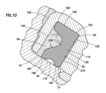
fill with earthen cuttings and try to cause them to pack. But, as can be seen
in Figures 9 and 10,
the groove 30 on the grease side 110 of the seal 50 provides space for the
seal 50 to move into as
it gets packed with cuttings 64 on the mud side The space on the grease side
110 may be
smaller than space on the mud side .111 of the seal 50.
In operation under downhole pressure as shown in Figure 9, the hydrostatic
pressure of
the environment causes the outside diameter 156 about air gap 115 to make full
contact with a
base 125 at the bottom of the seal groove 30 opposite the seal land 44. When
maintained against
the seal land 44, the mud lobe 150 may provide a barrier to prevent passage
(or intrusion) of
fluids and/or cuttings (or other abrasive particles). As also shown in Fig 9,
when the seal 50 is in
the seal groove 30 and is operated at the very high hydrostatic pressures
often seen in downhole
drilling, the seal 50 assumes a 'wrinkled' appearance caused by a small amount
of rubber
deflection, and a small amount of buckling caused by increased stiffness due
to the compression
of the seal 50. A grease side wall (or grease wall) 135 on the 'grease' side
110 may be close to
and substantially parallel to the grease side 110 so that any small inward
pressure on the seal 50
due to cutting encroachment may be resisted by the contact between the grease
side 110 and the
grease wall 135.
The asymmetric shape of the seal 50 may cause it to have a non-uniform, biased
load
upon it. A central area of the seal 50 is arranged to provide more load in the
inner lip (or grease
lobe) 140 than the outer lip (or mud lobe) 150. This biased load may enhance
the sealing ability
of the inner lip 140 while reducing the wear on the outer exclusion lip 150 by
reducing its
contact force. The shape of the mud cavity 200 above the outer lip 150 will be
'energized' by
the packing of the cuttings to better prevent intrusion of cuttings under the
outer lip 150 as
shown in Figure 10. In a similar manner, the same effect will act on the
outside diameter of the
mud side 'ear' 160.
The seal 50 may be comprised of a variety of materials, e.g., an elastomeric
material that,
in one embodiment, may have a Shore A hardness ranging from approximately 60-
90 durometer,
However, it is also within the scope of this disclosure to make the seal 50
from fluorocarbon or
any other suitable resilient sealing material.
Therefore, disclosed herein is a sealed and lubricated rolling cutter earth
boring drill bit
100 comprising a seal 50, wherein the seal 50, upon installation, comprises
one or more air gaps
(e.g., mud cavity 200, grease cavity 210, air gap 115 and/or lubrication
groove 116) at
9
CA 02827207 2015-02-13
55235-8
atmospheric pressure which, when exposed to a high pressure drilling
environment, closes the
trapped void space around the outside diameter 156 of the seal 50.
Referring now to Figures 11A-11C, the seal 50 is shown in greater detail. As
shown in these figures, the seal 50 has an asymmetric configuration along its
longitudinal
cross-section (about longitudinal axis Y). Figure 11A shows a plan view of the
seal 50. Figure
11B shows a cross-sectional view of the seal 50 of 11A taken along line 11B-
11B. Figure 11C
is a detailed view of section 11C of the seal 50 of Figure 11B. Example
dimensions for the
seal 50 are shown in Figure 11C.
The dimensions of the seal 50 may be adjusted to provide desired sealing
capabilities. For example, a horizontal width W3 of the seal at a base end, a
horizontal width
W2 at a land end, and a horizontal width W1 at an intermediary position may be
defined.
Vertical lengths L1 of the mud cavity 200, L2 of the grease cavity 210 and L3
of the seal 50
may also be defined. Other dimensions, such as mud cavity angle a2 and grease
cavity al may
also be defined. A depth G3 of air gap 115 and depth G4 of lubrication groove
116 may also be
defined. By way of example, the seal 50 may have a width W2 of about 6.3 mm,
W1 of about
3.15 mm, and W3 of about 8 mm; length L1 of about 7.54 mm, L2 of about 7.09
mm, and L3 of
about 12.67 mm; angle al and a2 of about 45 degrees; and gaps G1 and G2 of
about
0.76 mm, G3 of about 0.64 mm, and G4 of about 0.86 mm.
The width W3 of the seal 50 at the mud ear 160 and grease ear 130 may be
greater than a width of the seal groove 30 to prevent passage of fluid and/or
particles into the
air gap 115. The width W1 along a central portion of the seal 50 may be from
about 40 to
about 50 percent of the width W2. The widths W1 and W2 may be selected to
define the
desired contact force of the seal 50 during operation. The lengths Li and L2
of the cavities 200
and 210 may be substantially the same and may be from about 55 to about 80
percent of the
length L3 of the seal. The inside diameter 158 and outside diameter 156 may be
centered along
axis Y to provide gaps G1 and G2 for freedom of movement along the inside
diameter 158
(gaps G1 and G2 are shown in Figure 8). Gaps G1 and G2 may be from about 10 to
about 20
percent of the width W2, and gap GI may be about the same as gap G2.
CA 02827207 2015-02-13
55235-8
As shown in Figure 11C, the mud side 111 and grease side 110 volumes depicted
as
cross-sectional areas A1, A2 defined by cavities 200, 210 formed on the sides
111, 110 of the seal 50 of
the present disclosure are illustrated period. In addition, the relationship
of the mud side 'overhang' 175
and the grease side 'overhang' 170 of seal lobes 140, 150 may be described as
a ratio A1/A2. In order
to provide the benefits as described above, the shape and design of the lobes
may be adjusted such that
the ratio of the areas A1/A2 is greater than or equal to about 2.5. In some
cases, the ratio may be
greater than or equal to about 2.766.
Figures 12A-12C depict an alternate seal 350 having an asymmetric
configuration
along its longitudinal cross-section (about longitudinal axis Z). Figure 12A
shows a plan view of the
seal 350. Figure 12B shows a cross-sectional view of the seal 350 of 12A taken
along line 12B-12B.
Figure 12C is a detailed view of section 12C of the seal 350 of Figure 12B.
Example dimensions for
the seal 350 are shown in Figure 12C. In this version, the seal 350 is
provided with a spring 352
extending into a grease side 310 adjacent cavity 320 for reinforcement during
operation.
The seal 350 has a mud lobe 351, a grease lobe 340, a mud ear 360, a grease
ear 330,
an air gap 315, a lubrication groove 316, a mud side 311, a grease side 310,
an inside diameter 358 and
an outside diameter 356. The mud side 311 may have a cavity 300 having an area
B1 and the grease
side 310 may have a grease cavity 320 having an area B2. The areas B1 and B2
(excluding the spring
pocket 357 and spring 352) may be substantially the same. The mud ear 360 and
the grease ear 330
may be symmetric about the axis Z.
The dimensions of the seal 350 may be adjusted to provide desired sealing
capabilities. For example, a horizontal width W6 of the seal at a base end, a
horizontal width W4 at a
land end, and a horizontal width W5 at an intermediary position may be
defined. Vertical lengths L4 of
the mud cavity 300, L5 of the grease cavity 210 and L6 of the seal 350 may
also be defined. Other
dimensions, such as depth G5 of air gap 315 and a depth G6 of lubrication
groove 316 may also be
defined. By way of example, the seal 350 may have a width W4 of about 6.3 mm,
W5 of about
3.15 mm, and W6 of about 8 mm; length L4 of about 7.34 mm, L5 of about 7.21
mm, L6 of about
12.45 mm, and L9 of about 3.15 mm; and gaps G5 of about 0.64 mm, and G6 of
about 0.86 mm.
As shown in Figure 12C, the mud side and grease side volumes depicted as cross-
sectional areas B1, B2 defined by cavities 300, 320 formed on the sides 311,
310 of the seal 350 of the
present disclosure are illustrated. The spring 352 may be, for example, a
garter spring. The spring 352
11
CA 02827207 2015-02-13
55235-8
may extend into a spring pocket 357 positioned between the vertical centerline
Z of the seal 350 and
the grease lobe 340. The spring 352 may be used to help energize the seal
during operation.
The spring pocket 357 may have a generally round shape extending through the
grease
side 310 of the seal 350. A shoulder 333 (or spring retainer) along the grease
side 310 may be
positioned about an opening 334 to the spring pocket 357. The garter spring
352 may be positioned,
under tension, in the spring pocket 357. The garter spring 352 may reinforce
the seal 350 to maintain a
sealing contact force thereof. The sealing contact force may be the force
applied to the bearing spindle
16 and the cutter drill bit 18 by the seal 350. To provide a cantilever to the
seal 350 for supporting the
seal in sealing contact, the garter spring 352 may be positioned below a
horizontal midpoint of the seal
350 and to the right of centerline Z. The position of the garter spring 352 in
the seal 350 may be used
to direct most of the sealing contact force towards the inside diameter of the
seal 350.
In this version an area B1 of the mud cavity 300 is about the same size and
shape as
the area B2 of the grease cavity 310. Also, the spring pocket 357 has a radius
R corresponding with the
outer diameter D of the spring 352. A center of the spring 352 in position
within the spring pocket 357
is positioned at a length L8 from the land end and a length L7 from a
centerline of the seal 350. A
length L9 may be defined from the centerline Z to a grease side of the grease
lobe 350, and a length
L 10 may be defined from the centerline Z to a mud side of the mud lobe 351. A
thickness T may be
defined between the spring pocket 357 and the mud cavity 300. The spring 352
sits below a horizontal
centerline of the seal 350. By way of example, the seal 350 may have a radius
R of about 1.27 mm;
and a length L8 of about 3.94 mm and L7 of about 2.29 mm. The length L8 may be
from about 20 to
about 40 percent of L6, and L7 may be from about 50 to about 90 percent of L9.
The thickness T may
be substantially less than the width W5 (e.g., about 50 percent).
Figure 13A depicts a prior art seal 305 with a textured surface 307 on the
inside
diameter. Figure 13B depicts a detailed view of the textured surface 307. The
pattern of the textured
surface 307 includes pockets 309 with jagged edges 308 that may trap lubricant
reducing friction and
heat generation. A central rib 319 extends along a central line of the inner
diameter 321 with mirrored,
non-directional patterns 317 on each side thereof. Configurations for seals
and textures that may be
used are provided in US Patent No. 4,619,534, the entire contents of which are
hereby incorporated by
reference.
Figures 14A and 14B depict an alternate seal 450 usable with the drill bits
described
12
CA 02827207 2013-08-13
WO 2012/112333 PCT/US2012/024042
herein. The seal 450 may be similar to the seal 350 previously described,
except. that no spring
pocket, spring or lubrication groove is provided. in this version as shown,
the seal 450 has
symmetric configuration about a longitudinal axis V. and a textured surface
452 along an inside
diameter 458. The seal 450 may also have a. cross-section similar to the other
seals provided
herein.
The textured surface 452 may be provided to facilitate sealing of the seal 450
to the seal
land 44 along the. inside diameter 458. Figure 1413 depicts another textured
surface 452 that may
be used to facilitate expulsion of abrasive particles during operation. The
textured surfa.ce 452
has a central rib 460 along a central line of the inside diameter 458 to
maintain a positive seal
against the seal land. A grease side of the textured surface 452 has a non-
directional pattern
462a. .A mud side of the textured surface 452 has a directional. pattern 462b
with a side lip 464
on a mud side thereof. .The side lip 464 is positioned along the mud side to
deflect abrasive
particles to prevent movement of such particles to the grease side of the
seal. The mud side
textured pattern 462b has ribs 470 tbr trapping lubricant and for sealing
engagement with the
seal land 44. The ribs 470 may be provided at an angle to facilitate expulsion
a abrasive
particles. The angle of the textured ribs 470 may be, fbr example, about 45
degrees from the
longitudinal axis V. Should the side lip 464 wear away, the texttirized ribs
470 may be
positioned at an angle to expel particles.
The seals 50;350 and 450 may have a body made up of, for example, a high
temperature
elastomer, such as 'fluorocarbon (FKM) (e.g., VITONTm); perfluoroelastomer
(FFKM) (e.g.,
[CAME:Pm); or tetrafluoroethylene propylene (IFEPM) (e.g., AFLASTm).
The dimensions of the seals 50, 350 and 450 may be configured to allow the
seal 350 to
deform as shown in Figures 9 and 10. Various features of the seals may be
interchangeable. For
example, the spring of seal 350 may be used in seal 50 and/or the asymmetric
cross-section of
seal 50 may be used in. the seal 350. As shown, the seals 50 and 350 have
asymmetric,
longitudinal configurations that provide additional support on (or force to)
the grease side of the
seal.
In some eases, the seals may be configured to accept high pressures (e.g.,
hydrostatic
and/or cuttings) and deform such that the mud lobe and grease lobe remain in
contact with seal
land 44. The air gap may be reduced and/or eliminated as the seal is pressed
against the grease
wall under downhole pressure. Such configurations may also be used to prevent
:lifting of the ear
13
CA 02827207 2015-02-13
' 5525-8
. and/or lobe that may occur in some configurations as .shown, for example, in
Figure 5.
In operation, the .seals..50, 350 and 450 may be positioned in the drill bit
10 or 100 with
pressure applied thereto by hydroStatic-ptessure.andlor cuttings. tinder even
extreme pressures
-(e.g., more than about 1000 kg/cm), the seals may maintain a mud lobe and
grease lobe thereof
against a landing thereby maintaining a seal between the beating spindle 1.6
and the rolling cutter
18.
Whereas the present disclosure has been described in particular relation to
the drawings
attached hereto, it should be understood that other and further modifications
apart from those.
shown or suggested herein, may be made within the scope of the present
disclosure.
14
=