Note: Descriptions are shown in the official language in which they were submitted.
CA 02827553 2015-11-09
P15085CA00
SN 2,827,553
- 1 -
TWIN CLUTCH CONTROLLING APPARATUS
FIELD OF THE INVENTION
The present invention relates to a twin clutch controlling apparatus, and
particularly to a twin clutch controlling apparatus which applies automatic
control
and manual operation of a clutch in a complex manner.
BACKGROUND OF THE INVENTION
In the past, in a clutch controlling apparatus which controls a clutch of a
transmission incorporated in a power source of a vehicle between a connection
state and a disconnection state by an actuator, a configuration which includes
manual operation means such as a clutch lever to allow application of both of
automatic control and manual operation of the clutch is known.
Japanese Patent Laid-Open No. 2011-112094 discloses a configuration of a
transmission of the constant mesh type for a motorcycle which includes a twin
clutch configured from a first clutch which takes charge of odd number stage
side
gears and a second clutch which takes charge of even number stage side gears.
According to the configuration, the twin clutch is automatically controlled by
an
actuator, while an interposition of a manual operation according to an
operation of
a clutch lever is permitted.
In the technology disclosed in Japanese Patent Laid-Open No. 2011-112094, an
automatic control mode and a manual control mode are provided as control modes
for the clutch. However, there still is room for consideration in regard to in
what
manner the operation amount of the clutch lever is reflected particularly on
the
clutch capacity when the manual control mode is selected.
CA 02827553 2013-09-18
- 2 -
SUMMARY OF THE INVENTION
The object of the present invention resides in provision of a twin clutch
controlling apparatus which can solve the problem of the related art described
above
and wherein an interposition of a manual operation into an automatic control
clutch
can be carried out smoothly.
According to one aspect of the present invention, a twin clutch controlling
apparatus which includes a multi-speed transmission having a plurality of gear
trains between a main shaft on the input side and a countershaft on the output
side,
a shift actuator for carrying out changeover of a shift stage of the multi-
speed
transmission, a twin clutch configured from an odd number stage side clutch
and an
even number stage side clutch for connecting and disconnecting power
transmission
between the transmission and an engine, a clutch actuator for controlling the
twin
clutch, and an manual operation clutch capacity arithmetic operation section
for
converting an operation amount of a clutch manual operation means to
arithmetically operate a manual operation clutch capacity arithmetic operation
value
corresponding to the manual operation, has a first characteristic in that it
includes a
control section for controlling the shift actuator and the clutch actuator,
and shift
manual operation means for carrying out a shifting request to the control
section, the
control section being configured such that, if, after driving of the shift
actuator is
started in response to the shifting request by the shift manual operation
means, the
clutch manual operation means is operated in a connection direction before a
next
stage gear is placed into an in-gear state, then one of the odd number stage
side
clutch and the even number stage side clutch which corresponds to the gear
before
the shifting is driven in a corresponding relationship to the manual operation
clutch
capacity arithmetic operation value.
According to the above aspect of the invention, the twin clutch controlling
apparatus includes a control section for controlling the shift actuator and
the clutch
actuator, and a shift manual operation means for carrying out a shifting
request to
the control section. Further, the control section is configured such that, if,
after
driving of the shift actuator is started in response to the shifting request
by the shift
manual operation means, the clutch manual operation means is operated in a
connection direction before a next stage gear is placed into an in-gear state,
then one
of the odd number stage side clutch and the even number stage side clutch
which
WH-P15085CA00/1h
CA 02827553 2013-09-18
- 3 -
corresponds to the gear before the shifting is driven in a corresponding
relationship
to the manual operation dutch capacity. Therefore, while escape of the driving
force
which occurs when the clutch on the side corresponding to the next stage gear
is
connected before the next stage gear is placed into an in-gear state is
prevented,
switching of the dutch can be executed smoothly to connect the dutch.
Consequently, it is possible to enhance the direct sense of a shift change
operation
and enhance the drivability.
In another aspect of the invention, the action of driving that has one of the
odd
number stage side clutch and the even number stage side clutch which
corresponds
to the gear before the shifting corresponded to the manual operation dutch
capacity
arithmetic operation value is executed when the shifting request by the shift
manual
operation means is carried out after the clutch manual operation means is
operated
in a disconnection direction and the operation amount of the clutch manual
operation means reaches a predetermined value.
According to the above aspect of the invention, the action of driving that has
one of the odd number stage side clutch and the even number stage side clutch
which corresponds to the gear before the shifting corresponded to the manual
operation clutch capacity is executed when the shifting request by the shift
manual
operation means is carried out after the clutch manual operation means is
operated
in a disconnection direction and the operation amount of the clutch manual
operation means reaches a predetermined value. Therefore, for example, when
the
shifting request by the shift manual operation means is executed before the
clutch
manual operation means is operated in the disconnection state and this
operation
amount reaches the predetermined value, at a point of time at which the shift
manual operation means is operated in the disconnection state and the
operation
amount reaches the predetermined value, the clutch can be changed
corresponding
to the manual operation dutch capacity. However, by suspending the change of
the
clutch corresponding to the manual operation clutch capacity to leave the
possibility
of a connection action of the dutch corresponding to the gear before the
shifting,
occurrence of escape of the driving force can be prevented.
In a further aspect of the invention, an auto mode in which the twin clutch is
automatically controlled by the control section, a manual mode in which the
twin
clutch is manually controlled in response to the manual operation clutch
capacity
arithmetic operation value, and a temporary manual mode are provided for a
control
WH-P15085CA00/1h
CA 02827553 2013-09-18
- 4 -
mode for the twin clutch, an automatic shift mode and a manual shift mode are
provided for a control mode for the multi-speed transmission, and where the
control
mode of the twin clutch is set to the manual mode, the control mode of the
multi-
speed transmission becomes the manual shift mode.
According to the above aspect of the invention, a control mode for the twin
dutch includes an auto mode in which the twin clutch is automatically
controlled by
the control section, a manual mode in which the twin clutch is manually
controlled
in response to the manual operation clutch capacity, and a temporary manual
mode,
and a control mode for the multi-speed transmission includes an automatic
shift
mode and a manual shift mode. Further, where the control mode of the twin
clutch
is set to the manual mode, the control mode of the multi-speed transmission
becomes the manual shift mode. Therefore, by executing the three control modes
of
the twin dutch and two control modes of the multi-speed transmission
cooperatively, a manual operation by the dutch manual operation means such as
a
clutch lever and the shift manual operation means such as a shift pedal can be
interposed into the automatic shift control without a sense of discomfort.
In yet another aspect of the invention, the control section drives, when,
while
the manual mode is selected, the clutch manual operation means is operated in
a
traveling state of a motorcycle in which the engine is incorporated, the
clutch, which
currently is in a connected state, in response to the manual operation clutch
capacity
arithmetic operation value, to the disconnection side, and then drives, when,
after a
shift up request is issued from the shift manual operation means, the clutch
manual
operation means is driven to the connection side before a next stage gear is
placed
into an in-gear state, one of the odd number stage side clutch and the even
number
stage side clutch which corresponds to the gear before the shifting in a
corresponding relationship to the manual operation clutch capacity arithmetic
operation value and then starts a switching action of the clutch using it as a
trigger
that establishment of the in-gear stage of the next stage gear is completed.
According to the above aspect of the invention, the control section drives,
when,
while the manual mode is selected, the dutch manual operation means is
operated in
a traveling state of a motorcycle in which the engine is incorporated, the
clutch,
which currently is in a connected state, in response to the manual operation
dutch
capacity, to the disconnection side, and then drives, when, after a shift up
request is
issued from the shift manual operation means, the dutch manual operation means
is
WH-P15085CA00/1h
CA 02827553 2013-09-18
- 5 -
driven to the connection side before a next stage gear is placed into an in-
gear state,
one of the odd number stage side clutch and the even number stage side clutch
which corresponds to the gear before the shifting in a corresponding
relationship to
the manual operation clutch capacity and then starts a switching action of the
clutch
using it as a trigger that establishment of the in-gear stage of the next
stage gear is
completed. Therefore, while escape of the driving force which occurs when the
clutch on the side corresponding to the next stage gear is connected before
the next
stage gear is placed into an in-gear state is prevented, switching of the
clutch can be
executed smoothly using completion of placement of the next stage gear into an
in-
gear state based on a parameter which can be detected by a sensor.
In yet a further aspect of the twin dutch controlling apparatus, using it as a
trigger that, after starting of the switching action of the clutch, the manual
operation
dutch capacity arithmetic operation value becomes coincident with a clutch
capacity
of the clutch on the side corresponding to the next stage gear, the manual
operation
clutch capacity arithmetic operation value is made correspond to a clutch
capacity of
the dutch on the side corresponding to the next stage gear.
According to the above aspect of the invention, using it as a trigger that,
after
starting of the switching action of the dutch, the manual operation clutch
capacity
becomes coincident with a clutch capacity of the clutch on the side
corresponding to
the next stage gear, the manual operation clutch capacity is made correspond
to a
clutch capacity of the clutch on the side corresponding to the next stage
gear.
Therefore, the driving method of the clutch on the side corresponding to the
next
stage gear can be changed over based on a definite parameter that the manual
operation clutch capacity and the clutch capacitor of the clutch on the side
corresponding to the next stage gear coincide with each other.
BRIEF DESCRIPTION OF THE DRAWINGS
Preferred embodiments of the invention are shown in the drawings, wherein:
FIG. 1 is a left side elevational view of a motorcycle to which a transmission
control apparatus for a twin clutch type automatic transmission according to
an
embodiment of the present invention is applied.
WH-P15085CA00/1h
CA 02827553 2013-09-18
- 6 -
FIG. 2 is a right side elevational view of an engine as a power source of the
motorcycle.
FIG. 3 is a system diagram of an AMT and peripheral apparatus.
FIG. 4 is an enlarged sectional view of the transmission.
FIG. 5 is an enlarged sectional view of a transmission mechanism.
FIG. 6 is a developed view showing a shape of guide grooves of a shift drum.
FIG. 7 is a table of shift positions defined by the shift drum.
FIG. 8 is a graph illustrating a relationship between the operation amount of
a
clutch lever and an output signal of a clutch operation amount sensor.
FIG. 9 is a block diagram showing a configuration of an AMT controlling unit.
FIG. 10 is a block diagram illustrating an arithmetic operation procedure of a
shift motor driving output value and a clutch capacity output value.
FIG. 11 is a state transition diagram illustrating a relationship among three
clutch
control modes.
FIG. 12 is a flow chart illustrating a procedure for deciding a clutch for
which a
manual operation is to be executed.
FIG. 13 is a flow chart illustrating a procedure for deciding an Auto mode
connection side clutch.
FIG. 14 is a flow chart (1/2) illustrating a procedure of a clutch capacity
output
value arithmetic operation.
FIG. 15 is a flow chart (2/2) illustrating the procedure of the clutch
capacity
output value arithmetic operation.
WH-P15085CA00/1h
CA 02827553 2013-09-18
- 7 -
FIG. 16 is a time chart illustrating a flow upon shifting to the fourth speed
during traveling by the third speed.
DETAILED DESCRIPTION OF THE PREFERRED EMBODIMENTS
In the following, a preferred embodiment of the present invention is described
in detail with reference to the drawings. FIG. 1 is a left side elevational
view of a
motorcycle 10 to which a transmission controlling apparatus for a twin clutch
type
automatic transmission according to an embodiment of the present invention is
applied. FIG. 2 is a right side elevational view of an engine 100 as a power
source of
the motorcycle 10. A vehicle body frame 14 of the motorcycle 10 has a pair of
left
and right main pipes 36, and a head pipe 15 is provided on the vehicle body
front
side of the main pipes 36. A pair of left and right front forks 17 support a
front
wheel WF for rotation thereon and support a steering handlebar 18. The front
forks
17 are supported for pivotal motion with respect to the head pipe 15.
The engine 100 is suspended below the main pipes 36 and is a V-type four-
cylinder engine wherein front and rear cylinders are disposed with a
predetermined
nip angle formed therebetween. A piston 41, a valve mechanism and so forth
which
slidably move in a cylinder block 40 have a similar configuration among the
four
cylinders. A crankshaft 105, a main shaft 13 and a countershaft 9 are
accommodated
in a crankcase 46. The crankshaft 105 supports connecting rods 41a (refer to
FIG. 2),
on each of which a piston 41 is supported, for rotation thereon. The main
shaft 13
and the countershaft 9 have a plurality of gear pairs, which configure a
transmission,
attached thereto.
Between the front and rear cylinder blocks, air funnels 42 are disposed. The
air
funnels 42 introduce fresh air having passed through an air cleaner box
disposed at a
lower portion of a fuel tank 19 to intake ports of the cylinders. Each air
funnel 42 has
a fuel injection valve attached thereto. A muffler 54 is disposed below a seat
53 and
exhausts combustion gas introduced to the rear side of the vehicle body by an
exhaust pipe 59.
A swing arm 38 is supported for rocking motion at a rear lower portion of the
main pipes 36. The swing arm 38 is suspended by shock units 37 and supports a
rear
WH-P15085CA00/1h
CA 02827553 2013-09-18
- 8 -
wheel WR for rotation thereon. A drive shaft 58 is disposed inside the swing
arms
38 and transmits rotational driving force of the engine 100 outputted from the
countershaft 9 to the rear wheel WR. A vehicle speed sensor SEV is provided in
the
proximity of an axle of the rear wheel WR and detects a rotational speed of
the rear
wheel WR.
A clutch lever L is attached to the left side of the steering handlebar 18 in
the
vehicle widthwise direction and servers as clutch manual operation means for
connecting and disconnecting transmission of driving force between the engine
100
and the rear wheel WR. A shift pedal P is attached in the proximity of a foot
placing
step on the left side in the vehicle widthwise direction and serves as shift
manual
operation means for carrying out a shift change of a transmission TM.
Referring to FIG. 2, each of a front bank Bf and a rear bank BR which
configure
the engine 100 is configured from a cylinder head 44 attached to the upper
side of a
cylinder block 40 and accommodating a valve mechanism therein and a head cover
45 which covers an upper end of the cylinder head 44. A piston 41 slidably
moves
along an inner circumference of a cylinder 43 formed in the cylinder blocks
40. The
crankcase 46 is configured from an upper case half 46a formed integrally with
the
cylinder blocks 40 and a lower case half 46b to which an oil pan 47 is
attached.
A water pump 49 for pressure feeding cooling water is driven to rotate by an
endless chain 48 wrapped around a sprocket wheel 13a formed on the main shaft
13.
A clutch cover 50 is attached to a side face on the right side of the
crankcase 46 in the
vehicle widthwise direction.
The engine 100 in the present embodiment applies, as a hydraulic clutch for
connection and disconnection of rotational driving force to and from the
transmission, a clutch of the twin clutch type configured from a first clutch
and a
second clutch. The hydraulic pressure to be supplied to the twin clutch can be
controlled by an actuator, and a first valve 107a and a second valve 107b as
actuators
controlling the two clutches are attached to a right side portion of the
engine 100.
The twin clutch TCL is driven to connect and disconnect by a combination of
automatic control in response to the engine speed, vehicle speed and so forth
and a
driving instruction of an occupant by an operation of the clutch lever L.
WH-P15085CA00/1h
CA 02827553 2013-09-18
- 9 -
FIG. 3 is a system diagram of an automatic manual transmission (hereinafter
referred to as AMT) 1 as an automatic transmission and peripheral apparatus of
the
AMT 1. The AMT 1 is a twin clutch type automatic transmission apparatus which
connects and disconnects the rotational driving force of the engine by the two
clutches disposed on the main shaft. The AMT 1 accommodated in the crankcase
46
is controlled and driven by a clutch hydraulic system 110 and an AMT
controlling
unit 120. The AMT controlling unit 120 includes clutch controlling means for
controlling driving of the valve 107 as a clutch actuator configured from the
first
valve 107a and the second valve 107b. Further, the engine 100 includes a
throttle
body 102 of the throttle-by-wire type in which a throttle valve motor 104 for
opening
and closing the throttle valve is provided.
The AMT 1 includes a transmission TM of forward six stages, a twin clutch TCL
configured from a first clutch CL1 and a second clutch CL2, a shift drum 30,
and a
shift motor (shift actuator) 21 for rotating the shift drum 30. The shift
motor 21 is
driven to rotate by a combination of automatic control in response to an
engine
speed, a vehicle speed and so forth and a driving instruction of an occupant
by an
operation of the shift pedal P.
A large number of gears which configure the transmission TM are coupled to or
loosely fitted on the main shaft 13 or the countershaft 9. The main shaft 13
is
configured from an inner main shaft 7 and an outer main shaft 6, and the irmer
main
shaft 7 is coupled to the first clutch CL1 while the outer main shaft 6 is
coupled to the
second clutch CL2. Transmission gears are provided on the main shaft 13 and
the
countershaft 9 such that they are displaceable in the axial direction of the
main shaft
13 and the countershaft 9. Shift forks 71, 72, 81 and 82 are engaged at end
portions
thereof with the transmission gears and a plurality of guide grooves formed on
the
shift drum 30.
A primary driving gear 106 is coupled to the crankshaft 105 of the engine 100
and is held in mesh with a driven gear 3. The primary driven gear 3 is
connected to
the inner main shaft 7 through the first clutch CL1 and connected to the outer
main
shaft 6 through the second clutch CL2. Further, the AMT 1 includes an inner
main
shaft rotational speed sensor 131 and an outer main shaft rotational speed
sensor 132
which measure the rotational speed of predetermined transmission gears on the
countershaft 9 to detect the rotational speed of the inner main shaft 7 and
the outer
main shaft 6, respectively.
WH-P15085CA00/1h
CA 02827553 2013-09-18
- 10 -
The inner main shaft rotational speed sensor 131 detects the rotational speed
of
a driven side transmission gear C3 which is attached for rotation but against
sliding
movement on the countershaft 9 and is held in meshing engagement with a
transmission gear attached against rotation on the inner main shaft 7.
Meanwhile,
the outer main shaft rotational speed sensor 132 detects the rotational speed
of a
driven side transmission gear C4 which is attached for rotation but against
sliding
moment on the countershaft 9 and is held in meshing engagement with a
transmission gear attached against rotation to the outer main shaft 6.
A bevel gear 56 is coupled to an end portion of the countershaft 9. The bevel
gear 56 meshes with another bevel gear 57 coupled to the drive shaft 58 to
transmit
the rotational driving force of the countershaft 9 to the rear wheel WR.
Further, in
the AMT 1, an engine speed sensor 130, a gear position sensor 134, a shifter
sensor
27, and a neutral switch 133 are provided. The engine speed sensor 130 is
disposed
in an opposing relationship to an outer periphery of the primary driven gear
3. The
gear position sensor 134 detects a gear stage position of the transmission TM
based
on the rotational position of the shift drum 30. The shifter sensor 27 detects
a
pivoted position of a shifter which is driven by the shift motor 21. The
neutral
switch 133 detects that the shift drum 30 is at a neutral position. A throttle
opening
sensor 103 is provided on the throttle body 102 and detects a throttle
opening.
The clutch hydraulic system 110 is configured such that it uses both of
lubricating oil for the engine 100 and hydraulic oil for driving the twin
clutch. The
clutch hydraulic system 110 includes an oil tank 114, and a pipe line 108 for
feeding
oil (hydraulic oil) in the oil tank 114 to the first clutch CL1 and the second
clutch
CL2. On the pipe line 108, a hydraulic pump 109 as a hydraulic supply source
and a
valve (electromagnetic control valve) 107 as a clutch actuator are provided.
On a
return pipe line 112 connected to the pipe line 108, a regulator 111 for
normally
keeping the hydraulic pressure to be supplied to the valve 107 to a fixed
value is
disposed. The valve 107 is configured from the first valve 107a and the second
valve
107b which can supply pressure oil to the first clutch CL1 and the second
clutch CL2,
respectively. An oil return pipe line 113 is provided for each of the first
valve 107a
and the second valve 107b.
A first hydraulic pressure sensor 63 is provided on a pipe line which connects
the first valve 107a and the first clutch CL1 to each other and measures the
hydraulic
WH-P15085CA00/1h
CA 02827553 2013-09-18
- 11 -
pressure generated in the pipe line, namely, the hydraulic pressure generated
in the
first clutch CL1. Similarly, a second hydraulic pressure sensor 64 is provided
on
another pipe line which connects the second valve 107b and the second clutch
CL2 to
each other and measures the hydraulic pressure generated in the second clutch
CL2.
Further, on the pipe line 108 which connects the hydraulic pump 109 and the
valve
107 to each other, a main hydraulic pressure sensor 65 and a third hydraulic
pressure
sensor 66 as oil temperature detection means are provided.
To the AMT controlling unit 120, a shift mode changeover switch 116, a shift
switch 115, a neutral select switch 117 and a clutch control mode changeover
switch
118 are connected. The shift mode changeover switch 116 carries out changeover
between an automatic shift (AT) mode and a manual shift (MT) mode of the
transmission TM. The shift switch 115 serves as shift manual operation means
which
carries out shift instruction for shift up (UP) or shift down (DN). The
neutral select
switch 117 carries out changeover between the neutral (N) position and the
drive (D)
position. The clutch control mode changeover switch 118 carries out changeover
of a
control mode for clutch operation. The clutch control mode changeover switch
118 is
a push type switch which exhibits an on state from an off state only when it
is
pushed. The clutch control mode changeover switch 118 can arbitrarily carry
out
changeover between an Auto mode in which clutch control is carried out
automatically and a Manual mode in which the clutch is driven in response to
an
operation of the clutch lever L, under a predetermined condition. The switches
are
provided on handlebar switches of the steering handlebar 18.
It is to be noted that the shift pedal P does not have a mechanical connection
to
the shift drum 30 but functions as a switch which sends a shifting request
signal to
the AMT controlling unit 120 similarly to the shift switch 115. Further, the
clutch
lever L does not have a mechanical connection to the twin clutch but functions
as a
switch which sends a dutch operation request signal to the AMT controlling
unit
120.
The AMT controlling unit 120 includes a central processing unit (CPU) and
controls the valve (clutch actuator) 107 and the shift motor (shift actuator)
21 in
response to output signals of the sensors and the switches described above to
change
the shift position of the AMT 1 automatically or semi-automatically. Upon
selection
of the AT mode, the shift position is changed over automatically in response
to
information of the vehicle speed, engine speed, throttle opening and so forth.
In
WH-P15085CA00/1h
CA 02827553 2013-09-18
- 12 -
contrast, upon selection of the MT mode, the transmission TM is shifted up or
down
in response to an operation of the shift switch 115 or the shift pedal P. It
is to be
noted that, also upon selection of the MT mode, auxiliary automatic shift
control for
preventing an overspeed, installation and so forth of the engine can be
executed.
In the clutch hydraulic system 110, a hydraulic pressure is applied to the
valve
107 by the hydraulic pump 109 and is controlled by the regulator 111 so that
it does
not exceed an upper limit value. If the valve 107 is opened in accordance with
an
instruction from the AMT controlling unit 120, then the hydraulic pressure is
applied
to the first clutch CL1 or the second dutch CL2 to connect the primary driven
gear 3
to the inner main shaft 7 or the outer main shaft 6 through the first dutch
CL1 or the
second clutch CL2. In particular, both of the first clutch CL1 and the second
clutch
CL2 are normally open type hydraulic dutches. If the valve 107 is closed to
stop the
application of the hydraulic pressure, then the first dutch CL1 or the second
clutch
CL2 is urged in a direction in which the connection between the inner main
shaft 7
and the outer main shaft 6 is cut by a return spring (not shown) built
therein.
The valve 107 which opens and closes the pipe lines which connect the pipe
line
108 and the two clutches to each other to drive the clutches is configured
such that
the AMT controlling unit 120 adjusts the driving signal so that the time and
so forth
required to place the pipe lines from a fully closed state to a fully open
state can be
changed arbitrarily.
The shift motor 21 rotates the shift drum 30 in accordance with an instruction
from the AMT controlling unit 120. When the shift drum 30 rotates, the shift
forks
71, 72, 81 and 82 are displaced in an axial direction of the shift drum 30 in
accordance
with the shape of guide grooves formed on the outer periphery of the shift
drum 30,
whereupon the meshing relationship between the gears on the countershaft 9 and
the main shaft 13 changes.
The AMT 1 according to the present embodiment is configured such that the
inner main shaft 7 coupled to the first dutch CL1 supports odd number stage
side
gears (first, third and fifth stages) and the outer main shaft 6 coupled to
the second
clutch CL2 supports even number stage side gears (second, fourth and sixth
stages).
Accordingly, for example, while the motorcycle runs with an odd number stage
side
gear, supply of the pressure oil to the first dutch CL1 continues and the
connection
state is maintained. Then, upon shift change, the transmission gear which
transmits
VVH-F15085CA00/1h
CA 02827553 2013-09-18
- 13 -
driving force is changed over by carrying out a clutch switching operation in
a state
in which the transmission gears before and after the shift change remain in a
meshing state.
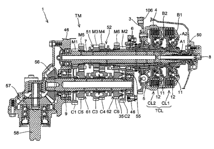
FIG. 4 is an enlarged sectional view of the transmission TM. Like reference
characters to those used in the foregoing description denote like or
equivalent
portions. Rotational driving force is transmitted from the crankshaft 105 of
the
engine 100 to the primary driven gear 3 having a shock absorption mechanism 5
thereon through the primary driving gear 106. Then, the rotational driving
force is
transmitted from the twin clutch TCL to the countershaft 9 to which the bevel
gear
56 is attached through the outer main shaft 6 and the inner main shaft 7
supported
for rotation in the outer main shaft 6 and further through the six gear pairs
provided
between the main shaft 13 (outer main shaft 6 and inner main shaft 7) and the
countershaft 9. The rotational driving force transmitted to the bevel gear 56
is
transmitted to the drive shaft 58 with the rotational direction thereof is
changed to
the vehicle body rear side by the bevel gear 57 with which the bevel gear 56
meshes.
The transmission TM has six transmission gear pairs between the main shaft and
the countershaft and can select which gear pair should be used to output the
rotational driving force depending upon a combination of the position of a
slidably
movable gear attached for sliding movement in an axial direction of each shaft
and
the connection or disconnection state of the first clutch CL1 and the second
clutch
CL2. The twin clutch TCL is disposed in the inside of a clutch case 4 which
rotates
integrally with the primary driven gear 3. The first dutch CL1 is attached
against
rotation on the inner main shaft 7 while the second clutch CL2 is attached
against
rotation to the outer main shaft 6, and a clutch plate 12 is disposed between
the
clutch case 4 and each of the two clutches. The dutch plate 12 is configured
from
four driving friction plates supported against rotation on the clutch case 4
and four
driven friction plates supported against rotation on each of the two dutches.
The first clutch CL1 and the second dutch CL2 are configured such that, if
pressure oil is supplied thereto from the hydraulic pump 109 (refer to FIG.
3), then
friction force is generated on the clutch plate 12 so that the first clutch
CL1 or the
second dutch CL2 is placed into a connection state. A distributor 8 is
embedded in a
wall face of the clutch cover 50 attached to the crankcase 46 and forms two
hydraulic
paths of a double pipe shape in the inside of the inner main shaft 7. If a
hydraulic
pressure is supplied to the distributor 8 through the first valve 107a and a
hydraulic
WH-P15085CA00/1h
CA 02827553 2013-09-18
- 14 -
pressure is supplied into an oil path A1 formed in the inner main shaft 7,
then a
piston B1 is slidably moved in a direction indicated in FIG. 4 against the
biasing force
of an elastic member 11 such as a spring so that the first clutch CL1 is
changed over
into a connection state. On the other hand, if a hydraulic pressure is
supplied into
another oil path A2, then a piston B2 is slidably moved leftwardly in FIG. 4
to change
over the second clutch CL2 into a connection state. The pistons B1 and B2 of
the
clutches CL1 and CL2 are configured such that, if the application of the
hydraulic
pressure stops, then they return to their initial position by the biasing
force of the
elastic member 11.
By such a configuration as described above, rotational driving force of the
primary driven gear 3 rotates the clutch case 4 unless a hydraulic pressure is
supplied to the first clutch CL1 or the second clutch CL2. However, if a
hydraulic
pressure is supplied, then the outer main shaft 6 or the inner main shaft 7 is
driven to
rotate integrally with the clutch case 4. At this time, by adjusting the
magnitude of
the supplied hydraulic pressure, an arbitrary half clutch state can be
obtained.
The inner main shaft 7 connected to the first clutch CL1 supports driving
gears
M1, M3 and M5 for the odd number stages (first, third and fifth speeds). The
first
speed driving gear M1 is formed integrally with the inner main shaft 7. The
third
speed driving gear M3 is attached for sliding movement in an axial direction
but
against rotation in a circumferential direction to the inner main shaft 7
through
spline meshing engagement therebetween. The fifth speed driving gear M5 is
attached against sliding movement in an axial direction and for rotation in a
circumferential direction to the inner main shaft 7.
Meanwhile, the outer main shaft 6 connected to the second clutch CL2 supports
driving gears M2, M4 and M6 for the even number stages (second, fourth and
sixth
speeds). The second speed driving gear M2 is formed integrally with the outer
main
shaft 6. The fourth speed driving gear M4 is attached for sliding movement in
an
axial direction but against rotation in a circumferential direction to the
outer main
shaft 6 through spline meshing engagement therebetween. The sixth speed
driving
gear M6 is attached against sliding movement in the axial direction but for
rotation
in a circumferential direction to the outer main shaft 6.
The countershaft 9 supports drive gears C1 to C6 for meshing with the driving
gears M1 to M6. The first to fourth speed driven gears C1 to C4 are attached
against
WH-P15085CA00/1h
CA 02827553 2013-09-18
- 15 -
sliding movement in an axial direction but for rotation in a circumferential
direction
to the countershaft 9. The fifth and sixth speed driven gears C5 and C6 are
attached
for sliding movement in the axial direction but against rotation in a
circumferential
direction to the countershaft 9.
Of the gear trains described above, the driving gears M3 and M4 and the driven
gears C5 and C6, namely, the "slidably movable gears" which can slidably move
in
the axial direction, are configured so as to be slidably moved by a movement
of a
shift fork hereinafter described. Each of the slidably movable gears has an
engaging
groove 51, 52, 61 or 62 formed therein for engagement by a pawl portion of the
shift
fork. It is to be noted that the inner main shaft rotational speed sensor 131
(refer to
FIG. 3) detects the rotational speed of the third speed driven gear C3 and the
outer
main shaft rotational speed sensor 132 detects the rotational speed of the
speed
fourth driven gear C4 as described hereinabove.
Meanwhile, the transmission gears (driving gears M1, M2, M5 and M6 and
driven gears C1 to C4) other than the slidably movable gears described above,
namely, the "slidably immovable gears" which cannot slidably move in the axial
direction, are configured such that they carry out connection and
disconnection of
rotational driving force to and from an adjacent slidably movable gear. By the
configuration described above, the AMT 1 according to the present embodiment
can
arbitrarily select one gear pair for transmitting rotational driving force
depending
upon the position of the slidably movable gears and the connection or
disconnection
state of the clutches CL1 and CL2.
In the present embodiment, a dog clutch mechanism is applied to transmission
of rotational driving force between a slidably movable gear and a slidably
immovable gear. The dog clutch mechanism makes low-loss transmission of
rotational driving force through meshing engagement between concave and convex
shapes configured from dog teeth and dog holes. In the present embodiment, the
dog clutch mechanism is configured such that, for example, four dog teeth 55
formed
on the sixth speed driven gear C6 mesh with four dog holes 35 formed on the
second
speed driven gear C2.
=
FIG. 5 is an enlarged sectional view of a transmission mechanism 20.
Meanwhile, FIG. 6 is a developed view showing a shape of guide groups of the
shift
drum 30. The transmission mechanism 20 includes the four shift forks 71, 72
and 81,
WH-P15085CA00/1h
CA 02827553 2013-09-18
- 16 -
82 attached for sliding movement to two guide shafts 31 and 32, respectively,
in
order to drive the four slidably movement gears described hereinabove. The
four
shift forks have provided thereon guide pawls (71a, 72a, 81a and 82a) for
engaging
with the slidably movable gears and cylindrical convex portions (71b, 72b, 81b
and
82b) for engaging with the guide grooves formed on the shift drum 30.
The shift fork 71 for engaging with the third speed driving gear M3 and the
shift
fork 72 for engaging with the fourth speed driving gear M4 are attached to the
guide
shaft 31. Meanwhile, the shift fork 81 for engaging with the fifth speed
driven gear
C5 and the shift fork 82 for engaging with the sixth speed driven gear C6 are
attached to the guide shaft 32 on the other side.
Guide grooves SM1 and SM2 for being engaged by the shift forks 71 and 72 on
the main shaft side and guide grooves SC1 and SC2 for being engaged by the
shift
forks 81 and 82 on the countershaft side are formed on the surface of the
shift drum
30 disposed in parallel to the guide shafts 31 and 32, respectively.
Consequently, the
slidably movable gears M3, M4 and C5, C6 are driven along the shape of the
four
guide grooves upon rotation of the shift drum 30.
The shift drum 30 is driven to rotate to a predetermined position by the shift
motor 21. The rotational driving force of the shift motor 21 is transmitted to
a shift
drum shaft 29, which supports the shift drum 30 of a hollow cylindrical shape,
through a first gear 23 fixed to a rotary shaft 22 and a second gear 24
meshing with
the first gear 23. The shift drum shaft 29 is connected to the shift drum 30
through a
lost motion mechanism 140.
The lost motion mechanism 140 is configured such that the shift drum shaft 29
and the shift drum 30 are connected to each other by a torsion coil spring
150. The
lost motion mechanism 140 is a mechanism wherein, for example, even if the
shift
drum 30 cannot be rotated in a scheduled manner due to failure in meshing
engagement of the dog clutch, a motion of the shift motor 21 is temporarily
absorbed
by the torsion coil spring 150 so that an excessive load is not applied to the
shift
motor 21.
The lost motion mechanism 140 is configured from a driving rotor 170 attached
to an end portion of the shift drum shaft 29, a driven rotor 160 attached to
an end
portion of the shift drum 30, and a torsion coil spring 150 which connects the
driving
WH-P15085CA00/1h
CA 02827553 2013-09-18
- 17 -
rotor 170 and the driven rotor 160 to each other. Consequently, if the shift
drum 30
is placed into a rotatable state in the state in which the motion of the shift
motor 21 is
temporarily absorbed, then the shift drum 30 is rotated to the predetermined
position by the biasing force of the torsion coil spring 150.
In order for the gear position sensor 134 (refer to FIG. 3) to detect an
actual
rotational angle of the shift drum 30, it is disposed so as to detect the
rotational angle
of the shift drum 30 or the driven rotor 160. The shifter sensor 27 can detect
whether
or not the shift motor 21 is at a predetermined position based on the position
of a
cam 28 rotated by a pin 26 planted on a shifter 25 fixed to the shift drum
shaft 29.
A positional relationship between the rotational position of the shift drum 30
and the four shift forks is described with reference to the developed view of
FIG. 6.
The guide shafts 31 and 32 are disposed at positions spaced by approximately
90 in
a circumferential direction with reference to the rotary shaft of the shift
drum 30.
For example, where the rotational position of the shift drum 30 is the neutral
(N)
position, the shift forks 81 and 82 are positioned at a position indicated by
"C N-N"
on the left side in FIG. 6 while the shift forks 71 and 72 are positioned at a
position
indicated by "M N-N" on the right side in FIG. 6.
In FIG. 6, the position of each cylindrical convex portion (71b, 72b, 81b,
82b) of
the shift forks in the neutral position is indicated by a broken line circle.
Meanwhile,
predetermined rotational positions represented by indications following the
indication "C N-N" on the left side in FIG. 6 and predetermined rotational
positions
represented by indications following the indication "M N-N" on the right side
in
FIG. 6 are provided at intervals of 30 degrees. It is to be noted that, from
among the
predetermined rotational angles, a "neutral waiting (N waiting)" position
hereinafter
described is indicated by a quadrangular shape.
The sliding movement positions of the shift forks determined by the guide
grooves are configured such that, while the guide grooves SM1 and SM2 on the
main
shaft side have two positions of a "left position" and a "right position," the
guide
grooves SC1 and SC2 on the countershaft side have three positions of a "left
position," a "mid position" and a "right position."
When the shift drum 30 is at the neutral position, the shift forks are
positioned
such that the shift fork 81 is at the mid position, the shift fork 82 at the
mid position,
WH-P15085CA00/1h
CA 02827553 2013-09-18
- 18 -
the shift fork 71 at the right position and the shift fork 72 at the left
position. This is a
state in which none of the four slidably movable gears which are driven by the
shift
forks mesh with adjacent slidably immovable gears. Accordingly, even if the
first
clutch CL1 or the second clutch CL2 is connected, the rotational driving force
of the
primary driven gear 3 is not transmitted to the countershaft 9.
Then, if the shift drum 30 is rotated from the neutral position described
hereinabove to the position ("C 1-N" and "M 1-N") corresponding to the first
speed
gear, then the shift fork 81 changes over from the mid position to the left
position to
change over the fifth speed driven gear C5 from the mid position to the left
position.
Consequently, the fifth speed driven gear C5 is brought into meshing
engagement
with the first speed driven gear C1 through the dog clutch to establish a
state in
which rotational driving force can be transmitted. If, in this state, the
first clutch CL1
is changed over to a connection state, then the rotational driving force is
transmitted
in order of the inner main shaft 7, first speed driving gear M1, first speed
driven gear
C1, fifth speed driven gear C5, and countershaft 9.
Then, if a shift instruction to the second speed is inputted after completion
of the
speed change to the first gear, then the shift drum 30 is automatically
rotated by 30
degrees in a shift up direction. This rotational movement is called
"preliminary
upshifting" for completing speed change only by changeover of the connection
state
of the twin clutch TCL when the shift instruction to the second speed is
issued. By
this preliminary upshifting, the two guide shafts move to the positions of the
indications "C 1-2" and "M 1-2" on the left and right sides in FIG. 6,
respectively.
The change of the guide grooves involved in this preliminary upshifting is
only
changeover of the guide groove SC2 from the mid position to the right
position. By
this changeover, the shift fork 82 moves to the right position to bring the
sixth speed
driven gear C6 into meshing engagement with the second speed driven gear C2
through the dog clutch. At a point of time at which the preliminary upshifting
is
completed, since the second clutch CL2 is in the disconnected state, the outer
main
shaft 6 is driven to rotate by the viscosity of the lubricating oil filled
between the
outer main shaft 6 and the inner main shaft 7.
By the preliminary upshifting described above, the twin clutch TCL becomes
ready for transmission of the rotational driving force through the second
gear. If a
shifting instruction to the second speed is issued in this state, then the
first clutch
WH-P15085CA00/1h
CA 02827553 2013-09-18
- 19 -
CL1 is disconnected and the second speed driven gear C2 is changed over to a
connected state. By this switching action of the clutch, the shifting action
to the
second gear is completed immediately without interruption of the rotational
driving
=
force.
Then, if a shifting instruction to the third speed is issued after the
completion of
the shifting action from the first speed to the second speed, then preliminary
upshifting for completing the shifting action from the second speed to the
third
speed only by switching of the clutch is executed. By the preliminary
upshifting
from the second speed to the third speed, the guide shaft on the counter shaft
side
moves from the position of the indication "C 1-2" on the left side in FIG. 6
to the
position of the indication "C 3-2" and the guide shaft of the main shaft side
moves
from the position of the indication "M 1-2" on the right side in FIG. 6 to the
position
of the indication "M 3-2." The change of the guide grooves involved in the
movement is only changeover of the guide groove SC1 from the left position to
the
right position. By the changeover, the shift fork 81 moves from the left
position to
the right position and the fifth speed driven gear C5 and the speed third
driven gear
C3 are brought into meshing engagement with each other through the dog clutch.
After the preliminary upshifting from the second speed to the third speed is
completed, a state is established in which a shifting action from the second
speed to
the third speed is completed only by executing an action of changing over the
connection state of the twin clutch TCL from the first clutch CL1 to the
second clutch
CL2, namely, only by executing a switching action of the clutch. This
preliminary
upshifting is thereafter executed similarly until selection of the fifth speed
gear is
carried out.
Upon the preliminary upshifting from the second speed to the third speed
described above, the guide groove SC1 passes the mid position of the
indication "C
N-2" on the left side in FIG. 6, namely, the position at which meshing
engagement
through the dog clutch is not carried out. The rotational position of the
shift drum
30 is detected by the gear position sensor 134, and the rotational speed of
the shift
drum 30 can be finely adjusted by the shift motor 21. Consequently, it is
possible to
differentiate between the rotational speed from the position of the indication
"C 1-2"
to the position of the indication "C N-2" on the left side in FIG. 6, namely,
the speed
when the meshing engagement of the dog clutch is canceled between the drive
gears
C1 and C5, and the rotational speed from the position of the indication "C N-
2" to
WH-P15085CA00/1h
CA 02827553 2013-09-18
- 20 -
the position of the indication "C 3-2," namely, the speed when the dog clutch
is
placed into meshing engagement between the driven gears C5 and C3. Or,
"neutral
waiting" wherein the shift drum 30 stops for a predetermined period of time at
the
position of the indication "C N-2" can be carried out. With such a
configuration of
the AMT 1 as described above, for example, during driving with the second
speed
gear, the rotational position of the shift drum 30 can be changed arbitrarily
among
the positions of "1-2," "N-2" and "3-2."
If the neutral waiting control for temporarily stopping the shift drum 30 at
the
"neutral waiting" position is executed at a predetermined timing, then a shift
shock
which is liable to occur upon connection and disconnection of the dog clutch
can be
reduced. It is to be noted that the driving timing or the driving speed of the
shift
drum 30 can be adjusted suitably also in response to the number of the shift
stage
upon shifting, the engine speed and so forth.
It is to be noted that, when the shift drum 30 is at the "neutral waiting"
position,
one shift gear pair on the odd number stage side and the even number stage
side is
in the neutral state. For example, at the position of "C N-2," the dog clutch
between
the driven gears C2 and C6 is in a meshing state. On the other hand, the
driven gear
C5 is in the neutral state in which it meshes with none of the driven gears C1
and C3.
Accordingly, even if the first clutch CL1 is changed over at this point of
time to a
connected state, only the inner main shaft 7 is rotated, but there is no
influence upon
transmission of the rotational driving force to the countershaft 9.
FIG. 7 illustrates a table of shift positions defined by the shift drum 30.
The shift
drum 30 changes the shift position by one stage, for example, from the
position of N-
N to the position 1-N by one shifting action. The shift drum 30 has, on both
of the
odd number stage side and the even number stage side, a neutral waiting
position
indicated by "N" between gear stages. For example, at the position "1-N,"
while the
odd number stage side gears are in a state in which the gear for the first
speed can be
connected, the even number stage side gears are in a neutral state in which no
driving force is transmitted. On the other hand, at any position at which no
neutral
waiting state is provided, such as at the position "1-2," one of the first
dutch CL1
and the second dutch CL2 is connected to carry out transmission of driving
force.
FIG. 8 is a graph illustrating a relationship between the operation amount of
the
dutch lever L and the output signal of a dutch operation amount sensor SEL.
The
WH-P15085CA00/1h
CA 02827553 2013-09-18
- 21 -
clutch lever L (refer to FIG. 1) attached to the steering handlebar 18 is
clutch manual
operation means for driving the clutch to the disconnection side in response
to the
operation amount by the occupant from a clutch connection state in which the
clutch
lever L is not operated and remains free. The clutch lever L is configured
such that it
returns to its initial position if it is released by the occupant.
The clutch lever operation amount sensor SEL is set such that the output
voltage
(vdtlevin) thereof increases in response to release of the lever where the
state in
which the clutch lever L is operated fully is represented as zero. In the
present
embodiment, the remaining range when an amount of a play of the lever which
exists when the lever begins to be gripped and an abutment margin determined
taking it consideration that the gripped lever is abutted to a handlebar grip
formed
from rubber or the like are subtracted from the output voltage is set as a
range of an
effective voltage.
More particularly, the amount of the lever from an operation amount Sa when
the lever is released until the abutment margin comes to an end after the
gripped
state of the lever is established to another operation amount Sb at which the
lever
play amount starts is set so as to correspond to a range from a lower limit
value El to
an upper limit value E2 of the effective voltage. Then, the range from the
lower limit
value El to the upper limit value E2 is made correspond in a proportional
relationship to a range of zero to a MAX value of the manual operation clutch
capacity arithmetic operation value (tqcltmt). This can reduce the influence
of a
mechanical play, sensor dispersion and so forth and enhance the reliability of
a
clutch driving amount required by a manual operation.
FIG. 9 is a block diagram showing a configuration of the AMT controlling unit
120. Like reference characters to those used in the foregoing description
denote like
or equivalent portions. A shift controlling section 180 of the AMT controlling
unit
120 includes an automatic shift mode AT, a manual shift mode MT, a shift map
M, a
target gear position decision section 181, and a stopping state clutch
off/starting
request decision section 182. The shift controlling section 180 further
includes a
manual operation clutch decision section 183, an Auto mode connection side
clutch
decision section 184, a manual operation clutch capacity arithmetic operation
section
185, and a dutch control mode decision section 186. The shift controlling
section 180
further includes a shift motor driving output power arithmetic operation
section 187
and a clutch capacity output value arithmetic operation section 188.
WH-P15085CA00/1h
CA 02827553 2013-09-18
- 22 -
To the shift controlling section 180, output signals from the clutch lever
operation amount sensor SEL for detecting an operation amount of the clutch
lever
L, the gear position sensor 134, engine speed sensor 130, throttle opening
sensor 103,
vehicle speed sensor SEV, shift mode changeover SW (switch) 116 and clutch
control
mode changeover SW (switch) 118 are inputted. Also output signals from a shift
pedal operation amount sensor SEP for detecting an operation amount of the
shift
pedal P, the shift SW (switch) 115, main hydraulic pressure sensor 65, first
hydraulic
pressure sensor 63, second hydraulic pressure sensor 64 and third hydraulic
pressure
sensor 66 are inputted.
When both of the clutch control mode and the shift mode are set to automatic
control, the shift controlling section 180 transmits a driving signal to a
shift actuator
controlling section 190 and a clutch actuator controlling section 191 in
accordance
with the shift map M configured from a three-dimensional map or the like based
on
output signals principally from the engine speed sensor 130, throttle opening
sensor
103, gear position sensor 134 and vehicle speed sensor SEV.
Meanwhile, the AMT controlling unit 120 according to the present embodiment
is configured such that a manual operation for driving the twin clutch TCL and
the
shift drum 30 can be executed in response to an operation of the clutch lever
L or an
operation of the shift switch 115 or the shift pedal P as manual operation
means.
Among such manual operations, the operation of the manual operation means can
be given priority not only when the manual mode is selected by the shift mode
changeover switch 116 and the clutch control mode changeover switch 118 but
also
when the manual operation means is operated during automatic control. It is to
be
noted that the AMT controlling unit 120 carries out control also for the
throttle valve
motor 104 and a fuel injection system and, for example, executes also
automatic
blipping (racing) control for adjusting the engine speed upon shift down and
like
control.
FIG. 10 is a block diagram illustrating an arithmetic operation procedure of a
shift motor driving output value and a clutch capacity output value. Like
reference
characters to those used in the foregoing description denotes like or
equivalent
portions. The shift motor driving output value and the clutch capacity output
value
are arithmetically operated by the shift motor driving output power arithmetic
operation section 187 and the clutch capacity output value arithmetic
operation
WH-P15085CA00/1h
CA 02827553 2013-09-18
- 23 -
section 188, respectively, in the shift controlling section 180 and
transmitted to the
shift actuator controlling section 190 and the clutch actuator controlling
section 191.
The shift motor driving output value for determining the rotational direction
and the rotational amount of the shift drum 30 is calculated by the shift
motor
driving output power arithmetic operation section 187. The shift motor driving
output power arithmetic operation section 187 calculates, when a difference
appears
between the gear position (gearpos) at present and a target gear position
(gptgt), the
shift motor driving output value so that the gear position at present comes to
coincide with the target gear position.
The target gear position (gptgt) is derived by the target gear position
decision
section 181 in response to a shifting request based on the shift map M by
automatic
shift control and a shifting request by a manual operation (shift pedal
operation or
shift switch operation). Meanwhile, the gear position (gearpos) at present is
detected
as a 12-stage signal by the gear position sensor 134 (refer to FIG. 7).
On the other hand, the clutch capacity output value arithmetic operation
section
188 arithmetically operates an odd number stage side clutch capacity output
value
(tqcl) for determining a driving amount of the odd number stage side clutch
(first
clutch CL1) and an even number stage side clutch capacity output value (tqc2)
for
determining a driving amount of the even number stage side clutch (second
clutch
CL2). In this instance, the clutch capacity output value arithmetic operation
section
188 carries out the automatic operation based on a manual operation clutch
decision
value (cntcltmt), an Auto mode connection clutch decision value (cltcont), a
clutch
control mode (cltmode), a manual operation clutch capacity arithmetic
operation
value (tqdtmt), and information necessary for automatic starting-shift control
(vehicle speed, throttle opening, engine speed/engine torque estimated value
and so
forth).
The manual operation clutch decision value (cntcltmt) derived by the manual
operation clutch decision section 183 indicates which one of the first clutch
CL1 and
the second clutch CL2 is to be determined as a control target in response to
an
operation of the clutch lever L. This is calculated based on the target gear
position
(gptgt), gear position (gearpos) and manual operation clutch capacity
arithmetic
operation value (tqcltme) : E. The manual operation clutch capacity arithmetic
operation value (tqcltmt) is derived by the manual operation clutch capacity
WH-P15085CA00/1h
CA 02827553 2013-09-18
- 24 -
arithmetic operation section 185 based on the clutch operation amount sensor
signal
(vdtlevin) as described hereinabove with reference to FIG. 8.
The Auto mode connection clutch decision value (dtcont) derived by the Auto
mode connection side clutch decision section 184 indicates which one of the
first
clutch CL1 and the second clutch CL2 is to be connected in the clutch Auto
mode.
This is derived based on the target gear position (gptgt), the gear position
(gearpos)
and a stopping state clutch off request (f_dtoff).
The stopping state clutch off request (f_cltoff) indicates a clutch
disconnection
action upon stopping of the vehicle during operation of the engine and is
derived by
the stopping state clutch off/starting request decision section 182 based on
the engine
speed Ne, throttle opening TH and vehide speed V. The stopping state clutch
off/starting request decision section 182 carries out also detection of a
starting
request which depends upon that, for example, the engine speed Ne reaches a
predetermined value.
The clutch control mode (cltmode) derived by the clutch control mode decision
section 186 indicates by which one of automatic control and manual operation
the
clutch is to be driven. This is derived based on a clutch control mode
changeover
= SW state (dtmodsw) representative of an operation state of the clutch
control mode
changeover SW 118, a clutch operation amount sensor signal (vdtlevin), an odd
number stage side clutch capacity output value (tqc1), an even number stage
side
clutch capacity output value (tqc2) and a manual operation clutch capacity
arithmetic operation value (tqdtmt). Accordingly, even if the Manual mode is
selected by the clutch control mode changeover SW 118, the clutch control mode
(clmode) may be changed to the Auto mode in response to some other parameter.
FIG. 11 is a state transition diagram illustrating a relationship among the
three
clutch control modes. The three clutch control modes are an Auto mode in which
automatic control is carried out, a Manual mode in which a manual operation is
carried out, and a Temp. Manual mode (hereinafter referred to sometimes as
Temp
mode) in which temporary manual operation is carried out.
The Auto mode is a mode in which a dutch capacity suitable for a traveling
state
is aritlunetically operated to control the clutch by automatic starting-shift
control.
Meanwhile, the Manual mode is a mode in which a clutch capacity is
arithmetically
WH-P15085CA00/1h
CA 02827553 2013-09-18
- 25 -
operated in response to a clutch operation instruction by the occupant to
control the
clutch. The Temp mode is a temporary manual operation mode in which a clutch
operation instruction from the occupant is accepted in the Auto mode and a
clutch
capacity is arithmetically operated from the clutch operation instruction to
control
the clutch. It is to be noted that, if the occupant stops the operation of the
clutch
lever L (fully releases the clutch lever) in the Temp mode, then the clutch
control
mode returns to the Auto mode.
It is to be noted that the twin dutch type transmission according to the
present
embodiment has a structure that a pump is driven by rotational driving force
of the
engine to generate dutch controlling hydraulic pressure. Therefore, upon
starting of
the system, it is necessary for the twin clutch type transmission to carry out
the
starting in a dutch off state (disconnected state) in the Auto mode.
Similarly, also
upon stopping of the engine, since no clutch operation is required, it is set
that a
clutch off state is restored in the Auto mode.
First, if, in the Auto mode, conditions "that the vehicle is in a stopping
state, that
the engine is in an operating state, that the manual operation clutch capacity
arithmetic operation value (tqcltmt) is equal to or lower than a clutch off
decision
threshold value and that the clutch control mode changeover SW changes from an
off state to an on state (a depression operation is carried out)" are
satisfied, then the
clutch control mode transits to the Manual mode.
Further, if, in the Auto mode, conditions "that the vehicle is traveling, that
the
clutch is in a connected state by automatic control, that the dutch lever L is
released
(the manual operation clutch capacity arithmetic operation value (tqcltmt) is
equal to
the clutch connection capacity) and that the dutch control mode changeover SW
changes from an off state to an on state" are satisfied, then the dutch
control mode
transits to the Manual mode.
In contrast, if, in the Manual mode, conditions "that the vehicle is
traveling, that
the clutch lever L is in a released state (tqcltmt is equal to the clutch
connection
capacity) and that the dutch control mode changeover SW changes from an off
state
to an on state" are satisfied, then the clutch control mode transits to the
Auto mode.
Further, if, in a Manual type mode (Manual mode or Temp mode), conditions
"that the vehide is in a stopping state, that the engine is in an operating
state, that
WH-P15085CA00/1h
CA 02827553 2013-09-18
- 26 -
the manual operation clutch capacity arithmetic operation value (tqcltmt) is
equal to
or lower than the clutch off decision threshold value, that the automatic
starting
conditions are not satisfied and that the clutch mode changeover SW changes
from
an off state to an on state" are satisfied, then the clutch control mode
transits to the
Auto mode.
Furthermore, if, in the Auto mode, conditions "that the engine is in an
operating
state and that the manual operation clutch capacity arithmetic operation value
(tqcltmt) calculated from the clutch operation amount sensor signal is equal
to or
lower than a clutch capacity output value (tqc1, tqc2)" are satisfied, then
the clutch
control mode transits to the Temp. Manual mode. Consequently, a so-called
override function of causing the clutch control mode to smoothly transit to
the Temp
mode if the occupant carries out a clutch operation while the vehicle is
operating in
the auto mode can be implemented.
On the other hand, if, in the Temp. Manual mode, a condition "that the clutch
lever L is in a released state (tqcltmt is equal to the clutch connection
capacity)" is
satisfied, then the clutch control mode transits to the Manual mode.
Further, if, in the Temp. Manual mode, conditions "that the vehicle is in a
stopping state, that the engine is in an operating state, that the manual
operation
clutch capacity arithmetic operation value (tqcltmt) is equal to or lower than
the
clutch off decision threshold value and that the clutch mode changeover SW
changes
from an off state to an on state" are satisfied, then the clutch control mode
transits to
the Manual mode.
Then, if, in a Manual type mode (Manual mode or Temp mode), a condition
"that the engine is stopping" is satisfied, then the clutch control mode
transits to the
Manual mode.
FIG. 12 is a flow chart illustrating a procedure for deciding a clutch which
is to
execute a manual operation. This decision executed by the manual operation
clutch
decision section 183 decides, when the clutch lever L is operated, which one
of the
first clutch CL1 and the second clutch CL2 is to correspond to the operation
based on
the gear position at present and the target gear position.
WH-P15085CA00/1h
CA 02827553 2013-09-18
- 27 -
At step S1, it is decided whether or not an odd number stage side gear is in
an
in-gear state (not in a neutral state). If an affirmative decision is made at
step S1,
then the processing advances to step S2, at which it is decided whether or not
an
even number stage side gear is in an in-gear state. If an affirmative decision
is made
at step S2, then the processing advances to step S3.
At step S3, it is decided whether or not the value of the I target gear
position -
odd number stage side gear positionl is higher than the ltarget gear position -
even
number stage side gear position l. In this instance, if both of an odd number
stage
side gear and an even number stage side gear are in an in-gear state, for
example, the
gear position is "3-4" and the target gear position is the fifth gear, then 15
- 31 > 15 -
41 is satisfied and the decision at step S3 becomes an affirmative decision.
If this
inequality is not satisfied, then a negative decision is made at step S3.
If a negative decision is made at step S3, then the processing advances to
step
S4, at which it is decided whether or not the manual operation clutch decision
is the
odd number stage side clutch. If a negative decision is made at step S4, then
the
processing advances to step S5. At step S5, it is decided whether or not the
manual
operation clutch capacity is equal to or smaller than the clutch off capacity,
and if a
negative decision is made, then the processing advances to step S6. At step
S6, it is
decided whether or not the manual operation clutch capacity has changed to the
clutch connection side, and if a negative decision is made, then the
processing
advances to step S7. At step S7, the manual operation clutch decision is set
to the
even number stage side clutch, thereby ending the series of control steps.
In contrast, if an affirmative decision is made at step S4, S5 or S6, then the
processing advances to step S13, at which the manual operation clutch decision
is set
to the odd number stage side clutch, thereby ending the series of control
steps.
Meanwhile, if an affirmative decision is made at step S3, then the processing
advances to step S8, at which it is decided whether or not the manual
operation
clutch decision is the even number stage side clutch. Then, if a negative
decision is
made, then the processing advances to step S9. At step S9, it is decided
whether or
not the manual operation clutch capacity is equal to or smaller than the
clutch off
capacity, and if a negative decision is made, then the processing advances to
step
S10. At step S10, it is decided whether or not the manual operation clutch
capacity
has changed to the clutch connection side, and if a negative decision is made,
then
WH-P15085CA00/1h
CA 02827553 2013-09-18
- 28 -
the processing advances to step S11. At step S11, the manual operation clutch
decision is set to the odd number stage side clutch, thereby ending the series
of
control steps.
In contrast, if an affirmative decision is made at step S8, S9 or S10, then
the
processing advances to step S14, at which the manual operation clutch decision
is set
to the even number stage side clutch, thereby ending the series of control
steps.
Returning to the decision at step SI., if a negative decision is made at step
S1,
namely, if it is decided that an odd number stage side gear is in a neutral
state, then
the processing advances to step S12, at which it is decided whether or not an
even
number stage side gear is in an in-gear state. If a negative decision is made
at step
S12, namely, if the gear position is "N-N," then the manual operation clutch
decision
is set to the odd number stage side clutch at step S16 (because the position
"1-N"
only exists as a next position to the position "N-N"), thereby ending the
series of
control steps.
On the hand, if an affirmative decision is made at step S12, namely, if it is
decided that only an even number stage side gear is in an in-gear state
(position "N-
2," "N-4" or "N-6"), then the manual operation clutch decision is set to the
even
number stage side clutch at step S15, thereby ending the series of control
steps.
Further, returning to the decision at step S2, if a negative decision is made
at
step S2, namely, if an even number stage side gear is in a neutral state and
only an
odd number stage side gear is in an in-gear state (position "1-N," "3-N" or "5-
N"),
then the processing advances to step S13. At step S13, the manual operation
clutch
decision is set to the odd number stage side clutch, thereby ending the series
of
control steps.
FIG. 13 is a flow chart illustrating a procedure for deciding a connection
side
clutch in the Auto mode. This decision is executed by the Auto mode connection
side clutch decision section 184 and is made in accordance with the gear
position at
present and the target gear position which one of the first clutch CL1 and the
second
clutch CL2 is to be connected by automatic control during operation wherein
the
clutch control mode is the Auto mode.
WH-P15085CA00/1h
CA 02827553 2013-09-18
- 29 -
At step S20, it is decided whether or not the target gear position is the
position
"N-N," and if a negative decision is made, then the processing advances to
step S21.
At step S21, it is decided whether or not there is a stopping state clutch off
request,
and if a negative decision is made, then the processing advances to step S22.
At step
S22, it is decided whether or not the gear position at present is "N-N," and
if a
negative decision is made, then the processing advances to step S23.
At step S23, it is decided whether or not an odd number stage side gear is in
an
in-gear state, and if an affirmative decision is made, then the processing
advances to
step S24. At step S24, it is decided whether or not an even number stage side
gear is
an in-gear state, and if an affirmative decision is made, namely, if both of
an odd
number stage side gear and an even number stage side gear are in an in-gear
state,
then the processing advances to step S25.
At step S25, it is decided whether or not the value of the I target gear
position -
odd number stage side gear position I is greater than the I target gear
position - even
number stage side gear position l. If a negative decision is made at step S25,
then the
processing advances to step S26, at which the connection clutch state is set
to the odd
number stage side clutch on, thereby ending the series of control steps. In
contrast, if
an affirmative decision is made at step S25, then the processing advances to
step S28,
at which the connection clutch state is set to the even number stage side
clutch on,
thereby ending the series of control steps.
Returning to the decision at step S20, if an affirmative decision is made at
step
S20, S21 or S22, then the processing advances to step S29, at which it is
determined
that no clutch connection is required and the connection clutch state is set
to off,
thereby ending the series of control steps.
In contrast, if a negative decision is made at step S23, then the processing
advances to step S27, at which it is decided whether or not an even number
stage
side gear is in an in-gear state. If an affirmative decision is made at step
S27, namely,
if it is decided that an odd number stage side gear is in a neutral state and
only an
even number stage side gear is in an in-gear state ("N-2," "N-4" or "N-6"),
then the
processing advances to step S28. At step S28, the connection clutch state is
set to the
even number stage side clutch on, thereby ending the series of control steps.
WH-P15085CA00/1h
CA 02827553 2013-09-18
- 30 -
It is to be noted that, if a negative decision is made at step S27, namely, if
it is
decided that none of the odd number stage side gear and the even number stage
side
gear is in an in-gear state, then the processing advances to step S29, at
which the
connection clutch state is set to an off state, thereby ending the series of
control steps.
In contrast, if a negative decision is made at step S24, then the processing
advances
to step S26, at which the connection clutch state is set to the odd number
stage side
clutch on, thereby ending the series of control steps.
FIGS. 14 and 15 are flow charts (1/2) and (2/2) illustrating a procedure for a
clutch capacity output value arithmetic operation. At step S30, it is decided
whether
or not the clutch control mode decision value indicates the Auto mode, and if
an
affirmative decision is made, then the processing advances to step S31.
However, if a
negative decision is made at step S30, then the processing advances to A
(refer to
FIG. 15).
At step S31, arithmetic operation of an Auto mode state automatic control odd
number stage side clutch capacity (tqc1at) is executed, and then at next step
S32,
arithmetic operation of Auto mode state automatic control even number stage
side
clutch capacity (tqc2at) is executed. At steps S31 and S32, arithmetic
operation is
executed so that starting/shifting is carried out smoothly in accordance with
the shift
map M configured from a three-dimensional map or the like based principally on
output signals of the engine speed sensor 130, throttle opening sensor 103,
gear
position sensor 134 and vehicle speed sensor SEV.
Then at step S33, the odd number stage side clutch capacity output value
(tqc1)
is set to the automatic control odd number stage side clutch capacity
(tqclat), and
then at step S34, the even number stage side clutch capacity output value
(tqc2) is set
to the automatic control even number stage side clutch capacity (tqc2at),
thereby
ending the series of control steps.
Meanwhile, if a negative decision is made at step S30, namely, if the clutch
control mode decision value indicates the Manual mode or the Temp mode, then
the
processing advances to step S40 following A.
Referring to FIG. 15, at step S40, it is decided whether or not the manual
operation clutch decision value is the odd number stage side clutch. If an
affirmative
decision is made at step S40, then the processing advances to step S41, at
which it is
VVH-P15085CA00/1h
CA 02827553 2013-09-18
- 31 -
decided whether or not the automatic control odd number stage side clutch
capacity
(tqc1at) has been changed to the manual operation clutch capacity arithmetic
operation value (tqcltmt) already. If a negative decision is made at step S41,
then the
processing advances to step S42, at which Manual mode state tqc1at arithmetic
operation is executed. At step S42, when the automatic control clutch capacity
arithmetic operation value is changed to the manual operation clutch capacity,
arithmetic operation of tqc1at is executed so that the influence upon the
vehicle body
behavior may be minimized together with the even number stage side clutch
capacity.
At step S43, it is decided whether or not tqc1at is equal to or higher than
tqcltmt.
If a negative decision is made at step S43, then the processing advances to
step S44,
at which tqc1 is set to tqc1at.
If an affirmative decision is made at step S41 or S43, then the processing
advances to step S45, at which tqc1 is set to tqcltmt, and then at next step
S46, the
tqclat is set to tqc1mt. Thereafter, the processing advances to step S47.
At step S47, the Manual mode state tqc2at arithmetic operation is executed. At
step S47, basically the clutch capacity is set to a value equal to or smaller
than a
predetermined value (in the present embodiment, zero), and if the clutch
capacity is
equal to or greater than the predetermined value, then the clutch capacity
arithmetic
operation value is changed to the predetermined value. At this time, the
arithmetic
operation is executed so that the influence on the vehicle body behavior may
be
minimized together with the odd number stage side clutch capacity. Then, after
tqc2
is set to tqc2at at step S48, the processing returns to B, thereby ending the
series of
control steps.
Returning to the decision at step S40, if a negative decision is made at step
S40,
then arithmetic operation similar to those at steps S41 to S48 described
hereinabove
is started in order begirming with the even number stage side clutch.
More particularly, if a negative decision is made at step S40, then the
processing
advances to step S49, at which it is decided whether or not the automatic
control
even number stage side clutch capacity (tqc2at) has changed to the manual
operation
clutch capacity arithmetic operation value (tqcltmt). If a negative decision
is made at
WH-P15085CA00/1h
CA 02827553 2013-09-18
- 32 -
step S49, then the processing advances to step S50, at which Manual mode state
tqc2at arithmetic operation is executed.
Then at step S51, it is decided whether or not tqc2at tqcltmt is satisfied. If
a
negative decision is made at step S51, then the processing advances to step
S52, at
which tqc2 is set to tqc2at.
If an affirmative decision is made at step S49 or S51, then the processing
advances to step S53, at which tqc2 is set to tqcltmt, and then at step S54,
tqc2at is set
to tqcltmt. Thereafter, the processing advances to step S55.
At step S55, Manual mode state tqc1at arithmetic operation is carried out.
Then,
tqc1 is set to tqc1at at step S56, and then the processing advances to B.
In the following, a flow of clutch control in various settings is described
with
reference to a time chart. The time chart illustrated in FIG. 16 includes, in
an upper
half thereof, a table including totaling ten parameters and, in a lower half
thereof,
three graphs corresponding to the table.
The parameter table is configured from items of (a) to (j) give below.
(a) Target gear position (gptgt) = one of N, 1, 2, 3, 4, 5 and 6
(b) Gear position at present (gearpos) = one of N-N, 1-N, 1-2, N-2, 3-2, 3-N,
3-4, N-4,
5-4, 5-N, 5-6 and N-6
(c) Gear shift state = one of STOP (shift drum stopping), UP (shift up side
feeding
action proceeding) and DOWN (shift down action proceeding)
(d) Gear shift control mode (sflinode) = one of Auto (AT shift mode) and
Manual
(MT shift mode)
(e) Clutch control mode changeover SW (clmodsw) = ON or OFF (the switch is on
only while the switch is depressed and indicates a changeover will to the
clutch
Manual mode)
(f) Clutch control mode (cltmode) = one of Auto mode, Temp. Manual mode and
Manual mode
(g) Auto mode connection side clutch decision value (dtcont) = on/off of odd
number
stage side clutch or on/off of even number stage side clutch
(h) Manual operation clutch decision value (cntcltmt) = odd number stage side
clutch
or even number stage side clutch
(i) Odd number stage side clutch capacity output (tqc1) = tqc1at or tqcltmt
WH-P15085CA00/1h
CA 02827553 2013-09-18
- 33 -
(j) Even number stage side clutch capacity output (tqc2) = tqc2at or tqdtmt
Meanwhile, the three graphs in the lower half of the time chart indicate the
clutch operation amount sensor signal (vdtlevin) and clutch capacity, throttle
opening, and engine speed and vehicle speed. In the graph of the clutch
capacity
sensor, the capacity output (tqc1) of the first clutch CL1 is indicated by a
thick line
formed from slanting lines, and the capacity output (tqc2) of the second
clutch CL2 is
indicated by a thick line formed from drawing dots. Meanwhile, the clutch
operation amount sensor signal (vdtlevin) is indicated by an alternate long
and short
dashed line, and the manual operation clutch decision value (critcltmt) is
indicated
by an alternate long and two short dashed line. Further, a numeral in a round
mark
in the time chart is represented, in the following description, by the numeral
in
parentheses like (1), (2) or (3).
FIG. 16 is a time chart illustrating a flow when a shift change to the fourth
speed
is carried out during traveling at the third speed. This time chart
corresponds to a
flow after the clutch lever L is gripped firmly in a third-speed traveling
state in
which the Manual mode is applied to both of the gear shift control mode and
the
clutch control mode until a shift up operation is carried out by the shift
pedal P (or
the shift switch 115) and then traveling at the fourth speed is continued in
response
to a clutch release operation of the occupant.
First, during traveling at the third speed, a gripping operation of the clutch
lever
L is started at time t1. At this time, the gear position is 3-N, the clutch
control mode
is Manual, the gear shift control mode is Manual, and the first clutch CL1 is
in a
connected state.
Then, if the clutch operation amount sensor signal (vcltlevin) becomes lower
than the sensor effective voltage upper limit value in response to the
gripping
operation of the clutch lever L at time t2 corresponding to (1) above, then
the manual
operation clutch capacity arithmetic operation value (tqdtmt) and the odd
number
stage side clutch capacity output value (tqc1) begin to decrease in response
to the
movement of the clutch lever L. In particular, since the manual operation
clutch
decision is the odd number stage side clutch, when the clutch lever L is
gripped in a
state in which the odd number stage side clutch capacity output value (tqc1)
is the
manual operation clutch capacity arithmetic operation value (tqdtmt), the odd
WH-P15085CA00/1h
CA 02827553 2013-09-18
- 34 -
number stage side clutch capacity output value (tqc1) changes to the
disconnection
side in response to the lever operation.
At time t3, the clutch operation amount sensor signal (vdtlevin) becomes lower
than the sensor effective voltage lower limit value in response to the
gripping
operation of the clutch lever L. However, the manual operation clutch decision
value (cntcltmt) is maintained in the state of the odd number stage side
clutch on.
Then, if a shift UP request by an operation of the shift pedal P is issued at
time t4
corresponding to (2), then an UP action of the shift drum for changing over
the gear
position from "3-N" to "3-4" is started. At this time, in the present
embodiment, a
release action of the clutch lever L is started before the changeover to the
position "3-
4" is completed immediately after the shift UP request. In other words, even
if,
where, upon ordinary shifting, the even number stage side clutch corresponding
to
the fourth gear is to be driven, the even number stage side clutch is
connected at the
position "3-N," a state in which transmission of driving force cannot be
carried out is
entered.
Therefore, the AMT controlling unit 120 connects the odd number stage side
clutch in response to the release of the clutch lever L within the range
indicated in (3)
to prevent escape of driving force and executes switching of the clutch using
it as a
trigger that the changeover to the position "3-4" is completed at time t5
corresponding to (4).
Further, at time t5, the Auto mode connection side clutch decision value
changes
over from the odd number stage side clutch on to the even number stage side
clutch
on, and simultaneously, the manual operation clutch decision value changes
over
from the odd number stage side clutch to the even number stage side clutch.
Further, the odd number stage side clutch capacity output changes over from
tcltmt
to tqc1at simultaneously. However, at the point of time t5, the even number
stage
side clutch capacity output value (tqc2) remains tqc2at.
The switching of the clutch started at time t5 is automatically controlled by
the
AMT controlling unit 120 so that the variation of the rotational driving force
is
suppressed. Then at time t6, the even number stage side clutch capacity output
value (tqc2) is changed in an interlocked relationship with the manual
operation
clutch capacity arithmetic operation value (tqcltmt) using it as a trigger
that the even
WH-P15085CA00/1h
CA 02827553 2013-09-18
- 35 -
number stage side clutch capacity output value (tqc2) becomes coincident with
the
manual operation clutch capacity arithmetic operation value (tqdtmt).
Then at time t7, the connection of the second clutch CL2 by the manual
operation is completed, and at time t8, the gear position is automatically
changed
from "3-4" suitable for a shift up action from the third speed to the fourth
speed to
"N-4" suitable for driving at the fourth speed.
As described above, in the twin clutch controlling apparatus according to the
present invention, if the clutch lever L is operated into a connection
direction before,
after driving of the shift actuator 21 is started in response to a shifting
request by the
shift pedal P, the next stage gear is placed into an in-gear state, then one
of the odd
number stage side clutch CL1 and the even number stage side clutch CL2 which
corresponds to the gear before the shifting is driven in a corresponding
relationship
to the manual operation clutch capacity arithmetic operation value (tqcltmt).
Therefore, while escape of the driving force which occurs when the clutch on
the side
corresponding to the next stage gear is connected before the next stage gear
is placed
into an in-gear state is prevented, switching of the clutch can be executed
smoothly
to connect the clutch. Consequently, it is possible to enhance the direct
sense of a
shift change operation and enhance the drivability.
It is to be noted that the shape and the structure of the twin clutch, multi-
speed
transmission and engine, the configuration of the control apparatus, the
configuration of the manual operation means for the clutch and so forth are
not
limited to those of the embodiment described above, but various alterations
are
possible. The twin clutch controlling apparatus according to the present
invention
can be applied not only to a motorcycle but also to various vehicles such as
three/four-wheeled vehicles of the saddle type and so forth.
The scope of the claims should not be limited by the preferred embodiments
set forth in the examples, but should be given the broadest interpretation
consistent
with the description as a whole.
WH-P15085CA00/1h