Note: Descriptions are shown in the official language in which they were submitted.
CA 02827641 2013-08-16
WO 2012/112949 PCT/US2012/025734
1
APPARATUS AND METHODS FOR TREATING OBSTRUCTIONS WITHIN BODY
LUMENS
FIELD OF THE INVENTION
The present invention relates generally to apparatus for performing procedures
within a body lumen of a patient, e.g., for removing or treating obstructive
material within a
tubular graft, aorto-venous fistula, blood vessel, and the like. More
particularly, the present
invention relates to apparatus, e.g., catheters, for infusing fluids into a
body lumen during a
medical procedure, for example, procedures involving removing or otherwise
capturing
thrombus or other obstructive material within a body lumen, dilating a body
lumen, and/or
delivering a prosthesis, and to methods for making and using such apparatus.
BACKGROUND
Flow within a blood vessel or other body lumen within a patient's vasculaturc
may
become constricted or ultimately interrupted for a variety of reasons. For
example, a vessel
may gradually narrow due to inflammation and/or cell proliferation. In
addition, thrombus
may form due to such narrowing or other flow problems within a vessel.
For example, an aorto-venous graft may be implanted in an arm of a patient
experiencing kidney failure, e.g., to facilitate dialysis treatment. Such
grafts may be a
fistula formed directly in the patient's body, e.g., through tissue between an
adjacent artery
and vein or other vessels, may be a xenograft implanted between two vessels,
or may be a
synthetic graft. Such grafts only have a limited life cycle due to
inflammation, thrombus
formation, and the like. Once such a graft becomes sufficiently occluded or
otherwise
deteriorates, a new graft must be implanted at a new location for subsequent
treatment.
Accordingly, apparatus and methods for removing material from aorto-venous
grafts, blood vessels, or other body lumens and/or otherwise treating body
lumens would be
useful.
SUMMARY
The present invention is directed to apparatus for performing a procedure
within a
body lumen of a patient, e.g., a tubular graft, aorto-venous fistula, blood
vessel, and the like.
More particularly, the present invention is directed to apparatus and methods
for infusing
fluids into a body lumen during a medical procedure, and/or for removing or
otherwise
CA 02827641 2013-08-16
WO 2012/112949 PCT/US2012/025734
2
capturing thrombus or other obstructive material within a body lumen, e.g.,
procedures
involving removing obstructive or other material, dilating a body lumen,
delivering a
prosthesis within a body lumen, and /or other procedures.
In accordance with a first embodiment, an apparatus is provided for performing
a
procedure within a body lumen that is operable in different modes to perform
various
functions, e.g., possibly reducing the number of device exchanges during a
procedure. For
example, the apparatus may include a shaft including a proximal end, a distal
end sized for
introduction into a body lumen, a lumen extending therebetween, and a balloon
on the distal
end having an interior communicating with the lumen. The apparatus may also
include a
valve on the distal end of the shaft that selectively opens or closes an
outlet communicating
with the lumen. With the valve open, fluid introduced into the lumen may exit
the outlet
into a body lumen adjacent the distal end. With the valve closed, fluid
introduced into the
lumen may expand the balloon from a contracted condition to an expanded
condition, e.g.,
to dilate an obstruction within a body lumen, to remove thrombus or other
material within
the body lumen, to deliver a prosthesis carried on the distal end, to deliver
drugs or other
agents carried on the distal end, and the like.
In accordance with another embodiment, an apparatus is provided for treating a
body
lumen that includes an elongate tubular outer member including a proximal end,
a distal
end, and a first lumen extending between the proximal and distal ends; an
expandable
balloon including a proximal end secured to the tubular member distal end, and
a distal end
including an outlet, the balloon including an interior communicating with the
first lumen
and the balloon outlet. An elongate inner member is slidably disposed within
the first
lumen that includes a proximal end adjacent the tubular member proximal end,
and a distal
end extending into, through, and/or beyond the balloon. The balloon and inner
member
may include cooperating features providing a valve for selectively opening and
closing the
balloon outlet. For example, the valve may include a sealing member on the
distal end of
the inner member sized to be engaged with the balloon distal end to
substantially seal the
outlet from fluid flow.
The inner member may be movable between a first position wherein the sealing
member is spaced apart from the balloon distal end such that fluid introduced
through the
first lumen passes through the balloon interior and out the balloon outlet,
and a second
position wherein the sealing member substantially seals the balloon outlet
such that fluid
introduced through the first lumen enters the balloon interior to expand the
balloon.
CA 02827641 2013-08-16
WO 2012/112949 PCT/US2012/025734
3
Optionally, the inner member may be biased towards one of the first and second
positions, but may be selectively directed to the other of the first and
second positions. For
example, a tensioning element may be provided within the balloon interior,
e.g., coupled
between the balloon and the inner member. In one embodiment, where the sealing
member
is disposed within the balloon interior, the tensioning element may bias the
balloon distal
end distally away from the sealing member, e.g., to prevent the balloon distal
end from
moving proximally when the sealing member is actuated to open the valve. For
example,
the tensioning element may be a compression spring that is compressed when the
inner
member is directed distally to close the valve, and may be allowed to
partially relax when
the inner member is directed proximally to open the valve.
In another embodiment, where the sealing member is disposed distally beyond
the
balloon outlet, the tensioning element may bias the balloon distal end
distally, e.g., to
engage the sealing member with the balloon distal end to substantially seal
the outlet. For
example, the tensioning element may be coupled between a spring stop on the
balloon and a
collar or other attachment member on the inner member. When the inner member
is
advanced distally to open the outlet, the tensioning element may be compressed
between the
spring stop and the collar. When the inner member is released or directed to
close the
outlet, the tensioning element may ensure that the balloon distal end does not
migrate
proximally and/or may automatically direct the inner member proximally to
reseal or
enhance resealing the outlet with the sealing member.
If desired, the distal end of the balloon may include a distal tip shaped
and/or
configured to facilitate sealing and/or opening the outlet. For example, in
one embodiment,
the sealing member may include a tapered proximal end, and the distal tip may
be flared
outwardly away from the balloon such that the tapered proximal end of the
sealing member
may be seated at least partially in the flared distal tip. Such an embodiment
may increase
surface contact between the sealing member and the distal end, which may
enhance sealing
the outlet. In addition or alternatively, the flared distal tip may maximize
the free area of
the outlet when the sealing member is directed away from the outlet.
In another embodiment, a distal tip may be provided that is resiliently
expandable,
e.g., to increase surface contact between the sealing member and the distal
end of the
balloon to enhance sealing the outlet. For example, the distal tip may be
relatively thin
compared to the distal end of the balloon such that, when the sealing member
is directed
proximally into the distal tip, the distal tip may expand and conform to the
shape of the
CA 02827641 2013-08-16
WO 2012/112949 PCT/US2012/025734
4
sealing member. When the sealing member is directed distally to open the
outlet, the distal
tip may resiliently return to its original size and/or shape.
Optionally, any of the apparatus herein may include a helical member extending
helically around the inner member within the balloon interior and including a
first end
coupled to the tubular member distal end and a second end coupled to the inner
member
distal end. In this embodiment, the inner member may be movable to a third
position in
which the inner member distal end is directed towards the tubular member
distal end to
cause the helical member to compress axially and expand radially outwardly,
thereby
expanding the balloon to an expanded helical shape.
Optionally, in any of these embodiments, a coating may be provided on an inner
surface of at least a portion of the balloon distal end, distal tip, and/or
the sealing member,
e.g., to reduce friction between the balloon distal end and/or distal tip and
the sealing
member in the second position.
In another option, in any of these embodiments, the distal end of the balloon
may be
sized to provide a predetermined resistance to fluid flow therethrough. For
example, a
spring stop or other feature within the distal end may partially obstruct the
passage through
the distal end leading to the outlet. Thus, if desired, with the outlet open,
the distal end may
provide sufficient resistance to fluid flow therethrough that fluid delivered
into the balloon
interior may at least partially expand the balloon as well as deliver fluid
through the outlet
into a body lumen.
In yet another option, in any of these embodiments, the inner member may
include a
"U" or other curved tip that extends beyond the balloon, e.g., to facilitate
guiding the tip,
and consequently, the distal end of the apparatus into a branch from a body
lumen. In this
variation, the inner member may be partially decoupled from the tubular member
such that
the inner member may be rotated to change the orientation of the curved tip.
For example,
the inner member may be rotatable less than three hundred sixty degrees to
limit rotation,
e.g., to prevent excess torque from being applied to the inner member.
In still another option, the inner member may include a distal tip that
extends beyond
the balloon, and that includes a guidewire lumen therein. For example, the
distal tip may
include a distal opening and a proximal sidewall opening and the guidewire
lumen may
extend therebetween, e.g., to provide a "rapid-exchange" guidewire lumen on
the distal tip.
Alternatively, the inner member may include a guidewire lumen that extends
between the
proximal and distal ends of the inner member.
CA 02827641 2013-08-16
WO 2012/112949 PCT/US2012/025734
In accordance with still another embodiment, an apparatus is provided for
treating a
body lumen that includes an outer member including a proximal end, a distal
end sized for
introduction into a body lumen, and a first lumen extending between the
proximal end and
an outlet in the distal end. An inner member is slidably disposed within the
first lumen that
5 includes a proximal end adjacent the outer member proximal end, a distal
portion extending
distally beyond the outer member distal end, and a sealing member on or
adjacent the distal
portion. The inner member may be movable between a first position wherein the
sealing
member is spaced from the outlet of the outer member such that fluid
introduced through
the first lumen passes through the outlet into a region around the apparatus,
and a second
.. position wherein the sealing member substantially seals the outlet.
In one embodiment, an expandable balloon is provided on the distal portion and
the
sealing member includes one or more passages therethrough such that, when the
inner
member is in the second position to seal the outlet, fluid introduced through
the first lumen
passes through the one or more passages and enters the balloon interior to
expand the
balloon. Alternatively, the distal portion may include one or more passages
communicating
between the sealing member and a distal end of the inner member such that,
when the inner
member is in the second position to seal the outlet, fluid introduced through
the first lumen
passes through the one or more passages and into the body lumen distally
beyond the distal
portion. In addition or alternatively, other treatment elements may be
provided on the distal
portion instead of or in addition to the balloon, such as a stent, stent-
graft, prosthetic valve,
and the like.
In accordance with yet another embodiment, a method is provided for performing
a
procedure that includes introducing a distal end of an apparatus into a body
lumen of a
patient, the apparatus including an outer tubular member including a first
lumen extending
between a proximal end and an outlet at a distal end thereof, an elongate
inner member
slidable within the first lumen and including a distal portion extending
beyond the tubular
member outlet, and a valve member disposed on or adjacent the inner member.
The distal
ends of the outer and inner members may be introduced into a body lumen, e.g.,
via the
patient's vasculature or other passages. An actuator on a proximal end of the
apparatus may
be activated to move the inner member to a first position wherein the valve
member is
located away from the tubular member outlet, and fluid may be delivered
through the first
lumen such that the fluid exits the outlet proximal to the distal portion into
the body lumen.
CA 02827641 2013-08-16
WO 2012/112949
PCT/US2012/025734
6
Thereafter, the inner member may be directed towards a second position wherein
the
valve member substantially seals the outlet. A treatment element on the distal
portion may
then be manipulated to perform a medical procedure within the body lumen. For
example,
in one embodiment, a balloon may be provided on the distal portion, and, in
the second
position, fluid delivered through the first lumen enters the balloon interior
to expand the
balloon. Optionally, a spring element may be provided within the balloon
interior that
provides sufficient bias to ensure that the valve member substantially engages
the tubular
member outlet in the second position. Alternatively, the spring element may
have sufficient
bias such that, when the actuator is released after directing the inner member
to the first
position, the spring element automatically directs the inner member towards
the second
position to substantially seal the outlet with the valve member.
If desired, the valve may be opened and fluid may be delivered through the
outlet
into the body lumen one or more times, e.g., while manipulating the apparatus,
for example,
to position the distal portion at a desired location, to observe the patient's
anatomy, e.g.,
using external imaging, and the like.
Once the distal portion is positioned at a desired location, one or more
procedures
may be performed within the body lumen. For example, the distal portion may
include one
or more treatment elements for treating the body lumen. In one embodiment, the
distal
portion may carry a balloon in a contracted condition that has an interior
communicating
with one or more passages in the sealing member. For example, with the sealing
member in
the second position sealing the outlet, fluid delivered through the first
lumen may pass
through the passage(s) into the interior of the balloon, thereby expanding the
balloon from
the contracted condition to an enlarged condition, e.g., for dilating a lesion
or otherwise
treating a body lumen.
Optionally, the balloon may carry one or more therapeutic and/or diagnostic
agents,
e.g., embedded within or otherwise carried on an outer surface of the balloon,
which may
pressed against the wall of the body lumen. If desired, the balloon may
include one or more
features to enhance penetration into the wall of the body lumen, e.g., to
enhance delivery of
the agent(s) into the wall.
In another option, the balloon may be directed to an expanded helical shape
within
the body lumen, e.g., before or after expanding the balloon to the enlarged
condition, and
the balloon may be directed along a wall of the body lumen in the expanded
helical shape to
remove material from the wall of the body lumen.
CA 02827641 2013-08-16
WO 2012/112949 PCT/US2012/025734
7
In another embodiment, a prosthesis may be carried by the distal portion,
e.g., over
the balloon. For example, a stent, stent-graft, prosthetic valve, or other
prosthesis, may be
carried by the distal portion in a compressed state, and the balloon may be
inflated to
expand the prosthesis within the body lumen, e.g., to dilate the body lumen
and/or deploy
the prosthesis within the body lumen.
In yet another embodiment, a self-expanding prosthesis may be carried on the
distal
portion. In this embodiment, the distal portion may not include a balloon, but
may include a
removable constraint that may overly the prosthesis or otherwise maintain the
prosthesis in
a compressed state for delivery into the body lumen. Once the prosthesis is
positioned at a
desired location, e.g., after opening the valve and delivering contrast or
other fluid into the
body lumen, the constraint may be removed to allow the prosthesis to expand
within the
body lumen. Optionally, if a balloon is provided on the distal portion, the
balloon may be
expanded, e.g., by delivering fluid through passage(s) in the sealing member
from the first
lumen with the inner member in the second position, to further expand the
prosthesis, if
desired.
In still another embodiment, the distal portion may include one or more
passages
communicating between the sealing member and one or more outlets at a distal
tip of the
inner member. For example, with the valve open in the first position, fluid
delivered
through the first lumen may exit the outlet into the body lumen proximal to
the distal
portion. With the valve closed in the second position, fluid delivered through
the first
lumen may pass through the passage(s) in the distal portion and exit the
outlet(s) into the
body lumen distally beyond the distal portion. Thus, in this embodiment,
contrast or other
fluid may be selectively delivered on either side of the distal portion and/or
a treatment
element carried thereon during a procedure.
In accordance with yet another embodiment, a method is provided for treating a
body lumen of a patient using a balloon apparatus including an outer member
that includes a
first lumen extending between a proximal end and an outlet on a distal end
thereof, an inner
member slidable within the first lumen, and a balloon attached to a distal end
of the inner
member beyond the outer member distal end. The distal end of the outer member
may be
introduced into a body lumen with the balloon in a contracted condition. The
inner member
may be directed between a first position wherein a sealing member on the inner
member is
spaced apart from the outlet, and a second position wherein the sealing member
CA 02827641 2013-08-16
WO 2012/112949 PCT/US2012/025734
8
substantially seals an outlet in the outer member distal end communicating
with the first
lumen.
The inner member may be directed to the first or distal position, e.g., using
an
actuator on a proximal end of the outer member, consequently directing the
sealing member
away from and opening the outlet. Fluid may be delivered through the first
lumen such that
the fluid passes through the outlet into the body lumen. Optionally, the inner
member may
be directed to an intermediate position wherein some of the fluid is delivered
into the body
lumen and some of the fluid passes through one or more passages in the sealing
member
into the balloon interior to at least partially expand the balloon.
If desired, the inner member may be directed towards the second or proximal
position to substantially seal the outlet with the sealing member, and fluid
may be delivered
through the first lumen with the outlet substantially sealed, thereby
delivering the fluid
through the one or more passages in the sealing member to expand the balloon
from the
contracted condition to an enlarged condition. In exemplary embodiments, the
balloon may
be used to dilate or otherwise treat a body lumen, to deliver a prosthesis
and/or one or more
agents, and the like. After sufficient treatment, the fluid may be aspirated
from the interior
of the balloon through the one or more passages and first lumen to return the
balloon to the
contracted condition.
Other aspects and features of the present invention will become apparent from
consideration of the following description taken in conjunction with the
accompanying
drawings.
BRIEF DESCRIPTION OF THE DRAWINGS
It will be appreciated that the exemplary apparatus shown in the drawings are
not
necessarily drawn to scale, with emphasis instead being placed on illustrating
the various
aspects and features of the illustrated embodiments.
FIG. 1 is a side view of a first exemplary embodiment of an apparatus
including a
balloon for treating a body lumen, the apparatus operable in a first mode for
infusing fluid
into the body lumen and a second mode for inflating the balloon and/or
otherwise
performing a procedure within the body lumen.
FIG. 2A is a side view of the apparatus of FIG. 1 in the first mode for
infusing fluid
into a body lumen.
CA 02827641 2013-08-16
WO 2012/112949
PCT/US2012/025734
9
FIG. 2B is a side view of the apparatus of FIG. 1 in the second mode for
inflating
the balloon within a body lumen.
FIG. 3 is a perspective view of a distal end of another exemplary embodiment
of an
apparatus for treating a body lumen.
FIG. 3A is a detail of an optional distal tip including a relatively short
guidewire
lumen, which may be provided on the apparatus of FIG. 3.
FIGS. 4A and 4B are details of the apparatus of FIG. 3 showing the valve in
open
and closed positions, respectively.
FIG. 4C is a cross-sectional view of the apparatus of FIGS. 3, 4A, and 4B
taken
along line 4C-4C of FIG. 4B.
FIG. 5 is a cross-sectional view of an alternative embodiment of the apparatus
of
FIGS. 3 and 4A-4C.
FIG. 6 is a perspective view of a distal end of yet another exemplary
embodiment of
an apparatus for treating a body lumen.
FIGS. 7A and 7B arc side views of still another exemplary embodiment of an
apparatus operable in a first mode for infusing fluid into a body lumen (FIG.
7A) and a
second mode for delivering a prosthesis and/or performing a procedure within
the body
lumen (FIG. 7B).
FIG. 7C is a side view of the apparatus of FIGS. 7A and 7B, showing a
constraint
being advanced to deploy a prosthesis carried by the apparatus.
FIGS. 8A and 8B are side views of yet another exemplary embodiment of an
apparatus operable in a first mode for infusing fluid into a body lumen
proximal to a distal
portion of the apparatus (FIG. 8A) and a second mode for delivering fluid into
the body
lumen distal to the distal portion (FIG. 8B).
FIG. 9 is a side view of another embodiment of an apparatus including a
balloon for
treating a body lumen and a valve for selectively delivering fluid from the
apparatus.
FIGS. 10A and 10B are details of a distal end of the apparatus of FIG. 9,
showing
the valve in open and closed positions, respectively.
FIG. 11 is a side view of a distal end of an alternative embodiment of the
apparatus
of FIG. 9, including a tensioning element for biasing the ends of the balloon
away from one
another.
FIGS. 12A and 12B are side views of a distal end of another alternative
embodiment
of the apparatus of FIG. 9, including a tensioning element for biasing the
ends of the
CA 02827641 2013-08-16
WO 2012/112949 PCT/US2012/025734
balloon away from one another, and showing the valve in open and closed
positions,
respectively.
FIGS. 13A and 13B are details of a distal end of yet another alternative
embodiment
of the apparatus of FIG. 9, showing a valve seal enhancing sealing of an
outlet of the
5 balloon.
FIGS. 14A-14C are cross-sectional views of alternative configurations of inner
and
outer members that may be provided on any of the apparatus herein.
FIGS. 15A and 15B are side views of distal ends of alternative embodiments of
apparatus including a balloon and a valve member positionable at an
intermediate condition
10 in which fluid may be infused into a body lumen simultaneously with
delivering fluid into
the interior of the balloon.
FIGS. 16A-16C are cross-sectional views of a body lumen within a patient's
body
showing different methods for treating a body lumen using the apparatus
herein.
FIG. 17 is a side view of a distal end of yet another exemplary embodiment of
an
apparatus for treating a body lumen.
FIGS. 18A-18C are side views of distal ends of alternative embodiments of the
apparatus of FIG. 17.
FIGS. 19A and 19B are side views of a distal end of an exemplary embodiment of
an introducer sheath including a balloon and sealing member.
FIGS. 20A and 20B are side and top views, respectively, of another exemplary
embodiment of an apparatus including an integrated inflation device.
FIGS. 21A and 21B are side views of still another exemplary embodiment of an
apparatus for treating a body lumen including a rotatable curved distal tip,
showing the
distal tip in first and second orientations.
FIG. 21C is a side view of the apparatus of FIGS. 21A and 21B, showing a
guidewire introduced through the apparatus to substantially straighten the
distal tip.
FIGS. 22A and 22B are side views of the apparatus of FIGS. 21A-21C, showing a
valve thereof in closed and open positions, respectively.
DETAILED DESCRIPTION OF THE EXEMPLARY EMBODIMENTS
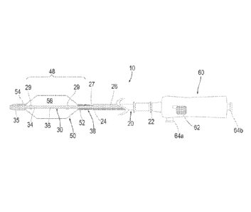
Turning to the drawings, FIGS. 1-2B show a first exemplary embodiment of an
apparatus 10 for treating a body lumen, e.g., for infusing fluid into a body
lumen, such as a
blood vessel, aorto-venous fistula, tubular graft, and the like (not shown),
and/or for
CA 02827641 2013-08-16
WO 2012/112949 PCT/US2012/025734
11
performing a procedure within the body lumen, e.g., dilating a stenosis or
other obstruction
within the body lumen, removing thrombus, objects, and/or obstructive material
from within
the body lumen, delivering a stent, stent-graft, prosthetic valve, or other
prosthesis (also not
shown), delivering one or more agents into the body lumen, and the like.
Generally, the
apparatus 10 includes a catheter, sheath, or other tubular outer member 20, a
shaft or other
elongate inner member 30, and an expandable balloon or other treatment element
50 carried
by the inner and/or outer members 20, 30, e.g., on a distal portion 48 of the
inner member
30 shown in FIG. 1.
The apparatus 10 may be operable in multiple modes, for example, to perform
various treatments or other functions within a body lumen, e.g., to reduce or
eliminate the
need to exchange multiple devices during a procedure within a body lumen. For
example,
the apparatus 10 may include a valve, e.g., including a sealing or valve
member 38,
operable in a first mode for infusing fluid into a body lumen (FIG. 2A), and a
second mode
to facilitate introduction into a patient's body and/or to inflate the balloon
50 (FIG. 2B), as
described further below.
As best seen in FIG. 1, the outer member 20 includes a proximal end 22 coupled
to a
handle 60, a distal end 24 sized for introduction into a body lumen, and a
first lumen 26
extending between the proximal end 22 and an outlet 27 in the distal end 24.
The outer
member 20 may have a substantially uniform construction along its length, or
alternatively,
the construction may be varied. For example, a proximal portion of the outer
member 20
may be substantially rigid or semi-rigid to facilitate advancement of the
apparatus 10 from
the proximal end 22, and/or a distal portion of the outer member 20 may be
flexible, e.g., to
facilitate bending and/or advancement through tortuous anatomy without
substantial risk of
kinking or buckling. In exemplary embodiments, the outer member 20 may be
formed from
one or more materials such as metal, plastic, e.g., PEEK, Grilamed L25, and
the like, or
composite materials. The outer member 20 may have a length between about
thirty and one
hundred thirty centimeters (30-130 cm) and an outer diameter between about 1.2
and 2.0
millimeters, and the first lumen 26 may have a diameter between about 1.0 and
1.8
millimeters.
The inner member 30 also includes a proximal end (not shown), a distal end 34,
and,
optionally, may include a second lumen 36 extending between the proximal end
and a distal
tip 35, which may be sized to slidably receive a guide wire, or other rail
(not shown)
therethrough, e.g., having a diameter between about 0.3 and 1.0 millimeter.
Alternatively,
CA 02827641 2013-08-16
WO 2012/112949 PCT/US2012/025734
12
as shown in FIG. 3A, a distal tip 35" may be provided on the apparatus 10" (or
any of the
other embodiments herein) that includes a relatively short guidewire lumen 36"
beyond the
balloon 50." As shown, the guidewire lumen 36" may communicate between a
distal port
36a" in the distal tip 35" and a proximal side port 36h" adjacent to the
distal end 54" of the
balloon 50." In this alternative, a guidewire (not shown) may be backloaded
into the distal
port 36a" through the guidewire lumen 36" and out the proximal port 36b",
e.g., to provide
a "rapid-exchange" lumen such that the guidewire need not be loaded through
the entire
length of the inner member 30." Thus, in this alternative, the second lumen 36
(shown in
FIGS. 1-2B) may be omitted.
The inner member 30 may have a substantially uniform construction along its
length, or alternatively, the construction may be varied, similar to the outer
member 20. For
example, the inner member 30 may be formed from a composite construction
including a
braided, helical, or other support structure, e.g., formed from metal, such as
stainless steel,
polymeric strong fiber, and the like, embedded in a polymeric matrix, e.g., a
thermoset
polymeric matrix, such as polyimide, that may resist the inner member 30
taking a shape set
when bent or curved. Optionally, the inner member 30 may include a tether wire
31
coupled between the proximal and distal ends 32, 34, e.g., bonded or otherwise
attached to
the valve member 38 and/or balloon 50, as shown in FIGS. 2A and 2B. The tether
wire 31
may be embedded in the shaft of the inner member 30 or may be free and/or
external to the
shaft other than at the valve member 38 and/or balloon 50, as shown. The
tether wire 31
may be a high strength, relatively small cross-section wire or filament that
may provide a
safety feature to prevent the balloon 50 from becoming loose from the
apparatus 10, e.g., if
the inner member 30 were somehow broken between the proximal and distal ends
32, 34
during use.
Returning to FIG. 1, the inner member 30 is sized to be slidably received
within the
first lumen 26 of the outer member 20, e.g., such that an annular space is
defined between
the outer and inner members 20, 30 for passing one or more fluids
therethrough, as
described further below. The inner member 30 may have a length relative to the
outer
member 20 such that the inner member proximal end is received within or
extends
proximally beyond the outer member proximal end 22, e.g., into the handle 60,
and the
inner member distal end 34 extends distally beyond the outlet 27 of the outer
member 20,
e.g., to define the distal portion 48, as described further below. The distal
tip 35 may have a
rounded, tapered, and/or other shape, e.g., to provide a substantially
atraumatic tip for the
CA 02827641 2013-08-16
WO 2012/112949 PCT/US2012/025734
13
apparatus 10, similar to embodiments in U.S. Patent No. 8,043,313 and U.S.
Publication
No. 2011/ 0125132.
The handle 60 may be coupled to or otherwise provided on the proximal end 22
of
the outer member 20, e.g., attached by one or more of an interference fit,
bonding with
adhesive, sonic welding, cooperating connectors (not shown), and the like. An
actuator 60
may be coupled to the proximal end of the inner member 30 for directing the
inner member
30 axially relative to the outer member 20, e.g., to open or close the outlet
27 and/or to
direct the apparatus 10 between the different modes, as described further
elsewhere herein.
The handle 60 may also include one or more ports 64, e.g., a first port 64a
communicating
with the first lumen 26, and a second port 64b communicating with the second
lumen 36,
similar to embodiments in the applications identified elsewhere herein.
The balloon 50 includes proximal and distal ends 52, 54 coupled to the distal
portion
48 of the inner member 30, e.g., a distal end 54 attached to the inner member
30, e.g.,
adjacent the distal tip 35, a proximal end 52 attached to the distal end 34 of
the inner
member 30 proximal to the distal tip 35, thereby defining a substantially
fluid-tight interior
56. For example, the distal end 54 of the balloon 50 may be attached or
otherwise secured
directly to the distal end 24 of the outer member 20 and/or to the distal tip
35 to provide a
fluid-tight connection, e.g., by one or more of bonding with adhesive,
interference fit, sonic
welding, fusing, engagement with a surrounding sleeve or other connector (not
shown), and
.. the like.
The balloon 50 may be formed from elastic material, e.g., to provide a
compliant or
semi-compliant balloon that may be expanded to a variety of sizes and/or
shapes, e.g., based
on the amount of fluid and/or pressure within the interior 56. Alternatively,
the balloon 50
may be formed from substantially inelastic material, e.g., to provide a non-
compliant
balloon that expands to a predetermined size when inflated substantially
independent of
pressure (once a minimum volume and/or pressure is introduced to achieve the
predetermined size). Such a non-compliant balloon 50 may expand to the
predetermined
size even if inflated to relatively high pressures, e.g., until the balloon 50
bursts or otherwise
ruptures, e.g., at pressures of at least ten atmospheres, twenty atmospheres,
thirty
atmospheres, and the like.
As best seen in FIGS. 2A and 2B, the sealing or valve member 38 is provided on
or
adjacent the distal portion 48 of the inner member 32, e.g., adjacent the
proximal end 52 of
the balloon 50. For example, the sealing member 38 may be attached to an outer
surface of
CA 02827641 2013-08-16
WO 2012/112949 PCT/US2012/025734
14
the inner member 30 and the proximal end 52 of the balloon 50 may be attached
to the
sealing member 38. As shown, the proximal end 52 of the balloon 50 extends at
least
partially over the sealing member 38 and may be attached to the sealing member
38, e.g., by
bonding with adhesive, sonic welding, fusing, interference fit, an exterior
collar (not
shown), and the like. Thus, the proximal end 52 of the balloon 50 may have a
substantially
fluid-tight seal with the sealing member 38 and consequently the inner member
30.
The sealing member 38 generally has a size to at least partially enter the
first lumen
26 of the outer member 20, e.g., such that the sealing member 38 may
substantially seal the
outlet 27 when the sealing member 38 is engaged with or received in the outlet
27 and/or
first lumen 26. For example, as best seen in FIG. 2B, the sealing member 38
may include a
valve body 38a and one or more annular valve seals 38b extending around the
valve body
38a. Although only a single valve seal 38b is shown, it will be appreciated
that a plurality
of valve seals (not shown) may be provided that are spaced apart axially from
one another
along a length of the valve body 38a, e.g., to enhance the resulting seal.
The valve body 38a may have an outer diameter slightly smaller than the inner
diameter of the first lumen 26 and/or outlet 27, e.g., such that the valve
body 38a may freely
enter the first lumen 26 through the outlet 27. The valve seal(s) 38b may have
an outer
diameter that is slightly larger than the inner diameter of the first lumen 26
such that the
valve seal(s) 38b slidably engage the inner surface of the outer member 20
when the valve
body 38a enters the first lumen 26. For example, the valve seal(s) 38b may be
formed from
resiliently flexible material, such as silicone or other elastomer, a low
Durometer (e.g., 40D)
PEBAX material, polyurethane, and the like, that may be sufficiently
compressible to
accommodate sliding into the first lumen 26 without creating substantial
friction, yet may
resist deformation under substantial fluid pressure, e.g., to maintain a
substantially fluid-
tight seal against the inner wall of the outer member 20.
Alternatively, the valve seal(s) 38b may be formed from relatively harder,
lubricious
material that has mechanical compressibility, e.g., polyethylene tubular or
other hollow
structure that may bend in response to applied loads. The valve body 38a may
be formed
from a different material than the valve seal(s) 38b, e.g., to provide a more
rigid base or
support for the valve seal(s) 38a, or may be formed from the same material,
e.g., integrally
molded, or otherwise formed from a single piece of material. Thus, the valve
seal(s) 38b
may slidably engage the inner surface of the outer member 20 to provide a
substantially
CA 02827641 2013-08-16
WO 2012/112949
PCT/US2012/025734
fluid-tight seal without requiring excessive force that may otherwise jam or
damage the
apparatus 10 during use.
Optionally, the sealing member 38 may have a tapered shape to facilitate
aligning
and/or receiving the sealing member 38 within the outlet 27. For example, as
shown in
5 .. FIGS. 2A and 2B, the valve body 38a may include a tapered proximal end
38c to guide the
sealing member 38 into the outlet 27 and first lumen 26, e.g., in case the
outer and inner
members 20, 30 become out of concentric alignment with one another during use.
Alternatively, as shown in FIGS. 3-4C, a sealing member 38' may be provided
that
has an outer diameter that is larger than the inner diameter of the outlet
27.' In this
10 alternative, the sealing member 38' may also include a tapered proximal
end 38c', e.g., to
facilitate the sealing member 38' engaging or being received at least
partially within the
outlet 27' of the outer member 20.' Thus, only the tapered proximal end 38e'
may be
received within the outlet 27' until the larger midsection of the sealing
member 38' abuts
the distal end 24' of the outer member 20' to provide a substantially fluid-
tight seal.
15 As best
seen in FIGS. 2A and 2B, the sealing member 38 may include one or more
passages 39 extending generally longitudinally between the proximal end 38c
and a distal
end 38d of the sealing member 38, e.g., a plurality of enclosed passages or
grooves formed
in the valve body 38a. For example, the valve body 38a may be formed as an
extrusion
including a bore for receiving the inner member 30 and one or more enclosed
passages 39
extending between the ends 38e, 38d. Alternatively, enclosed lumens may be
formed
within the wall of the tubing to provide the passage(s) 39 using other
methods. In a further
alternative, shown in FIGS. 3-4C, the sealing member 38' may be provided as a
length of
tubing with one or more longitudinal grooves formed in an inner surface
thereof. When the
sealing member 38' is attached to or otherwise placed around the inner member
30,' the
.. groove(s) may extend along the outer wall of the inner member 30,' thereby
together
defining the passage(s) 39.'
In addition or alternatively, if desired, the apparatus 10 may include one or
more
markers to facilitate positioning and/or advancement of the apparatus 10
during use. For
example, as best seen in FIG. 1, radiopaque markers 29 may be provided on the
distal
.. portion 48 of the inner member 30, e.g., aligned with or adjacent the
proximal and distal
ends 52, 54 of the balloon 50. In addition or alternatively, one or more
radiopaque markers
(not shown) may be provided on the outer member distal end 24, on the distal
tip 35, on the
balloon 50, e.g., on the proximal and/or distal ends 52, 54, and/or on the
sealing member(s)
CA 02827641 2013-08-16
WO 2012/112949 PCT/US2012/025734
16
38. Alternatively, one or more components of the apparatus 10 may be formed
from
radiopaque or other materials that may facilitate imaging the apparatus 10
during use. For
example, radiopaque markers and/or materials may facilitate positioning or
otherwise
imaging the apparatus 10 using fluoroscopy or other x-ray imaging, e.g., when
positioning
the balloon 50 (either before or after expansion) and/or when infusing fluid
via the outlet
27. Alternatively, echogenic markers and/or materials may be provided to
facilitate
imaging using ultrasound or similar imaging techniques.
Returning to FIGS. 1-2B, during assembly, the sealing member 38 may be placed
around the inner member 30 at the desired location on the distal end 34, e.g.,
proximal to the
desired length for the distal portion 48 and attached thereto, e.g., by
bonding with adhesive,
sonic welding, fusing, heat shrinking, and the like. The proximal end 52 of
the balloon 50
may then be positioned partially over the sealing member 38 and attached
thereto. Thus, the
passage(s) 39 may communicate from the outside of the proximal end 38c of the
sealing
member 38 with the interior 56 of the balloon 50. The distal tip 35 may be
attached to the
inner member 30, e.g., by an interference fit, bonding with adhesive,
cooperating
connectors, sonic welding, fusing, and the like. The distal end 54 of the
balloon 50 may be
attached to the distal end 34 of the inner member 30, e.g., closer to or over
the distal tip 35.
Consequently, the interior 56 of the balloon 50 may be substantially sealed
other than the
passage(s) 39 through the sealing member 38.
With additional reference to FIG. 1, the outer member 20 may be positioned
around
the inner member 30 and the handle 60 and actuator 62 may be coupled to the
outer and
inner members 20, 30, respectively, e.g., similar to embodiments disclosed in
the
applications identified elsewhere herein. The apparatus 10 may be operable in
a first mode
for delivering fluid into a body lumen (not shown) into which the apparatus
1010 is
introduced (or otherwise exterior to the distal end 24 of the outer member 20)
and a second
mode for inflating the balloon 50.
For example, the inner member 30 may be movable between a first or distal
position, shown in FIG. 2A, where the sealing member 38 is spaced apart from
the outlet 27
of the outer member 20, and a second or proximal position, shown in FIG. 2B,
where the
sealing member 38 at least partially enters the outlet 27 and first lumen 26.
In the first
position, fluid delivered through the lumen 26 of the outer member 20 may exit
the outlet 27
and enter the body lumen or other exterior environment, e.g., proximal to the
distal portion
48. In the second position, the valve seal(s) 38b may substantially seal the
outlet 27 such
CA 02827641 2013-08-16
WO 2012/112949 PCT/US2012/025734
17
that fluid delivered through the lumen 26 may enter through the passage(s) 39
in the sealing
member 38 and into the interior 56 of the balloon 50, thereby inflating the
balloon 50. In
addition, in the second position, a vacuum may be applied to the first lumen
26 to aspirate
inflation media from the interior 56, e.g., to collapse the balloon 50 when
desired.
Turning to FIG. 5, an alternative embodiment of the apparatus 110 is shown
similar
to the apparatus 10, 10' described above. The apparatus 110 includes an outer
member 120,
an inner member 130, a balloon 150, and a sealing member 138 similar to the
apparatus 10,
10.' The apparatus 110 may be operable in first and second modes by directing
the inner
member 130 between a first or distal position and a second or proximal
position, also
similar to the apparatus 10, 10.'
However, unlike the previous embodiments, the apparatus 110 includes a spring
or
other biasing mechanism 190 coupled between the inner and outer members 130,
120 for
biasing the inner member 130 to one of the first and second positions. For
example, as
shown, the spring 190 may bias the inner member 130 towards the proximal
position, i.e.,
such that the outlet 127 of the apparatus 110 is normally closed and/or to
enhance sealing
the outlet 127 with the sealing member 138. The bias may be overcome by
directing the
inner member 130 distally to unseat the sealing member 138 and open the outlet
127.
As shown, the spring 190 includes a first end 192 attached or otherwise
coupled to
the distal end 124 of the outer member 120, and a second end 194 attached or
otherwise
coupled to the distal end 134 of the inner member 130 and/or the sealing
member 138. For
example, the second end 194 of the spring 190 may be attached between the
sealing
member 138 and the inner member 130 or otherwise to the sealing member 138,
while still
accommodating the passage 139 extending through the sealing member 138. In
exemplary
embodiments, the ends 192, 194 of the spring 190 may be attached to the inner
and outer
members 130, 120 by bonding with adhesive, sonic welding, fusing, interference
fit, one or
more connectors (not shown), and the like.
The relative diameter of the spring 190 and the inner member 130 may be set to
reduce the risk of over-extension of the spring 190. For example, the spring
190 may be
relaxed or under slight tension when the inner member 130 is in the proximal
position and
may be placed under higher tension when the inner member 130 is directed
distally. As the
spring 190 is placed under higher tension, the diameter of the spring 190 may
decrease
thereby increasing friction between the spring 190 and the inner member 130.
This
increasing friction may reduce the risk of over-extending the spring 190,
which may
CA 02827641 2013-08-16
WO 2012/112949
PCT/US2012/025734
18
otherwise plastically deform the spring 190 or otherwise prevent the spring
190 from
subsequently biasing the inner member 130 proximally towards the proximal
position.
Turning to FIG. 6, yet another alternative embodiment of the apparatus 110' is
shown similar to the apparatus 110 of FIG. 5. The apparatus 110' includes an
outer member
120,' an inner member 130,' a balloon 150,' a sealing member 138,' and a
spring 190,'
similar to the apparatus 110. The apparatus 110' may be operable in first and
second modes
by directing the inner member 130' between a first or distal position and a
second or
proximal position, also similar to the apparatus 10, 10.'
In addition, the apparatus 110' includes a helical member 170' within the
balloon
150' that may be expanded to an expanded helical shape, similar to embodiments
in the
applications identified elsewhere herein. For example, the helical member 170'
may
include a first or proximal end coupled to the outer member 120' (not shown)
and a second
or distal end 174' coupled to the inner member 130,' adjacent the distal end
154' of the
balloon 150.' Thus, the apparatus 110' may also be operated in a third mode,
e.g., by
directing the inner member 130' proximally from the second position to a third
position in
which the helical member 170' is axially compressed and radially expanded. The
balloon
150' may remain collapsed while the helical member 170' is expanded or may be
inflated
and then collapsed after the helical member 170' is expanded, similar to
embodiments in the
applications identified elsewhere herein.
After the helical member 170' and balloon 150' are used to remove material in
the
expanded helical shape, the inner member 130' may be directed distally to
return the helical
member 170' to its original contracted shape around the inner member 130.'
This action
may extend the spring 190' and open the outlet 127.' However, as discussed
above, the
relative sizes of the spring 190' and the inner member 130' may be such that
the spring 190'
compresses as it extends and frictionally engages the inner member 130,'
thereby reducing
the risk of the spring 190' over-extending while the inner member 130' is
directed distally.
Turning to FIGS. 21A-22B, another embodiment of an apparatus 810 is shown,
which may be similar to the apparatus 10, 10' described above (or one or more
of features
of the apparatus 810 may be incorporated into any of the embodiments described
herein).
The apparatus 810 generally includes an outer member 820 including proximal
and distal
ends 822, 824, an inner member 830 including proximal and distal ends 832,
834, a balloon
850 including proximal and distal ends 852, 854, and a sealing member 838
similar to the
apparatus 10, 10.'
CA 02827641 2013-08-16
WO 2012/112949 PCT/US2012/025734
19
The apparatus 810 also includes a flexible distal tip 835 extending from the
distal
end 834 of the inner member 830 that has a "J" tip or other curved shape.
Optionally, the
distal tip 835 may have a tapered shape that narrows distally from the balloon
850 or may
have a substantially uniform cross-section (not shown), if desired. The distal
tip 835 may
be biased to the curved shape yet may be resiliently flexible such that the
distal tip 835 may
be at least partially straightened, e.g., by directing a guidewire or other
rail 99 having
greater rigidity than the distal tip 835 through the distal tip 835, as shown
in FIG. 21C.
Thus, with the guidewire 99 removed from the distal tip 835, the distal tip
835 may
resiliently adopt its curved shape, as shown in FIGS. 21A and 21B, e.g., to
facilitate
advancement of the apparatus 810 through a patient's body. However, if
desired, the distal
tip 835 may be straightened, e.g., by introducing the guidewire 99
therethrough, to
accommodate advancing the apparatus 810 over the guidewire 99, as shown in
FIG. 21C.
The apparatus 810 may be operable in first and second modes by directing the
inner
member 830 between a first or distal position where the valve is open (see
FIG. 22A), and a
second or proximal position (see FIG. 22B) where the valve is closed, similar
to other
embodiments herein. For example, a handle 860 may be provided on the proximal
end 822
of the outer member, and an actuator 862 may be coupled to the proximal end
832 of the
inner member 830, similar to other embodiments herein. The actuator 862 may be
movable
axially, i.e., proximally and distally relative to the handle 860 for
directing the inner
member 830 between the proximal and distal positions.
In addition, unlike the previous embodiments, the actuator 862 and inner
member
830 may be rotatable about a longitudinal axis of the apparatus 810. Thus, the
actuator 862
may be rotated relative to the handle 860 to rotate the inner member 830 and
thereby change
the orientation of the curved distal tip 835. For example, FIGS. 21A and 21B
show the
curved distal tip 835 in opposite orientations, which may be achieved by
rotating the
actuator 862 about one hundred eighty degrees (180 ) relative to the handle
860. Thus,
rather than rotating the entire apparatus 810, i.e., including both the outer
and inner
members 820, 830 to change the orientation of the distal tip 835, only the
inner member 830
need be rotated. If the entire apparatus 810 were rotated, the outer member
820 may
become twisted or otherwise fail to transmit substantial torque between its
proximal and
distal ends 822, 824, e.g., if the outer member 820 is formed from polymeric
material
having poor torque transmission. Instead, the inner member 830 may be
decoupled from
CA 02827641 2013-08-16
WO 2012/112949 PCT/US2012/025734
the outer member 820, i.e., freely rotatable therein, thereby facilitating
transmitting torque
freely between the proximal and distal ends 832, 834.
To facilitate transmission of such rotation between the proximal and distal
ends 832,
834 of the inner member 830, the shaft of the inner member 830 may be formed
from a
5 composite or other construction that resists twisting. For example, the
inner member 830
may be formed from a stainless steel (or other metal or polymeric strong
fiber) braid in a
polymeric matrix (e.g., a thermoset polymeric matrix, such as polyimide, that
resists the
inner member 830 taking a shape set when bent or curved). Such construction
may provide
good flexibility while also maintaining substantial torque transmission
between the
10 proximal and distal ends 832, 834.
The actuator 862 may be freely rotatable relative to the handle 860, if
desired.
Alternatively, cooperating features (not shown) may be provided, e.g., on the
handle 860
and inner member 830, to limit rotation of the actuator 862 and inner member
830. For
example, one or more detents or tracks (not shown) may be provided within the
handle 860
15 .. and/or on the proximal end 832 of the inner member 830 that interact to
limit rotation to less
than three hundred sixty degrees (360 ). Thus, a user may be able to rotate
the actuator 862
to change the orientation of the curved distal tip 835 close to a complete
rotation, while
limiting excessive rotation in one direction, which may otherwise apply
excessive torque on
the inner member 830.
20 To allow rotation of the inner member 830 relative to the outer member
820, the
actuator 862 may be directed to the first position, thereby opening the valve
and decoupling
the distal end 824 of the outer member 820 from the sealing member 838 and,
consequently,
from the inner member 830. In the first position, the inner member 830 may be
rotated
relative to outer member 820 to change the orientation of the distal tip 835.
Optionally, the sealing member 838 and/or outer member 820 may be constructed
to
minimize friction therebetween, e.g., to allow rotation of the inner member
830 in the
second position with the valve closed. In this option, materials having a
relatively low
coefficient of friction, e.g., PTFE, polyethylene, and the like, may be
provided, e.g., on the
outer surface of the sealing member 838 and/or on the inner surface of the
distal end 824 of
.. the outer member 820. Thus, rather than having to open the valve to
decouple the outer and
inner members 820, 830, the members may freely rotate relative to one another
even with
the valve closed.
CA 02827641 2013-08-16
WO 2012/112949 PCT/US2012/025734
21
Returning to FIGS. 1-2B, the apparatus 10 (or any of the embodiments herein)
may
be introduced into a body lumen (not shown), e.g., via a patient's vasculature
or other
natural or surgically created passages, to perform one or more therapeutic
and/or diagnostic
medical procedures. In an exemplary embodiment, the target body lumen may be a
blood
vessel, e.g., a vein or artery, a graft, e.g., an aorto-venous fistula,
tubular xenograft, or
synthetic tubular graft, and the like. For example, the body lumen may be a
passage
communicating between an adjacent artery and vein (not shown), e.g., in an arm
or other
region of a dialysis patient. Alternatively, the body lumen may be a blood
vessel within a
patient's vasculature, e.g., a peripheral vessel in a patient's leg, a
cerebral vessel, and the
like. In a further alternative, the material may be a stone within a patient's
urinary tract or
other foreign object to be removed from the patient's body. In yet another
alternative, the
body lumen may be an aorta or a chamber of a heart, e.g., the site of a heart
valve in need of
repair, replacement, or other treatment.
Optionally, the body lumen may be accessed using one or more additional
instruments (not shown), which may be part of a system or kit including the
apparatus 10.
For example, an introducer sheath, guide catheter, or other tubular member
(not shown)
may be introduced adjacent the target treatment site where material is to be
removed, or
may be introduced elsewhere in the patient's body to provide access to the
patient's
vasculature or other passages communicating with the body lumen. If the body
lumen is
located in a peripheral vessel of the patient's vasculature, a percutaneous
puncture or cut-
down may be created using a needle or other instrument (not shown) at a
peripheral
location, such as a femoral artery, carotid artery, or other entry site (also
not shown), and an
introducer sheath may be placed through the puncture at the peripheral
location to provide
access. The apparatus 10 may be advanced through the patient's vasculature
from the entry
site, e.g., alone or with the aid of a guide catheter, guidewire, and the like
(not shown).
For example, to facilitate directing the apparatus 10 from an entry site to
the target
body lumen, a guide catheter, micro-catheter, or other tubular body may be
placed from the
entry site to the body lumen using conventional methods. In addition or
alternatively, a
guidewire (not shown) may be placed from the entry site to the body lumen if
desired, e.g.,
if the inner member 30 includes the second lumen 36. Alternatively, if the
apparatus 10
includes a rapid-exchange guidewire lumen in its distal tip, the guidewire may
be
backloaded through the distal tip to facilitate advancing the apparatus 10
along the
guidewire. Optionally, the guide catheter or tubular body may also be used for
aspiration,
CA 02827641 2013-08-16
WO 2012/112949 PCT/US2012/025734
22
e.g., coupled to a source of vacuum for capturing material removed by the
apparatus 10, as
described further below.
Initially, with reference to FIG. 2A, the apparatus 10 may be provided with
the inner
member 30 in the second position and the sealing member 38 substantially
sealing the outlet
27. In this position, the sealing member 38 may also provide a substantially
smooth
transition for the distal end 24 of the outer member 20 (in addition to
sealing the outlet 27),
e.g., which may facilitate advancement of the apparatus 10 with minimal risk
of damaging
the walls of body lumens, e.g., when the apparatus 10 is advanced through
tortuous
anatomy. Alternatively, the apparatus 10 may be introduced with the inner
member 30 in
the first position, i.e., with the outlet 27 open, if desired, to facilitate
delivery of fluids
during manipulation of the apparatus 10.
If the apparatus 10 includes a curved distal tip (not shown), e.g., similar to
the
apparatus 810 shown in FIGS. 21A-22B, the distal tip may be straightened
during
advancement over a guidewire or other rail. If desired to deploy the distal
tip in its curved
shape, the guidewire may be withdrawn partially until removed from the distal
tip,
whereupon the distal tip may resiliently return to its curved shape. The
curved tip may then
be rotated, e.g., by rotating the inner member if the inner member is
rotatable independent
of the outer member or the entire apparatus 10, to access a branch or
otherwise facilitate
advancement of the apparatus 10 from one body lumen into another. For example,
once the
curved tip is rotated and the apparatus manipulated sufficiently within a body
lumen, e.g., to
advance the distal tip into a branch adjacent the body lumen, the guidewire
may be
advanced again to straighten the distal tip and advance the guidewire before
advancing the
apparatus 10 further.
At any time, if it is desired to deliver fluid into the body lumen, the inner
member 30
may be directed to (if not already in) the distal or first position to space
the sealing member
38 from the distal end 24 of the outer member 20 and open the outlet 27 (FIG.
2A). Fluid
may then be delivered through the lumen 26 of the outer member and out the
outlet 27 into
the body lumen. Because the outlet 27 is spaced away from the sealing member
38,
substantially all of the fluid is injected into the body lumen and does not
pass through the
.. passage(s) 39 into the balloon 50.
For example, radiopaque contrast or other fluid may be delivered into the body
lumen via the annular passage defined by the first lumen 26 between the outer
and inner
members 20, 30 to facilitate monitoring and/or identifying the location of the
distal portion
CA 02827641 2013-08-16
WO 2012/112949
PCT/US2012/025734
23
48 and/or a target treatment site. Markers 29 (and/or other markers, not
shown) on the
apparatus 10 may facilitate positioning the balloon 50 relative to the
treatment site. For
example, contrast may facilitate identifying obstructive material intended to
be dilated or
removed within a body lumen, an implantation site for a prosthesis, and the
like before the
balloon 50 is expanded, e.g., to facilitate verifying that the balloon 50 is
positioned within
or adjacent the treatment site.
As best seen in FIG. 2B, when it is desired to expand the balloon 50 (and/or
otherwise perform a procedure involving another treatment element, not shown,
on the
distal portion 48), the inner member 30 may be directed to (or may be
automatically biased
to) the proximal or second position, e.g., to substantially seal the outlet 27
with the sealing
member 38 (FIG. 37B). The sealing member 38 may provide a substantially fluid-
tight seal
of the outlet 27 such that subsequent fluid delivery through the first lumen
26 causes the
fluid to pass through the passage(s) 39 of the sealing member 38 into the
interior 56 of the
balloon 50, thereby inflating the balloon 50.
For example, during an exemplary procedure, the apparatus 10 may be positioned
until the distal portion 48 and balloon 50 are positioned distally beyond an
obstructed region
within a body lumen. With the inner member 30 in the second position sealing
the outlet
27, the balloon 50 may be inflated within the body lumen, e.g., such that the
balloon 50
extends substantially entirely across the body lumen. The entire apparatus 10
may then be
retracted to pull the material from the body lumen, e.g., to be aspirated into
a guide catheter
(not shown), or otherwise removed from the body lumen. Optionally, the balloon
50 may
be directable to a helical configuration, similar to the apparatus in the
applications identified
elsewhere herein, e.g., to facilitate removal of material within the body
lumen.
Once material is removed, the inner member 30 may be directed back towards the
second position, and fluid may be introduced through the outlet 27 to observe
the amount of
material removed and/or remaining within the body lumen. If additional
material is to be
removed, the inner member 30 may be directed to the first position, e.g., if
desired to
advance the apparatus 10 through additional material to be removed. Once the
balloon 50 is
located beyond the material, the process may be repeated as often as desired
with the valve
opened and closed to monitor the position of the balloon 50 and/or progress of
removal.
In addition, if desired, the obstructive material may be treated, e.g., at
least partially
dissolved, macerated, and the like before, during, or after withdrawal. For
example, a
therapeutic agent may be delivered into the body lumen via the first lumen 26
and outlet 27
CA 02827641 2013-08-16
WO 2012/112949 PCT/US2012/025734
24
of the outer member 20, e.g., to at least partially dissolve or separate
thrombus or other
relatively soft material before being removed by the balloon 50 and/or
otherwise to treat the
wall of the body lumen.
To collapse the balloon 50, e.g., after inflating the balloon 50 to remove
material,
dilate an obstruction, and/or otherwise treat a body lumen, fluid may be
evacuated from the
interior 56 through the passage(s) 39 and the first lumen 26. Alternatively,
the inner
member 30 may be directed towards the first position to disengage the sealing
member 38
and open the outlet 27. The fluid within the balloon 50 may then be free to
escape through
the passage(s) 39 into the body lumen and deflate the balloon 50 without
requiring
aspiration.
Optionally, if desired, the inner member 30 may be positioned at an
intermediate
position, i.e., between the first and second positions, e.g., as shown in FIG.
15B, in which
fluid delivered from the outlet 27 may be divided such that some fluid enters
the passage(s)
39 and expands the balloon 50 while the remaining fluid is delivered into the
body lumen,
as described further below. The relative amount of inflation and fluid
delivery into the body
lumen may be adjusted, as desired, simply by directing the inner member 30
proximally or
distally to move the sealing member 38 closer to or further from the outlet
27. This
procedure may be accomplished using external imaging, e.g., if the fluid
includes
radiopaque contrast, to monitor the inflation and/or position of the balloon
50 and/or the
surrounding vasculature within which the balloon 50 is located.
In another option, the apparatus 10 may be used to deliver and aspirate fluid
using
the outlet 27. For example, a user may want to deliver and remove one or more
diagnostic
and/or therapeutic agents within a body lumen using the apparatus 10. In one
example,
contrast, dyes, or other material for facilitating imaging may be delivered
into the body
lumen from the outlet 27 (with the inner member 30 and sealing member 38 in
the first
position) and then aspirated back into the outlet 27 to reduce the amount of
contrast that
remains within the body lumen or travels to other locations in the patient's
body. In
addition or alternatively, the outer member 20 may include one or more
additional lumens
(not shown, see, e.g., FIG. 14B) extending between the proximal and distal
ends 22, 24, if
desired, e.g., for delivering and/or aspirating material into/from an exterior
environment
adjacent the distal end 24.
In another example, a lytic agent may be delivered into the body lumen, e.g.,
to
break up clot or other material within the body lumen, and then loose material
may then be
CA 02827641 2013-08-16
WO 2012/112949
PCT/US2012/025734
aspirated into the outlet 27 and through the lumen 26 (or into a guide
catheter, not shown,
positioned over the apparatus 10), which may reduce the risk of bleeding or
otherwise
exposing the lytic agent systemically to the patient's body. The outlet 27 may
also be used
to aspirate pieces of thrombus or other material that is not dissolved or
broken down by the
5 agent and/or is otherwise loosened within the body lumen. During such
procedures, the
balloon 50 may be at least partially inflated, e.g., by directing the inner
member 30 to an
intermediate position, as shown in FIG. 15B, to stop or reduce flow through
the body lumen
while the one or more agents are delivered and aspirated, which may also
reduce exposure
of other locations to the agent(s) delivered into the body lumen.
10 With the
apparatus 10 and procedures described herein, the first lumen 26 may be
used for both inflation of the balloon 50 and delivering fluid into the body
lumen. Thus, the
profile of the outer member 20 and therefore of the overall apparatus 10 may
be smaller
than devices that include separate inflation and infusion lumens. Further,
although the
second lumen 36 of the inner member 30 could be used for infusion of fluids,
this would
15 generally require removing the guidewire over which the apparatus 10 is
introduced since
the guidewire may substantially fill the second lumen 36. Because the first
lumen 26 may
be used for infusion, the guidewire may remain within the second lumen 36
throughout the
procedure, thereby potentially reducing the number of guidewire or other
device exchanges.
Further, the apparatus 10 may remain over the guidewire, which may facilitate
advancing
20 the apparatus 10 to other target body lumens intended for treatment, as
explained in the
applications identified elsewhere herein.
Turning to FIG. 16A, in another exemplary method, the body lumen 90 may
include
an occlusion 94, e.g., a partial or chronic total occlusion within a blood
vessel, and the
apparatus 10 may be introduced to dilate and/or otherwise treat the occlusion
94. As shown,
25 a guidewire 99 has been tracked from an entry site (not shown) into the
body lumen 90 and
through the occlusion 94, e.g., using known methods. Chronic total lesions may
be
particularly difficult to treat because there is little opportunity to perform
conventional dye
injections to facilitate imaging since there is no flow through the body lumen
90. Further, it
may be difficult to track and/or position the guidewire 99 and/or apparatus 10
within the
body lumen 90 without using dye injections.
Initially, the apparatus 10 may be advanced into the body lumen 90 with the
balloon
50 in its collapsed condition. For example, the apparatus 10 may be advanced
over the
guidewire 99 previously placed through the occlusion 94, e.g., until the
distal end 54 of the
CA 02827641 2013-08-16
WO 2012/112949 PCT/US2012/025734
26
balloon 50 enters the region of the body lumen 90 beyond the occlusion 94, as
shown. With
the balloon 50 positioned at least partially within the occlusion 94, the
inner member 30
may be directed to open the outlet 27, and radiopaque contrast, dye, or other
fluid
(represented by 95) may be delivered into the body lumen 90 via the annular
passage
defined by the first lumen 26 between the outer and inner members 20, 30 to
facilitate
locating and/or measuring the size of the material of the occlusion 94 and/or
body lumen 90,
e.g., using fluoroscopy. Markers 29 (not shown in FIG. 16A, see FIG. 1) on the
apparatus
may facilitate positioning the balloon 50 relative to the occlusion 94 before
the balloon
50 is expanded, e.g., to facilitate verifying that the balloon 50 is
positioned through and/or
10 across the occlusion 94. If desired, the inner member 30 may be directed
back and forth
between the first and second positions, e.g., to allow infusion of contrast
and inflation of the
balloon 50 to dilate the occlusion 94 and monitor the progress of the
treatment.
Thus, the apparatus 10 may facilitate dye injection adjacent the occlusion 94
while
maintaining the guidewire 99 in position. Unlike the apparatus 10,
conventional devices
may require removing a guidewire or other device advanced through the
occlusion 94 to
allow dye injections and imaging around the occlusion 94. In such procedures,
it may be
difficult to reintroduce the guidewire or other device back through the small
passage created
through the occlusion 94.
If desired, obstructive material may be treated, e.g., at least partially
dissolved,
macerated, and the like before, during, or after withdrawal. For example, a
therapeutic
agent may be delivered into the body lumen 90 via the first lumen 26 and
outlet 27 of the
outer member 20, e.g., to at least partially dissolve or separate thrombus or
other relatively
soft material before being dilated by the balloon 50. In addition or
alternatively, the distal
portion 48 may carry one or more other treatment elements, e.g., an abrasive
tip, a passive
or active atherectomy tool, and the like (not shown), in addition to or
instead of the balloon
50. Exemplary tips and methods for using them are disclosed in application
Serial No.
12/966,925, filed December 13, 2010, published as U.S. Publication No. 2011/
0172598.
Optionally, as shown in FIG. 16B, a stent 96 may be carried by the balloon 50
and
may be expanded by inflating the balloon 50. For example, with the valve of
the apparatus
10 open, dye 95 may be injected into the body lumen 90 to facilitate imaging
and
positioning the apparatus 10. Once the stent 96 is positioned across the
occlusion 94, the
valve may be closed, and the balloon 50 may be inflated to expand the stent 96
and dilate
CA 02827641 2013-08-16
WO 2012/112949 PCT/US2012/025734
27
the occlusion 94 (not shown). Once the stent 96 is expanded, the balloon 50
may be
collapsed and the apparatus 10 removed from the body lumen 90 and patient's
body.
Alternatively, the apparatus 10 may be used to introduce and/or deploy other
prostheses instead of or in addition to the stent 96. For example, a tubular
stent-graft, one
or more components of a prosthetic valve, and the like (not shown) may be
carried by the
distal portion 48, e.g., over the balloon 50. The prosthesis may be expanded
or otherwise
deployed within a body lumen, e.g., by inflating the balloon 50, as described
above, with
fluid being selectively introduced, as desired.
Turning to FIG. 16C, in another method, the apparatus 10" may be used as a
drug
delivery platform for treating the occlusion 94. For example, in some
applications, it may
be desirable to deliver an anti-restenosis drug without a stent. As shown, the
apparatus 10"
includes a carrier 98" provided over the balloon 50" that may be delivered
into the body
lumen 90 and/or through the occlusion 94." For example, similar to the methods
described
above, the apparatus 10" may be advanced into the body lumen 90 with the
balloon 50" and
the carrier 98" thereon in a collapsed condition, e.g., over the guidewire 99.
With the balloon 50" positioned within the occlusion 94 and the valve open,
contrast, dye, or other fluid 95 may be delivered from the outlet 27" into the
body lumen 90
to facilitate locating and/or measuring the size of the occlusion 94 and/or
body lumen 90,
e.g., using fluoroscopy. Once the apparatus 10" is positioned with the balloon
50" across
the occlusion 94, the valve may be closed and the balloon 50" inflated within
the body
lumen 90 to dilate the occlusion 94 and deliver the carrier 98." Once the
carrier 98" is
delivered, the balloon 50" may be collapsed and the apparatus 10" removed from
the body
lumen 90 and patient's body. One or more therapeutic agents may be positioned
within or
otherwise carried by the carrier 98" and, therefore, may remain within the
dilated occlusion
94 to treat the body lumen 90.
Alternatively, the agent(s) may be delivered directly from the wall of the
balloon
50." For example, the agent(s) may be infused through the wall of the balloon
50," e.g., by
providing a porous layer on the balloon 50" into which the agent(s) may be
embedded or
otherwise placed. In another alternative, the agent delivered into the body
lumen 90 may be
provided from multiple components that may react or interact in situ once
delivered together
within the body lumen 90. For example, a first component (or one or more
additional
components less than all components of the agent) may be carried on the wall
of the balloon
50," e.g., in a porous layer or on a carrier 98" disposed around the balloon
50," as described
CA 02827641 2013-08-16
WO 2012/112949 PCT/US2012/025734
28
above. The second component (or multiple remaining components needed for the
agent)
may be delivered via the outlet 27" on the apparatus 10." For example, after
one or more
components are delivered by closing the valve and inflating the balloon 50"
within the
occlusion 94, the valve may be opened and a fluid carrying the one or more
remaining
components may be delivered into the body lumen 90. The components may then
combine
to form an active drug or agent that may treat the material of the occlusion
94 and/or
otherwise treat the body lumen 90.
In another alternative, a balloon (not shown) may be provided on the distal
end 24 of
the outer member 20 or on the distal portion 48 of the inner member 30 distal
to the balloon
50, if desired, similar to embodiments in the applications identified
elsewhere herein. Such
a balloon may be a non-compliant, high pressure balloon, e.g., for dilating
the body lumen,
or an elastic, compliant balloon for substantially sealing the body lumen to
isolate one or
more regions of the body lumen before infusion of fluid therein. In such
alternatives, the
outer and/or inner members 20, 30 may include one or more additional lumens,
e.g., as
shown in FIGS. 14A-14C, providing inflation lumens for such additional
balloons.
Turning to FIGS. 7A-7C, another embodiment of an apparatus 210 is shown that
includes a tubular outer member 220, an elongate inner member 230, and a
distal portion
248 carrying a treatment element, e.g., a stent or other prosthesis 296
covered by a cover or
other constraint 298. Generally, the apparatus 210 may be operable in multiple
modes, e.g.,
first and second modes, by directing the inner member 230 between a first or
distal position
and a second or proximal position for opening and closing a valve adjacent the
distal portion
248, similar to other embodiments herein. In addition, the apparatus 210 may
be operable
for deploying the prosthesis carried on the distal portion 248, as described
further below.
The outer member 220 includes a proximal end 222 coupled to a handle 260, a
distal
end 224 sized for introduction into a body lumen, and a first lumen 226
extending between
the proximal end 222 and an outlet 227 in the distal end 224. The inner member
230 also
includes a proximal end 232, a distal end 234, and, optionally, may include a
second lumen
236 extending between the proximal end 232 and a distal tip 235. In addition,
the inner
member 230 may include an actuator member (not shown), e.g., slidably disposed
within an
actuator lumen (also not shown), coupled with the constraint 298 for
selectively actuating
the constraint 298, e.g., advancing the constraint distally or otherwise to
deploy the
prosthesis 296, as described further below.
CA 02827641 2013-08-16
WO 2012/112949 PCT/US2012/025734
29
The inner member 230 may have a length relative to the outer member 220 such
that
the inner member proximal end 230 is coupled to an actuator 264 on the handle
260, and the
inner member distal end 234 extends distally beyond the outlet 227 of the
outer member
220, e.g., to define the distal portion 248. The actuator 260 may be coupled
to the proximal
end 232 of the inner member 230 for directing the inner member 230 axially
relative to the
outer member 220, e.g., to open or close the outlet 227 and/or to direct the
apparatus 210
between the different modes, similar to other embodiments herein.
Unlike the previous embodiments, the distal portion 248 includes the
prosthesis 296
and constraint 298 adjacent a tapered proximal portion 238, extending at least
partially
between the proximal portion 238 and the distal tip 235. The tapered portion
238 may taper
outwardly and distally from the inner member 230 to define an outer diameter
similar to or
larger than the outlet 227 of the outer member 220, e.g., to provide a sealing
member for
selectively sealing the outlet 227, similar to other embodiments herein. The
tapered portion
238 may be formed from material similar to the rest of the distal portion 248,
or the tapered
portion 238 may be formed from flexible and/or resilient material to enhance
the seal with
the outlet 227.
The inner member 230 may be movable between a first or distal position, shown
in
FIG. 7B, where the outlet 227 is spaced apart from the proximal portion 238,
and a second
or proximal position, shown in FIG. 7A, where the tapered portion 238 engages
the outlet
227 to substantially seal the outlet 227. For example, the actuator 262 may be
directed
between distal and proximal positions on the handle 260 to open and close the
outlet 227, as
shown, e.g., to allow fluid to be delivered from the first lumen 226 through
the outlet 227
into a body lumen or other region adjacent the distal portion 248.
The distal portion 248 may have an outer diameter similar to the maximum
diameter
of the tapered portion 238, e.g., a substantially uniform diameter between the
tapered
portion 238 and the distal tip 235. Alternatively, the distal portion 248 may
step down from
the tapered portion 238, e.g., to accommodate receiving the prosthesis 296
thereon.
As shown, the constraint 298 may be movable from a first position overlying
the
stent 296 and a second position for exposing the stent 296. As best seen in
FIG. 7C, an
actuator 266 on the handle 260 may be advanced distally to direct an actuator
member (not
shown) in the inner member 330 and consequently the constraint 298 distally to
expose the
stent 296. In the embodiment shown, the stent 296 may be self-expanding, i.e.,
biased to
expand to a diameter larger than a body lumen within which the stent 296 is
intended to be
CA 02827641 2013-08-16
WO 2012/112949 PCT/US2012/025734
deployed. Thus, as the constraint 298 is advanced, the stent 296 may
resiliently expand as it
is exposed until the constraint 298 is advanced sufficiently to expose the
entire stent 296.
Alternatively, other constraints may be provided instead of the sleeve 298
shown, e.g., one
or filaments or elements (not shown) that may surround the stent 296 and/or
secure the stent
5 296 on the distal portion 248 in a constrained state, yet may be
withdrawn to release the
stent 296 from the constrained state and allow the stent 296 to resiliently
expand to a
deployed state.
In addition or alternatively, a balloon or other expandable member (not shown)
may
be provided on the distal portion 248, e.g., underlying the stent 296. In this
embodiment,
10 the balloon may be inflated, e.g., by delivering fluid through the first
lumen 266 with the
inner member 230 in the second position such that the fluid passes through the
outlet 227
and one or more passages (not shown) in the tapered portion 238 into an
interior of the
balloon. For example, the balloon may be inflated to plastically or otherwise
further expand
the stent 296 after deployment and/or dilate the body lumen within which the
stent 296 is
15 deployed.
In a further alternative, the stent 296 may be plastically expandable, e.g.,
similar to
the embodiments described elsewhere herein. In this alternative, the
constraint 298 may
still be provided, if it is desired to protect the stent 296 (or other
prosthesis) and/or provide a
transition over the distal portion 248. Alternatively, the constraint 298 may
be omitted and
20 the stent 296 may be maintained on the distal portion 248, e.g., by
compressing the stent
296 or by the stent 296 having a substantially relaxed state corresponding to
the constrained
state. In this alternative, a balloon or other expandable member (not shown)
may be
provided on the distal portion 248 to expand the stent 296, similar to other
embodiments
herein.
25 Turning to FIGS. 8A and 8B, another embodiment of an apparatus 310 is
shown that
includes a tubular outer member 320, an elongate inner member 330, and a
distal portion
348, which may carry a treatment element, e.g., a balloon, stent or other
prosthesis, and the
like (not shown). The outer member 320 includes a proximal end coupled to a
handle (not
shown), a distal end 324 sized for introduction into a body lumen, and a first
lumen 326
30 extending between the proximal end and an outlet 827 in the distal end
324.
The inner member 330 also includes a proximal end (not shown), a distal end
334,
and, optionally, may include a second lumen 336 extending between the proximal
end and a
distal tip 335. The inner member 330 may be coupled to an actuator (not shown)
on the
CA 02827641 2013-08-16
WO 2012/112949
PCT/US2012/025734
31
handle, e.g., for directing the inner member 330 between a first or distal
position, shown in
FIG. 8A, and a second or proximal position, shown in FIG. 8B, for opening and
closing a
valve adjacent the distal portion 348.
For example, as shown, the distal portion 348 may extend from a tapered
proximal
portion 338 to the distal tip 335. Similar to the apparatus 210 shown in FIGS.
7A-7C, the
tapered portion 338 may taper outwardly and distally from the inner member 330
to define
an outer diameter similar to or larger than the outlet 327 of the outer member
320, e.g., to
provide a sealing member for selectively sealing the outlet 327, similar to
other
embodiments herein. The tapered portion 338 may be formed from material
similar to the
rest of the distal portion 348, or the tapered portion 338 may be formed from
flexible and/or
resilient material to enhance the seal with the outlet 327. Alternatively, a
separate sealing
member (not shown) may be formed on or attached to the distal end 334 of the
inner
member 330, e.g., similar to the sealing members 38, 38' described previously.
In this
alternative, the distal portion 348 may have a diameter similar to other
portions of the inner
member 330.
As shown, the distal portion 348 may include one or more passages 339
extending at
least partially along a length thereof, e.g., from one or more proximal ports
339a in the
tapered portion 338 to one or more respective distal ports 339b in the distal
portion, e.g.,
adjacent the distal tip 335. Optionally, the distal portion 348 may include a
balloon or other
expandable member (not shown), a stent or other prosthesis, and/or other
treatment
elements, similar to previous embodiments. For example, a balloon may be
attached to the
distal end 334 of the inner member 330 such that an interior of the balloon
communicates
with an inflation lumen (not shown) in the inner member 330, which may be the
lumen 336
or a separate lumen, e.g., similar to the configuration shown in FIG. 14C.
The inner member 330 may be movable between a first or distal position, shown
in
FIG. 8A, where the outlet 327 is spaced apart from the proximal portion 338,
and a second
or proximal position, shown in FIG. 8B, where the tapered portion 338 engages
the outlet
327 to substantially seal the outlet 327. For example, the actuator may be
directed between
distal and proximal positions on the handle to open and close the outlet 327.
With the outlet
327 open and the inner member 330 in the first position, as shown in FIG. 8A,
fluid
delivered through the first lumen 326 may exit the outlet 327 into a body
lumen or other
region adjacent, e.g., proximal to, the distal portion 348, as represented by
arrows 95. With
the outlet 327 closed and the inner member 330 in the second position, as
shown in FIG.
CA 02827641 2013-08-16
WO 2012/112949 PCT/US2012/025734
32
8B, fluid delivered through the first lumen 326 may enter the proximal port(s)
339a of the
passage(s) 339 and exit the distal port(s) 339b, e.g., distally beyond the
distal portion 348,
as represented by arrows 95.
Thus, the inner member 348 may be actuated to selectively deliver fluid on
either
side of the distal portion 348. During use, the apparatus 310 may be
introduced into a body
lumen to perform one or more medical procedures, similar to the other
embodiments herein.
For example, the distal portion 348 may be positioned at a target treatment
site, and a
treatment element (not shown) on the distal portion 348 may be used to treat
the target site.
During such treatment, fluid may be delivered proximal or distal to the
treatment element,
e.g., to monitor use of the treatment element, similar to other embodiments
herein.
Turning to FIGS. 9-10B, another embodiment of an apparatus 410 is shown for
treating a body lumen that includes an outer tubular member 420, an inner
member 430, and
an expandable balloon 450 carried by the inner and/or outer members 420, 430.
Similar to
the previous embodiments, the apparatus 410 may be operable in multiple modes,
for
.. example, a first mode for delivering fluid into a body lumen (FIG. 10B),
and a second mode
for expanding the balloon 450 (FIG. 10B), e.g., to remove material, dilate, or
otherwise treat
a body lumen, deliver a prosthesis, and the like, similar to other embodiments
herein.
As best seen in FIG. 9, the outer member 420 includes a proximal end 422, a
distal
end 424 sized for introduction into a body lumen, and a first lumen 426
extending
therebetween. The inner member 430 also includes a proximal end (not shown), a
distal end
434, and, optionally, may include a second lumen 436 extending between the
proximal and
distal ends 434, which may be sized to slidably receive a guide wire or other
instrument (not
shown) therethrough.
The balloon 450 includes a proximal end 452 coupled to the outer member distal
end
424, a distal end 454 including an outlet 458, and an interior 456
communicating with the
first lumen 426 and the outlet 458. The distal end 454 of the balloon 450 may
be integrally
formed with the main wall of the balloon 450 (defining the interior 456), and,
optionally,
the proximal end 452 of the balloon 450. The balloon 450 may be formed from
elastic
material, e.g., to provide a compliant or semi-compliant balloon, or from
substantially
inelastic material, e.g., to provide a non-compliant balloon, similar to other
embodiments
herein.
As best seen in FIGS. 10A and 10B, a distal tip 435 may be integrally formed
with,
attached to, or otherwise provided on the distal end 454 of the balloon 450,
e.g.,
CA 02827641 2013-08-16
WO 2012/112949 PCT/US2012/025734
33
surrounding or otherwise defining the outlet 458 and/or reinforcing the distal
end 454. For
example, as shown, the distal tip 435 may include a tapered outer shape, e.g.,
to provide a
substantially atraumatic tip for the balloon 450. In addition, the distal tip
435 includes a
stepped-down inner surface, e.g., defining a relatively small diameter distal
region 435a and
a relatively large diameter proximal region 435b. Optionally, a valve seal
liner 437 may be
provided within the outlet 458, e.g., in the recess defined by the stepped-
down regions 435a,
435b, to further support the outlet 458 and/or distal tip 435, if desired. The
valve seal liner
437 may be a separate sleeve attached to the distal tip 435, e.g., by an
interference fit,
bonding with adhesive, sonic welding, fusing, and the like. For example, the
liner sleeve
may be formed from a tube or other material having greater radial and/or
longitudinal
rigidity than the distal tip 454 of the balloon 450. Alternatively, the valve
seal liner 437
may be integrally formed with the distal tip 435 and/or distal end 454 of the
balloon 450,
e.g., with properties of the material modified to enhance support of the
distal end 454 and/or
outlet 458.
A sealing or valve member 438 may be carried on the inner member distal end
434,
e.g., such that the sealing member 438 is movable relative to the balloon 450
as the inner
member 430 is moved, e.g., for selectively opening and closing the outlet 458
to provide a
valve. Unlike the previous embodiments, the sealing member 438 is disposed
within the
interior 456 of the balloon 450 such that the sealing member 438 may be spaced
apart from
the outlet 458 in the proximal or first position to open the outlet 458, and
may be seated
within the distal end 454 and/or distal tip 435 in the distal or second
position to seal the
outlet 458.
For example, the sealing member 438 may include a main valve body 438a having
a
size, e.g., outer diameter, such that the valve body 438a may be slidably
received within or
through the outlet 458 in the distal position. Optionally, the sealing member
438 may have
a tapered shape, e.g., to guide or otherwise facilitate seating the sealing
member 438 within
the outlet 458 and/or to provide an atraumatic tip when the sealing member 438
is seated in
the outlet 458. The sealing member 438 may be formed from flexible material,
e.g., which
may enhance engagement with the distal end 454 of the balloon 450 and/or the
distal tip
435. Optionally, the sealing member 438 may include a substantially atraumatic
tip, e.g., a
rounded, softened, beveled, or "J" or other curved tip, (not shown), that may
extend beyond
the distal tip 435, similar to embodiments in the applications identified
elsewhere herein.
CA 02827641 2013-08-16
WO 2012/112949 PCT/US2012/025734
34
One or more valve seals, e.g., annular valve seal 438b may be integrally
formed on
or attached to the valve body 438a, similar to previous embodiments, e.g., to
enhance a seal
between the sealing member 438 and the distal end 454 of the balloon 450
and/or the distal
tip 435. In addition or alternatively, a stop 478 may be provided on the
sealing member 438
for limiting distal movement of the inner member 430 relative to the distal
end 454 of the
balloon 450. As best seen in FIGS. 10A and 10B, the stop 478 may be a band
attached
around the sealing member 438 proximal to the valve seal 438b.
For example, as shown in FIG. 10A, the inner member 430 may be directed
proximally, e.g., until the sealing member 438 is withdrawn entirely into the
interior 456 of
the balloon 450, thereby opening the outlet 458. Thus, fluid delivered into
the first lumen
426 passes through the interior 456 and distal end 454 of the balloon 450 and
through the
distal tip 435 and outlet 458 into the body lumen beyond the apparatus 410.
Alternatively,
the inner member 430 may be withdrawn to partially withdraw the sealing member
438
from the outlet 458, e.g., as shown in FIG. I5A, to provide some resistance to
flow through
the outlet 458 such that the balloon 450 is partially inflated while fluid is
delivered from the
outlet 458.
Turning to FIG. 10B, the inner member 430 may be directed distally to direct
the
sealing member 438 into and/or through the distal end 454 of the balloon 450
and/or the
distal tip 435 to substantially seal the outlet 458. The sealing member 438
and/or distal end
454, e.g., the valve seal liner 437 and the valve seal 438b, may be
sufficiently flexible to
contact one another with a relatively high contact pressure, e.g., by
deformation of one or
both of the valve seal liner 437 and/or the valve seal 438b, to provide a
substantially fluid-
tight seal with minimal friction. Thus, in this position, fluid delivered into
the first lumen
426 of the outer member 420 may remain within the balloon interior 456 to
expand the
balloon 450.
As shown, the stop 478 and valve seal liner 437 may have substantially flat
and/or
blunt end surfaces that contact one another, e.g., to prevent further
advancement of the inner
member 430. The stop 478 and valve seal liner 437 may provide sufficient
support to
reduce the risk of the distal end 454 of the balloon 450 migrating distally as
may otherwise
occur as pressurized fluid is delivered into the interior 456 to expand the
balloon 450.
Optionally, the inner member 430 may be advanced to press the stop 478 against
the distal
end 454 and/or distal tip 435 and push the distal end 454 of the balloon 450
away from the
proximal end (not shown), thereby slightly stretching the balloon 450 and/or
enhancing the
CA 02827641 2013-08-16
WO 2012/112949 PCT/US2012/025734
seal. This configuration may also minimize or otherwise reduce the profile of
the balloon
450, e.g., to facilitate introduction into a patient's body. Alternatively,
distal advancement
of the inner member 430 may be limited, e.g., by an actuator on the proximal
end (not
shown) of the apparatus 410. Optionally, the valve seal liner 437, distal end
454, distal tip
5 435, and/or the sealing member 438 may include a lubricious coating or
material, such as
PTFE, if desired to reduce friction between the components, similar to
embodiments in the
applications identified elsewhere herein.
With the inner member 430 advanced to close the outlet 458, the sealing member
438 may be received substantially within the distal end 454 of the balloon 450
and/or the
10 distal tip 435. Thus, the sealing member 438 may be disposed
substantially entirely beyond
the expandable portion of the balloon 450, i.e., outside the interior 456.
This configuration
may facilitate folding, compressing, or otherwise minimizing a profile of the
balloon 450 in
its collapsed condition, which may facilitate introduction of the apparatus
410 into a body
lumen.
15 In an alternative embodiment, shown in FIG. 11, an apparatus 410' may be
provided
generally similar to the apparatus 410, e.g., including an outer member 420,'
an inner
member 430' including a sealing member 438,' and a balloon 450' including an
outlet 458.'
Unlike the previous embodiment, a tensioning element 457' is coupled to the
balloon 450,'
e.g., a spring or support with opposing ends coupled to proximal and distal
ends 452,' 454'
20 of the balloon 450.' The tensioning element 457' may apply a
substantially constant tension
on the balloon 450' pushing the ends 452,' 454' away from one another. For
example, if
friction is encountered when the inner member 430' is directed proximally to
withdraw the
sealing member 438' from the distal end 452' to open the outlet 458," the
tension may
prevent the distal end 454' of the balloon 450' from following the sealing
member 438' and
25 buckling or otherwise compressing the balloon 450' axially rather than
opening the outlet
458.'
Turning to FIGS. 12A and 12B, another embodiment of an apparatus 410" is shown
for treating a body lumen that includes an outer tubular member (not shown),
an inner
member 430" with a sealing member 438," and an expandable balloon 450" carried
by the
30 outer member and inner member 430," generally similar to previous
embodiments. Also
similar to previous embodiments, the apparatus 410" may be operable in
multiple modes,
e.g., a first mode for infusing fluid into a body lumen via outlet 458" (FIG.
12A), and a
CA 02827641 2013-08-16
WO 2012/112949 PCT/US2012/025734
36
second mode where the outlet 458" is sealed by the sealing member 438" for
expanding the
balloon 450" (FIG. 12B).
The outer member includes a proximal end, a distal end sized for introduction
into a
body lumen, and a first lumen extending between the proximal and distal ends
(not shown),
which may be constructed similar to previous embodiments. The inner member
430" also
includes a proximal end (not shown), a distal end 434," and, optionally, a
second lumen
436" extending therebetween. The inner member 430" is slidably received within
the first
lumen of the outer member, e.g., such that an annular space is defined between
the outer
and inner members 430" for passing one or more fluids therethrough, also
similar to
previous embodiments.
The balloon 450" includes a proximal end (not shown) coupled to the outer
member
distal end, a distal end 454" defining the outlet 458," and an interior 456"
communicating
with the first lumen and the outlet 458." The balloon 450" may be formed from
elastic
material, e.g., to provide a compliant or semi-compliant balloon, or from
substantially
inelastic material, e.g., to provide a non-compliant balloon, similar to other
embodiments
herein. A distal tip 435" may be integrally formed with, attached to, or
otherwise provided
on the distal end 454" of the balloon 450, e.g., surrounding or otherwise
defining the outlet
458" and/or reinforcing the distal end 454." As shown, the distal tip 435" may
include a
tapered outer shape, e.g., to provide a substantially atraumatic tip for the
balloon 450" when
the sealing member 328" is fully seated in the outlet 458."
In addition, the distal tip 435" includes a stepped-down inner surface, e.g.,
defining
a relatively small diameter distal region 435a" and a relatively large
diameter proximal
region 435b." Optionally, a valve seal liner (not shown) may be provided
within the outlet
458," e.g., in the recess defined by the stepped-down regions 435a," 435b,"
similar to the
previous embodiment.
A sealing or valve member 438" may be carried on the inner member distal end
434," e.g., within the interior 456" of the balloon 450," such that the
sealing member 438"
is movable relative to the balloon 450" as the inner member 430" is moved,
e.g., for
selectively opening and closing the outlet 458" to provide a valve. Similar to
previous
embodiments, the sealing member 438" may be spaced apart from the outlet 458"
in the
proximal or first position to open the outlet 458" (FIG. 12A) and may be
seated within the
distal tip 435" in the distal or second position to seal the outlet 458" (FIG.
12B).
37
As shown, the scaling member 438" includes a main valve body 438a" having a
size, e.g., outer diameter, such that the valve body 438a" may be slidably
received within or
through the outlet 458," e.g., through the distal region 435a" of the distal
tip 435" in the
distal position. Optionally, the sealing member 438" may have a tapered shape,
e.g., to
facilitate seating or other engagement by the sealing member 438" with the
distal tip 435"
and/or to provide an atraumatic tip when the sealing member 438" is seated
within the outlet
458." The sealing member 438" may be formed from flexible material, e.g.,
which may
enhance engagement with the distal tip 435" and/or distal end 454" of the
balloon 450."
An annular valve seal 438b" may be integrally formed on or attached to the
valve
body 438a," similar to previous embodiments, to enhance a seal between the
sealing
member 438" and the distal tip 435" and/or distal end 454" of the balloon
450." In addition
or alternatively, a stop 478" may be provided on the sealing member 438" for
limiting distal
movement of the inner member 430" relative to the distal end 454" of the
balloon 450."
The valve seal 438b" may be sufficiently flexible such that the valve seal
438b" is
.. compressed slightly inwardly when received within the distal end 454"
and/or outlet 458,"
e.g., within the proximal region 435b" of the distal tip 435," to provide a
substantially fluid-
tight seal without creating substantial friction between the valve seal 438b"
and the distal
end 454." Alternatively, as shownin FIGS. 12A and 12B, a sealing member 438"'
may be
provided that includes a valve seal 438b" tha has a relaxed outer diameter
that is slightly
smaller than the proximal region 435b" of the distal end 454." Thus, the valve
seal 438b"
and sealing member 438" may be freely seated and/or withdrawn from the outlet
458"
and/or distal end 454" with minimal or no interference and/or friction, as
shown in FIG.12A.
However, in this alternative, the valve sea1438b" may be formed from
relatively
soft, flexible material such tharas shown in FIG. 12B when the inner member
430" is
pushed distally with sufficient force, the valve seal 438b" may compress
axially and
consequently expand radially, thereby engaging the proximal region 435b" of
the distal tip
435." This interference fit may then provide a substantially fluid-tight seal
of the outlet
458." In addition, as the balloon 450" is inflated, the pressurization within
the interior
456" may apply a distal force on the sealing member 438" to fiirther compress
the sealing
member 438" and expand the valve seal 438b." Once the internal pressure within
the
balloon 450" and/or distal force on the inner member 430" is removed, the
valve seal
438b" may resiliently contract radially, thereby disengaging the proximal
region 435b"
CA 2827641 2019-10-03
CA 02827641 2013-08-16
WO 2012/112949 PCT/US2012/025734
38
and reducing any interference or friction that may otherwise resist withdrawal
of the sealing
member 438" from the outlet 458."
Returning to FIGS. 12A and 12B, as shown, a tensioning element 457" may be
provided for applying tension on the balloon 450" (or other embodiments
herein), e.g., to
push the distal end 454" distally. As shown, the tensioning element 457" may
be a
compression spring with a first end 457a" coupled to the stop 478" on the
sealing member
438" and a second end 457a" coupled to the distal end 454," e.g., the recess
between the
stepped-down regions 435a," 435b." The tensioning element 457" may be
configured for
applying a predetermined, e.g., substantially constant, tension between the
inner member
330" and the distal end 454" of the balloon 450," e.g., to apply tension
between the
proximal and distal ends 452," 454" of the balloon 450" during use of the
apparatus 410."
For example, as shown in FIG. 12A, the inner member 430" may be directed to a
proximal or first position, e.g., where the sealing member 438" is withdrawn
entirely into
the interior 456" of the balloon 450," thereby opening the outlet 458." Thus,
fluid delivered
.. into the first lumen 426" passes through the interior 456" and distal end
454" of the balloon
450" and through the distal tip 435" and outlet 458" into the body lumen
beyond the
apparatus 410" without substantial expansion of the balloon 450" (or partial
expansion of
the balloon 450," similar to the apparatus 410 shown in FIG. 15A and described
further
below). In the proximal position, the tensioning element 457" may be under
slight
compression or in a substantially relaxed state, e.g., such that the
tensioning element 457" is
not stretched or otherwise plastically deformed.
Turning to FIG. 12B, the inner member 430" may be directed to a distal or
second
position, where the sealing member 438" is advanced into and/or through the
distal tip 435"
and/or distal end 454" of the balloon 450" to substantially seal the outlet
458." As the inner
.. member 430" is advanced, the tensioning element 457" may be compressed,
thereby biasing
the distal tip 435" and/or distal end 454" to move distally away from the
sealing member
438." In this position, fluid delivered into the first lumen 426" of the outer
member 420"
may remain within the balloon interior 456" to expand the balloon 450,"
similar to previous
embodiments.
Subsequently, if the inner member 430" and sealing member 438" are again
directed
proximally to open the outlet 458," the tensioning member 457" may ensure that
the distal
end 454" and distal tip 435" do not move proximally with the sealing member
438." For
example, as explained above, if friction is encountered between the sealing
member 438"
CA 02827641 2013-08-16
WO 2012/112949
PCT/US2012/025734
39
and distal tip 435" when the inner member 430" is directed proximally to open
the outlet
458," the force of the tensioning element 457" may prevent the distal end 454"
of the
balloon 450" from following the sealing member 438" and potentially buckling
or
compressing the balloon 450" rather than opening the outlet 458."
During use, any of the apparatus 410-410" may be used to perform one or more
procedures within a body, similar to the other apparatus and methods described
elsewhere
herein and in the applications identified elsewhere herein. For example, with
reference to
the apparatus 410 of FIGS. 9-10B, with the sealing member 438 sealing the
outlet 458 and
the balloon 450 in a contracted condition, the apparatus 410 may be introduced
into a
patient's body, e.g., into a body lumen, such as a blood vessel (not shown).
When desired,
the sealing member 438 may be directed to the proximal position to withdraw
the sealing
member 438 from the distal tip 435 and/or distal end 454, and deliver fluid,
such as contrast,
dyes, therapeutic agents, and the like, via the outlet 458 into the body
lumen, similar to
other embodiments herein. Once the balloon 450 is positioned at a desired
location, the
sealing member 438 may be advanced to the distal position to seal the outlet
458, and the
balloon 450 may be expanded within the body lumen, e.g., to remove material,
dilate the
body lumen, expand a prosthesis (not shown) carried on the balloon 450,
deliver agents
(also not shown) carried by the balloon 450, and the like, similar to other
embodiments
herein.
Optionally, as shown in FIG. 15A, during use, the sealing member 438 may be
directed to an intermediate position such that the outlet 458 is not fully
sealed. Thus, when
fluid is introduced through the first lumen 426 of the outer member 420 into
the interior 456
of the balloon 450, the balloon 450 may be partially inflated, while fluid
also exits the outlet
458. The relative amount of expansion and fluid delivery may be manually
adjusted, if
desired, e.g., based upon the anatomy and/or intended procedure. For example,
the handle
may include an indicator (not shown) to identify one or more intermediate
positions. In
addition, the user may be able to identify an intermediate position based on
resistance to
fluid being injected, e.g., with increased resistance indicating that the
balloon 450 is being
inflated.
In an exemplary procedure, it may be desirable to substantially fill a body
lumen
with radiopaque contrast to facilitate imaging without natural flow within the
body lumen
washing the contrast away too quickly to obtain a clear image. At least
partially inflating
the balloon 450 may reduce flow through the body lumen to allow contrast
delivered from
CA 02827641 2013-08-16
WO 2012/112949
PCT/US2012/025734
the outlet 458 to dwell within the body lumen to enhance such imaging. For
example, once
sufficient fluid is introduced into the body lumen and balloon 450, the
sealing member 438
may be advanced to seal the outlet 458 and maintain the balloon 450 in the
partially or fully
expanded condition for a desired amount of time. After sufficient time has
passed, vacuum
5 may be applied to the first lumen 426 to evacuate fluid from the balloon
450 to collapse the
balloon 450 and restore normal flow. Alternatively, the sealing member 438 may
be
withdrawn to open the outlet 458 and allow the balloon 450 to deflate and/or
vacuum may
be applied to evacuate fluid from the body lumen as well as the balloon 450.
In another exemplary procedure, one or more therapeutic agents, such as
thrombus
10 lysing agents or vasodilators, may be delivered into a body lumen via
the outlet 458.
Causing the balloon 450 to at least partially expand may allow greater
residence time of the
agent(s) in a target treatment site. As a result, there may be improved
effectiveness of the
agent(s) and/or smaller volumes may be delivered since natural flow through
the body
lumen may be temporarily slowed or stopped by the balloon 450.
15 Turning to FIG. 17, still another embodiment of an apparatus 510 is
shown for
treating a body lumen similar to other embodiments herein. As shown, the
apparatus 510
includes an outer tubular member 520, an inner member 530, an expandable
balloon 550,
and a handle 560, which may be constructed similar to previous embodiments.
The outer member 520 includes a proximal end (not shown), a distal end 524
sized
20 for introduction into a body lumen, and a first lumen 526 extending
along a central
longitudinal axis 527 therebetween. The inner member 530 also includes a
proximal end
(not shown), a distal end 534, and, optionally, a second lumen 536, e.g.,
sized to slidably
receive a guidewire or other instrument (not shown) therethrough. The inner
member 530
may be slidably received within the first lumen 526 of the outer member 520,
e.g., such that
25 an annular space is defined between the outer and inner members 520, 530
for passing one
or more fluids therethrough, also similar to previous embodiments. One or more
sealing
members, e.g., a nosecone 538, may be provided on the distal end 534 of the
inner member
530 to provide a valve, also similar to previous embodiments.
Unlike previous embodiments, the balloon 550 includes proximal and distal ends
30 552, 554 that are both attached or otherwise coupled to the outer member
520. The outer
member 520 includes one or more openings 529 in the distal end 524 such that
an interior
556 communicates with the first lumen 526 via the opening(s) 529. The distal
end 534 of
the inner member 530 may extend through the distal end 524 of the outer member
520, e.g.,
CA 02827641 2013-08-16
WO 2012/112949
PCT/US2012/025734
41
beyond an outlet 558 in the outer member 520 such that the outlet 558 defines
an annular
passage between the outer and inner members 520, 530. Alternatively, the
distal end of the
balloon may be attached to the inner member or the distal end of the balloon
may include an
outlet end that surrounds the inner member, e.g., similar to embodiments
disclosed
.. elsewhere herein.
With continued reference to FIG. 17, the handle 560 may be attached to or
otherwise
provided on the proximal end of the outer member 520, e.g., for manipulating
the outer
member 520 and/or the entire apparatus 510. Similar to previous, the handle
560 may
include an actuator (not shown) for operating the apparatus 510 in multiple
modes, e.g., a
.. first mode for dilating an obstruction within a body lumen, and a second
mode for infusing
fluid into a body lumen. For example, the actuator may be movable to direct
the inner
member 530 relative to the outer member 520 between a first or proximal
position where
the nosecone 538 may be partially received in or otherwise engage the distal
end 524 of the
outer member 520 to substantially seal the outlet 558 and a second or distal
position where
the nosecone 538 is spaced away from the outer member 520 to open the outlet
558, similar
to previous embodiments.
With the nosecone 538 sealing the outlet 558, any fluid introduced into the
first
lumen 526 enters the interior 556 of the balloon 550, thereby expanding the
balloon 550.
Unlike previous embodiments, because both the proximal and distal ends 552,
554 of the
balloon 550 are attached to the outer member 520, the length of the balloon
550 may remain
substantially constant during expansion and/or collapse. With the nosecone 538
directed
away from the outer member 520 to open the outlet 558, the balloon 550 may
remain
collapsed and any fluid introduced through the first lumen 526 may exit the
outlet 558 into a
body lumen within which the apparatus 510 is introduced.
As shown, the inner member 530 may be integrally incorporated into the
apparatus
510, similar to previous embodiments. Alternatively, the inner member 530 may
be
decoupled or independent from the other components of the apparatus 510. For
example, in
one embodiment, the inner member 530 may be introduceable into a patient's
body
independently from the outer member 520, e.g., over a guidewire or instead of
a guidewire.
Once the distal end 534 is positioned at a desired location within the
patient's body, the rest
of the apparatus 510, i.e., the outer member 520 with the balloon 550
collapsed may be
advanced over the inner member 530 to the desired location.
CA 02827641 2013-08-16
WO 2012/112949
PCT/US2012/025734
42
For example, the proximal end of the inner member 530 extending from the
patient's
body may be backloaded through the outlet 558, and the outer member 520
advanced until
the proximal end of the inner member 530 is received in or extends from the
handle 560.
The relative length of the outer and inner members 520, 530 may be such that
the outlet 558
is disposed adjacent the nosecone 538 when the proximal end of the inner
member 530 is
received in or extends from the handle 560.
If desired, the handle 560 may include a coupler (not shown) that may be
activated
to engage the inner member 530 to a push button, thumb control, or other
actuator (not
shown) on the handle 560 once the outer member 520 is advanced sufficiently
over the
inner member 530. Thus, subsequently, the actuator may be activated to direct
the inner
member 530 and nosecone 538 axially relative to the outer member 520 to seal
or open the
outlet 558. It will be appreciated that other embodiments described elsewhere
herein may
be decoupled in this manner, i.e., provided with the inner member independent
from the
outer member and/or other components of the apparatus.
Optionally, an independent inner member 530 may include one or more markers or
other visual indicators (not shown) that may provide confirmation to a user
that the outer
member 520 has been advanced sufficiently to place the outlet 558 adjacent the
nosecone
538. For example, a marker may be provided on the proximal end of the inner
member 530
that may be visible when the proximal end of the inner member 530 extends from
the
handle 560, thereby providing a visual indication that the nosecone 538 is
sealing or
adjacent the outlet 558. In addition or alternatively, the outer member 520
may be advanced
until the distal end 524 contacts or engages the nosecone 538, which may
provide tactile
feedback that the nosecone 538 may be used to seal or open the outlet 558.
With the outer member 520 advanced over the inner member 530, the outlet 558
may be opened and fluid delivered into the desired location, e.g., contrast to
facilitate
imaging the desired location, or one or more diagnostic and/or therapeutic
agents. If desired
to expand the balloon 550, the nosecone 538 may be directed proximally to seal
the outlet
558, and fluid delivered to inflate the balloon 550, e.g., to dilate a
stenosis or other lesion at
the desired location, similar to methods described elsewhere herein. After
treating the
desired location, the apparatus 510 may be directed to another location or
removed from the
patient's body. For example, the outer and inner members 520, 530 may be
removed
together or the outer member 520 may be removed first (e.g., after decoupling
the outer
CA 02827641 2013-08-16
WO 2012/112949
PCT/US2012/025734
43
member 520 from the inner member 530 if coupled together after advancing the
outer
member 520 over the inner member 530).
In alternative embodiments, one or more treatment elements may be provided in
addition to or instead of the balloon 550. For example, as shown in FIG. 18A,
an apparatus
510a may be provided that is generally similar to apparatus 510, except that a
prosthesis
596a is provided on the distal end 524a. In an exemplary embodiment, the
prosthesis 596a
may be a stent that may be crimped or otherwise loaded over the balloon 550a.
Once the
distal end 524a of the apparatus 510a is positioned within a target treatment
site, e.g., after
opening the outlet 558a to deliver contrast and facilitate positioning the
stent 596a, the
.. outlet 558a may be sealed with the nosecone 538a, and the balloon 550a
inflated to expand
the stent 596a within the target treatment site, e.g., to dilate and support
an obstructed
region within a blood vessel. Alternatively, other prostheses may be loaded on
the
apparatus 510a, such as a stent-graft, a prosthetic valve, and the like,
similar to other
embodiments herein.
Turning to FIG. 18B, another embodiment of an apparatus 510b is shown that
includes a plurality of treatment elements, namely a plurality of electrodes
or other
conductive elements 596b on the balloon 550b. The elements 596b may be
attached to or
embedded in the balloon wall 550b in a desired pattern, e.g., a plurality of
longitudinal
elements spaced apart from one another about a circumference of the balloon
550b, as
shown. The elements 596b may be coupled to an energy source, e.g., a
radiofrequency
generator coupled to a handle (not shown) on the proximal end of the apparatus
510b. For
example, a plurality of wires or other conductors (not shown) may extend
through the outer
member 520b from the elements 596b to a connector on the handle (not shown) to
which
the generator may be connected.
During use, once the distal end 524b of the apparatus 510b has been positioned
within a target treatment site, e.g., within a blood vessel, heart chamber,
and the like (not
shown), the balloon 550b may be inflated to expand the elements 596b, e.g., to
press them
against the wall of the body lumen The generator may then be activated to
deliver energy
into the wall via the elements 596b, to ablate, heat, or otherwise treat
tissue surrounding the
body lumen. Similar to previous embodiments, the outlet 558b may be
selectively opened
and closed during the procedure, e.g., before or after delivering the energy,
to facilitate
imaging, or otherwise monitor or enhance treatment.
CA 02827641 2013-08-16
WO 2012/112949 PCT/US2012/025734
44
Turning to 18C, yet another embodiment of an apparatus 510c is shown that
includes one or more cryogenic treatment elements 596c carried by the balloon
550c and/or
the distal end 524c of the apparatus 510c. In an exemplary embodiment, the
cryogenic
element(s) may include a cooling apparatus within the balloon 550c powered by
compressed gas having thermodynamic properties that cause cooling upon
expansion of the
gas within the interior of the balloon 550c.
During use, once the distal end 524c of the apparatus 510c has been positioned
within a target treatment site, e.g., within a blood vessel, heart chamber,
and the like (not
shown), the balloon 550c may be inflated, e.g., to press the balloon 550c
against the wall of
the body lumen. Cooling gas may then be released within the interior of the
balloon 550c to
cool surrounding tissues to freeze, modify, or otherwise treat tissue
surrounding the body
lumen, e.g., to reduce the risk of restenosis within a blood vessel. Similar
to previous
embodiments, the outlet 558c may be selectively opened and closed during the
procedure,
e.g., before or after delivering the cooling gas, to facilitate imaging, or
otherwise monitor or
.. enhance treatment.
Turning to FIGS. 19A and 19B, another embodiment of an apparatus 610 is shown
that includes an outer tubular member 620, an inner member 630, and an
expandable
balloon 650, which may be constructed similar to previous. For example, the
outer member
620 may include a proximal end (not shown), a distal end 624 sized for
introduction into a
body lumen, and a first lumen 626 extending therebetween.
The inner member 630 also includes a proximal end (not shown), a distal end
634,
and a second lumen 636 extending therebetween. Unlike the previous
embodiments, the
second lumen 636 may be sized for receiving one or more instruments
therethrough, e.g.,
one or more catheters, sheaths, or other devices (not shown), which may be
substantially
larger than a guidewire. For example, the second lumen 636 may have a diameter
between
about one and four millimeters (1-4 mm). Thus, the apparatus 610 may provide a
guide
catheter or guide sheath that may be introduced into a body lumen and through
which one or
more other devices may be introduced to perform a procedure. Optionally, a
dilator (not
shown) may be provided within the second lumen 636, e.g., to support the
apparatus 610
and/or to provide a transition or atraumatic tip for the apparatus 610.
Similar to previous embodiments, the inner member 630 may be slidably received
within the first lumen 626 of the outer member 620, e.g., such that an annular
space is
defined between the outer and inner members 620, 630 for passing one or more
fluids
CA 02827641 2013-08-16
WO 2012/112949 PCT/US2012/025734
therethrough. One or more sealing members, e.g., a nosecone 638, may be
provided on the
distal end 634 of the inner member 630 to provide a valve, also similar to
previous
embodiments.
The balloon 650 includes proximal and distal ends 652, 654 that are both
attached or
5 otherwise coupled to the outer member 620, and the outer member 620 may
include one or
more openings (not shown) in the distal end 624 such that an interior of the
balloon 650
communicates with the first lumen 626 via the opening(s). The distal end 634
of the inner
member 630 may extend through the distal end 624 of the outer member 620,
e.g., beyond
an outlet 658 in the outer member 620 such that the outlet 658 defines an
annular passage
10 between the outer and inner members 620, 630. Alternatively, the distal
end 654 of the
balloon 650 may be attached to the inner member 630 or the distal end 654 of
the balloon
650 may include an outlet end that surrounds the inner member, e.g., similar
to
embodiments disclosed elsewhere herein.
With the nosecone 638 sealing the outlet 658, any fluid introduced into the
first
15 .. lumen 626 enters the interior of the balloon 650, thereby expanding the
balloon 650. With
the nosecone 638 directed away from the outer member 620 to open the outlet
658, the
balloon 650 may remain collapsed and any fluid introduced through the first
lumen 626 may
exit the outlet 658 into a body lumen within which the apparatus 610 is
introduced. Thus,
the apparatus 610 may provide a guide or access sheath that includes a valve
adjacent the
20 balloon 650, which may be selectively opened and closed to deliver fluid
when the second
lumen 636 is used for other purposes.
Turning to FIGS. 20A and 20B, still another embodiment of an apparatus 710 is
shown that includes a catheter or other elongate member 720 including proximal
and distal
ends 722, 724 and a balloon 750 carried on the distal end 724. Optionally, the
apparatus
25 710 may include an inner member and/or valve (not shown), similar to
previous
embodiments.
In addition, the apparatus 710 includes a handle 750 coupled to or otherwise
on the
proximal end 722 that includes an integrated inflation device. Previous
embodiments
generally include a handle with a port to which an external inflation device,
such as a
30 syringe and the like (not shown) may be coupled. Thus, unlike the
previous embodiments,
the apparatus 710 includes an inflation device incorporated directly into the
handle 750.
Generally, the inflation device includes a barrel or housing 752 and a piston
754
slidably received in the barrel 752 such that a fluid-tight seal is provided
between the piston
CA 02827641 2013-08-16
WO 2012/112949 PCT/US2012/025734
46
754 and barrel 752. The handle 750 may include a fixed gripping surface 756
coupled to
the barrel 752 and a movable gripping surface 758 coupled to the piston 754. A
pressure
gauge 766 may be attached to the barrel 752 to provide an indicator of the
pressure of fluid
within the barrel 752. A filling port 768 is attached to or extends from the
barrel 752, e.g.,
including a valve that may be selectively opened and closed, to allow fluids
(e.g., liquids or
gases) to be delivered into or removed from the barrel 752. For example, when
the balloon
750 is to be inflated, the valve may be closed to provide a fixed volume of
fluid for delivery
into the balloon 750.
In exemplary embodiments, the valve may include a control, e.g., a button,
lever,
stopcock, and the like (not shown), that may be manually opened and closed by
the user, or
the valve may be automatically opened and closed, e.g., when a luer fitting or
other
connector (not shown) is connected to or disconnected from the filling port
768, e.g., a luer-
activated valve. The piston 754 includes one or more helical threads 760 on
its exterior
surface that may be engaged with a split nut assembly or other actuator 764.
The assembly
764 may include a button 762 that, when pushed or otherwise activated,
disengages the split
nut threads from the piston threads 760.
During use, the distal end 724 of the catheter 720 may introduced into a body
lumen,
e.g., similar to other embodiments herein. To inflate the balloon 750, the
piston 754 may be
advanced relative to the barrel 752. For example, the user may hold the fixed
gripping
surface 756 with one hand and the movable gripping surface 758 with the other.
The button
762 on the split nut assembly 764 may be depressed to disengage the threads
760, and the
piston 754 may be advanced into the barrel 752 to inject fluid through the
catheter 720 into
the balloon 750. The button 762 may then be released, and the threads 760 may
automatically reengage. Thereafter, if it is desired to advance or retract the
piston 754, the
.. movable gripping surface 758 may be rotated and the split nut assembly 762
may slide
along the threads 760, e.g., to advance the piston 754 further into the barrel
752. In this
manner, a higher force (and resulting pressure) may be applied to the balloon
750 than by
manually advancing the piston 754 with the threads 760 disengaged.
It will be appreciated that elements or components shown with any embodiment
herein are exemplary for the specific embodiment and may be used on or in
combination
with other embodiments disclosed herein.
While the invention is susceptible to various modifications, and alternative
forms,
specific examples thereof have been shown in the drawings and are herein
described in
CA 02827641 2013-08-16
WO 2012/112949
PCT/US2012/025734
47
detail. It should be understood, however, that the invention is not to be
limited to the
particular forms or methods disclosed, but to the contrary, the invention is
to cover all
modifications, equivalents and alternatives falling within the scope of the
appended claims.