Note: Descriptions are shown in the official language in which they were submitted.
CA 02827743 2013-09-16
APPARATUS FOR LOADING AND EVENLY DISTRIBUTING MATERIAL INTO
A CONTAINER
BACKGROUND
A typical overhead material handling system may be configured to both deposit
and distribute flowable material into an open-topped container. This type of
system may
be used to handle waste material, for instance. After the container has been
filled with the
desired amount of material, the container may be removed from under the
overhead
handling system and placed on the bed of a truck or otherwise coupled to a
vehicle for
transportation (hauling).
A leveler is typically used to aid in the even distribution of the material as
the
material is being deposited, or loaded, into the container, which can be quite
long in
length. Some overhead material handling systems include a support structure to
support
and lift the leveler for ease of removal of the container.
In the instance of the deposit of hazardous materials into a container, it is
desirable
to evenly distribute the material without the need for personnel to be exposed
to the
material. These hazardous materials may include sewage. For example, a
wastewater
stream at a treatment plant contains various types of suspended and floating
solid material,
also known as screenings. Treating wastewater involves the separation and
removal of
such screenings from the inbound sewage stream. The materials are captured on
screens
or racks and then transported and treated in a variety of ways, generally
involving washing
the screenings and returning free captured water to the stream. The screenings
are then
generally transported to a site for disposal or may be recycled or composted.
Furthermore, odor may build up within the container. It is desirable to
contain the
odor, as well as to prevent pests from b..-mg attracted to and entering the
container and
protect the container contents from the outdoor elements (e.g., snow, rain
wind, and the
like).
1
CA 02827743 2013-09-16
SUMMARY
This disclosure is generally directed to an apparatus and method for loading
and
evenly distributing material into a disposal container. The present invention
provides an
overhead material handling system that employs a rotatable trough to evenly
discharge
screening logs into a material hauling container. This capability allows the
screening
material to be tightly and precisely packed without re-fluffing the screening
material after
a dewatering process.
Thus, in a first aspect, an overhead material handling system is provided. The
overhead material handling system comprises: (a) a compactor and (b) a leveler
in
communication with the compactor, where the leveler comprises (i) a cover,
(ii) a trough,
and (iii) a trigger, where the trough has a first end and a second end and the
trough is
rotatably-mounted between a first end of the cover and a second end of the
cover.
In one embodiment, the overhead material handling system provides that the
trough is mounted on a shaft. In this embodiment, a first end of the shaft and
a second end
of the shaft are each mounted in a roller bearing.
In an alternative embodiment, the first end and the second end of the trough
are
each coupled to one or more guide posts, where the first end and the second
end of the
cover each define a guiding channel, where the one or more guideposts at the
trough's first
end are disposed within the guiding channel defined in the cover's first end,
and where the
one or more guideposts at the trough's second end are disposed within the
guiding channel
defined in the cover's second end.
In another embodiment, the leveler further comprises a counterweight that
extends
along a longitudinal length of a base of the trough.
In still another embodiment, the trigger comprises a moveable plunger, where
the
trigger is axially mounted within the trough at the second end of the trough.
In an
alternative embodiment, the trigger comprises a sensor disposed at the second
end of the
trough.
In a further embodiment, the cover comprises four sidewalls and a top surface
that
is coupled to each sidewall, where the cover's top surface is flat, peaked or
domed.
In yet another embodiment, the overhead material handling system further
provides
a washer, where the washer comprises a tank, a screw, a drive unit, at least
one spray
nozzle, a water discharge conduit, and a material discharge outlet, and where
the
compactor comprises an inlet, a housing, motorized compacting means for
moving,
2
CA 02827743 2013-09-16
compacting and dewatering materials within the housing, a water discharge
conduit and an
outlet, where the compactor's inlet is coupled to the material discharge
outlet of the
washer, and where the outlet of the compactor is coupled to one or both of the
first end of
the trough or the first end of the cover..
In one embodiment, the overhead material handling system further provides a
feeding conveyor system for material transport in communication with the
washer and a
support structure pivotally supporting the cover and configured to move the
leveler
between a raised position and a lowered position, where in the lowered
position the leveler
is substantially parallel to a container. Here, at least one mechanical
lifting mechanism
may be coupled to the cover.
In another embodiment, the cover defines inspection ports.
In an additional embodiment, the overhead material handling system further
comprises a vent system and an air filtration system in communication with the
vent
system, where the vent system is configured to reduce odor buildup from within
the
container, wherein the vent system is coupled to the cover.
In a second aspect, a method is provided for loading and evenly distributing
material into a container using the overhead material handling system, where
the method
comprises: (a) moving, compacting and dewatering material in the compactor,
(b)
expelling compacted material into the first end of the trough, (c) driving
expelled
compacted material along the length of the trough toward the second end of the
trough, (d)
activating the trigger, (e) rotating the trough in a first direction from an
upright position
toward a first side of a container, (f) emptying the material from the trough
into the first
side of the container, (g) returning the trough to the upright position, (h)
repeating steps (a)
to (d), (i) rotating the trough in a second direction from the upright
position toward a
second side of the container, and (j) emptying the material from the trough
into the second
side of the container.
In one embodiment, the invention provides that the expelled compacted material
is
in the form of a substantially continuous log.
In another embodiment, the method further comprises the step of rolling the
expelled material along one of a base of the container or a top surface of
previously
expelled compacted logs until the expelled material reaches one of the
container's first
side, the container's second side or a side of a previously expelled compacted
log.
In a further embodiment, driving the expelled compacted material along the
length
3
CA 02827743 2013-09-16
of the trough toward the second end of the trough comprises: continuously
expelling
compacted material into the first end of the trough such that the compacted
material is
forced along a base of the trough.
In still another embodiment, activating the trigger comprises applying a force
to a
plunger via the expelled compacted material. In an alternative embodiment,
activating the
trigger comprises sensing the expelled compacted material via a sensor.
The foregoing summary is illustrative only, and is not intended to be in any
way
limiting. In addition to the illustrative aspects, embodiments, objectives and
features
described above, further aspects, embodiments, objectives and features will
become
apparent by reference to the figures and the following detailed description.
BRIEF DESCRIPTION OF THE FIGURES
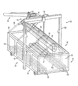
Figure 1 is a side view of an example of an overhead material handling system
in a
raised position as an open-top container is being deposited from a roll-off
container truck;
Figure 2 is a side view of the overhead material handling system of Figure 1
with
the leveler in place on and parallel to the container;
Figure 3 is a top view of the overhead material handling system of Figure 1
with
the leveler in place on and parallel to the container;
Figure 4 is a cross-sectional side view of the overhead material handling
system of
Figure 1 with expelled compacted material within the trough;
Figure 5A is a detail cross-sectional side view of expelled compacted material
within the trough of the material handling system of Figure 1;
Figure 5B is a detail cross-sectional side view of Figure 5A showing the
trigger of
the material handling system of Figure 1;
Figure 6 is an isometric view of the overhead material handling system of
Figure 1
with expelled compacted material in the form of a plurality of continuous logs
discharged
in the container; and
Figure 7 is a cross-sectional end view of the overhead material handling
system of
Figure 1 showing the cover in the form of a frustum along its length in this
embodiment.
4
CA 02827743 2013-09-16
DETAILED DESCRIPTION
In the following detailed description, reference is made to the accompanying
figures, which form a part hereof. In the figures, similar symbols typically
identify similar
components, unless context dictates otherwise. The illustrative embodiments
described in
the detailed description, figures, and claims are not meant to be limiting.
Other
embodiments may be utilized, and other changes may be made, without departing
from the
scope of the subject matter presented herein. It will be readily understood
that the aspects
of the present disclosure, as generally described herein, and illustrated in
the figures, can
be arranged, substituted, combined, separated, and designed in a wide variety
of different
configurations, all of which are explicitly contemplated herein.
In a first aspect, as shown in Figures 1-7, an exemplary overhead material
handling
system 10 is provided. The overhead material handling system comprises: (a) a
compactor
17 and (b) a leveler 20 that comprises (i) a cover 25, (ii) a trough 30, and
(iii) a trigger 35,
where the trough 30 has a first end 31 and a second end 32 and the trough 30
is rotatably-
mounted between a first end 26 of the cover 25 and a second end 27 of the
cover 25.
As used herein, an "overhead material handling system" 10 is designed to be
used
with any type of material capable of being washed, dewatered and compacted.
For
example, the material may be any flowable (e.g., loose) material. In some
examples, the
material may be scrap pieces. In other examples, the material may be a
biomaterial such
as sludge or dirt. In other examples, the material may comprise wastewater
screenings.
Still other flowable materials may be used with the overhead material handling
system 10.
As used herein, a "compactor" 17 comprises (i) an inlet 65, (ii) a housing 70,
(iii)
motorized compacting means for moving, compacting and dewatering materials
within the
housing, and (iv) an outlet 75. In some embodiments, a water discharge conduit
may be
coupled to the housing 70. The housing 70 receives material through its inlet
65 and
advances that material through the body of the housing 70 via a compactor
screw in
communication with a pressing section or a conical or pinch valve (not shown).
In some
embodiments, the pressing section or the conical or pinch valve form a solid
plug in a
compression zone by reducing the cross-section of housing 70. This increases
back
pressure on the material in the housing 70 to force entrained water from the
solids and out
additional perforations or slots to achieve desired compaction of the
material. A drive unit
80 includes a motor and gear reducer in communication with the compactor screw
generate the necessary force to advance the materials through the housing 70.
The horse
CA 02827743 2013-09-16
power of the motor may vary depending on the type of materials required to be
washed
and/or compacted and ultimately advanced through the overhead material
handling system
10.
As the compactor 17 compresses the material, water is optionally drained in a
dewatering zone (not shown) and then out through the water discharge conduit.
The
compacted material is condensed by the pressing section or the conical or
pinch valve
preferably such that the compacted material would pass the Paint Filter
Liquids Test
Method 9095B issued by the EPA. The compacted material is then advanced
through the
outlet 75 and into the leveler 20.
In some embodiments, the overhead material handling system 10 may compact and
advance materials without a washing cycle. In other embodiments, the overhead
material
handling system 10 employs a washer compactor 15. As used herein, a "washer
compactor" 15 washes, dewaters and compacts material or screenings. The washer
compacter 15 comprises a washer 16 and the compactor 17, described above, that
may be
arranged linearly, shown in Figures 1-4 and 6, or in stacked arrangement (not
shown) such
that the washer 16 is disposed above the compactor 17.
As used herein, a "washer" (again if we do not use washer can we just say
compactor) 16 comprises (i) a tank 40 (not needed if not washer), (ii) a screw
45, (iii) a
drive unit 80, (iv) at least one spray nozzle 50, (v) a water discharge
conduit 55, and (vi) a
material discharge outlet 60. The tank 40 defines a bottom surface and
sidewalls and is
sized to receive screenings. The tank 40 may range from about 6 inches to 48
inches in
height, about 12 inches to 36 inches in width, and about 12 inches to 36
inches in length,
and is preferably about 12 inches to 24 inches in height, about 12 inches to
18 inches in
width, and about 24 inches to 36 inches in length. Further, in one embodiment,
a feeding
conveyor system 85 for material transport is in communication with the washer
16. The
feeding conveyor system 85 may include a number of types of conveyors or
feeder pipes
and drive units known in the art to move any of the material types discussed
herein. The
feeding conveyor system 85 may continuously drop material or screenings into
the open
tank 40 from above.
The screw 45 is disposed within the tank 40 and may be shaft-mounted or
shaftless.
If the screw 45 is shaft-mounted, bearings may be utilized at each end of the
shaft. The
screw 45 is a spiral flange, preferably in the range from 4 inches to 16
inches in diameter,
adapted to move material in a particular direction through the tank 40 as the
screw 45 is
6
CA 02827743 2013-09-16
rotated by the drive-unit 80. The drive unit 80 is coupled to the screw 45 and
has a motor
and drive mounted to one end of the tank 40. In another embodiment, the drive
unit 80
may be coupled directly to the compactor screw. In operation, the screw 45
agitates and
advances material forward towards the material discharge outlet 60, but may
also operate
in reverse if the material backs-up.
At least one spray nozzle 50 directs water into the tank 40 to wash the
material
being advanced by the screw 45. In one example embodiment, shown in Figures 1-
4 and 6,
a single spray nozzle 50 is employed at the end of the tank 40 that is coupled
to the
material discharge outlet 60. In another example embodiment, a plurality of
spray nozzles
50 are spaced apart along the length of the tank 40. In each embodiment, the
at least one
spray nozzle 50 emits wash water at a pressure ranging from about 20 psi to 80
psi to
ensure fecal matter and other organic material, for example, is adequately
separated from
the screenings.
The wash water and rinsed-off organics drain out through the water discharge
conduit 55. Draining the wash water is the first part of the dewatering
process that the
material will undergo. The water discharge conduit 55 is coupled to the bottom
surface of
the tank 40, though in some embodiments it may be connected to one of the
sidewalls of
the tank 40, preferably at the end of the tank 40 coupled to the material
discharge outlet 60
shown in Figure 3.
In one embodiment, a graduated filtering system is employed in the tank 40 to
prevent the material or screenings from clogging or blocking the water
discharge conduit
55. This graduated filtering system may include (a) a first filter or screen
defining a first
set of holes or pores that is disposed immediately under the screw 45, (b) a
second filter or
screen defining a second set of holes or pores that are smaller than the first
set of holes,
where the second filter is disposed below and spaced apart from the first
filter, and (c) a
third filter or screen defining a third set of holes or pores that are smaller
than the second
set of holes, where the third filter is disposed directly over the water
discharge conduit 55.
The first, second and third sets of holes may range from about 1 mm to 6mm. In
an
alternative embodiment, a single filter or screen may be disposed directly
over the water
discharge conduit 55, and the holes may range from about 1 mm to 3 mm.
In another embodiment, the washer 16 has a free draining zone with
perforations or
slots located directly under the material discharge outlet 60. The free
draining zone can be
cleaned by the scouring action of the screw 45 passing over the perforations
or slots. In
7
CA 02827743 2013-09-16
some embodiments, a brush is fastened to the screw 45 in the free draining
zone to aid in
the scouring action.
The material discharge outlet 60 is defined at one end of the tank 40. The
rotating
screw 45 of the washer portion 16 transfers the substantially drained material
or screenings
from the tank 40 through the material discharge outlet 60, which is coupled to
the
compactor's inlet 65.
As used herein, a "leveler" 20 comprises (i) a cover 25, (ii) a trough 30, and
(iii) a
trigger 35. As shown in Figure 6, the cover 25 comprises four sidewalls 28 and
a top
surface 29 that is coupled to each sidewall 28. The cover 25 further has a
first end 26 and
a second end 27. The top surface 29 of the cover 25 may be flat (see Fig. 1),
peaked,
domed, or may bear the cross-section of a frustum along its length from the
first end 26 to
the second end 27 (see Fig. 6), for example. The first end 26 of the cover 25
also defines
at least one input 24 through which the material may be transferred to the
trough 30. The
input 24 may be an opening, orifice, port, or open chute in the cover 25. The
material may
be deposited into the input 24 from the compactor portion's outlet 75.
In some example embodiments, the cover 25 may comprise a fabric coated in
polyvinyl chloride (pvc). In other embodiments, the cover 25 may be made from
steel,
such as a stainless steel. Other materials for the cover 25 are also possible.
The cover 25
allows for pest and odor control and prevents the exposure of material within
the container
90 to the exterior environment. The cover 25 also serves as a barrier from the
afore-
mentioned exposure, thus increasing the safety of the personnel operating the
overhead
material handling system 10.
The cover 25 may further define inspection ports and material level sensor
(not
shown) in one or both of the top surface 29 or sidewalls 28 to aid in the
placement of the
leveler 20 on the container 90 or to inspect a mechanical failure and/or the
contents of the
container 90. These inspection ports may comprise slideable panels, hinge-
mounted doors,
or inlets made of clear plastic, such as Plexiglass. In some examples, the
input 24 may
serve as both an inspection port and as an opening through which material 95
can be fed.
The trough 30 is a traditional U-shaped trough made from a rigid material, for
example carbon or stainless steel, aluminum or polymeric material. The trough
30 may be
reinforced along its length with ribs 33 disposed on the trough's exterior to
prevent
twisting along its length. The trough 30 has a first end 31 and a second end
32 and is
rotatably-mounted between corresponding first and second ends 26, 27 of the
cover 25. In
8
CA 02827743 2013-09-16
one embodiment, the trough's first end 26 is connected to a shaft and bearing
or to a
rotating coupling, while the trough's second end 27 is mounted to a drive
shaft. The drive
shaft in turn is coupled to shafted gear reducer and motor. The shafted gear
reducer and
motor impart torque to the trough 30 causing it to rotate in one of a first or
a second
direction. Alternatively, hydraulic pistons or electric actuators may be used,
for example,
to cause rotation of the trough 30.
In another embodiment, the base of the trough 30 is mounted on a shaft having
first
and second ends. Here, the first and second ends of the shaft may be
optionally mounted
within roller bearings.
In another embodiment (not shown), the first end 31 and second end 32 of the
trough 30 are each coupled to two guide posts. These guide posts are located
at opposing
sides of the top of the U-Shaped cross-section and extend longitudinally
beyond the first
and second ends 31, 32 of the trough 30. Here, the first end 26 and the second
end 27 of
the cover 25 each define a guiding channel that is arc shaped or substantially
circular to
mimic the path of rotation of the trough 30. The two guideposts at the first
end 31 of the
trough 30 are disposed within the guiding channel defined in the first end 26
of the cover
25, while the two guideposts at the second end 32 of the trough 30 are
disposed within the
guiding channel defined in the second end 27 of the cover 25. The guideposts
and guiding
channels stabilize the ends of the trough 31, 32 to help prevent the trough 30
from twisting
along its length when torque is applied by the drive shaft or other
translation means, for
example, hydraulic pistons or electric actuators. The shaft and guide post
embodiments
may be used in combination or in isolation. In the embodiment in which the
guideposts
are used in isolation, the drive shaft is coupled to at least one of the
guideposts at the
second end 32 of the trough 30.
The trigger 35 is used to sense the presence of expelled compacted material 95
at
or near the second end 32 of the trough 30 and to trigger rotation of the
trough 30 in one of
a first or a second direction towards the respective sidewalls 91, 92 of the
container 90. In
one embodiment shown in Figures 5A and 5B, the trigger 35 includes a moveable
plunger
35, wherein the trigger 35 is axially mounted within the trough 30 at the
second end 32
and is biased by a spring in the direction of the first end 31. While the
trigger 35 is
preferably axially mounted, it may be off-center from the trough's axis, as
long as the
trigger 35 is disposed in the path of the expelled compacted material. In this
embodiment,
the plunger trigger 35 is axially displaced a distance, preferably in the
range of about 1/4
9
CA 02827743 2013-09-16
inch to sixes inches, by the expelled compacted material 95 toward the second
end 27 of
the cover 25 until the plunger trigger 35 engages an electrical or mechanical
switch, for
example by completing an electrical circuit or by releasing a spring-loaded
drive
mechanism. When the switch is engaged, the trough 30 rotates from an upright
position
about its base toward one of the sidewalls 91, 92 of the container 90 to
unload the expelled
compacted material 95 into the container 90. The trough 30 then returns to its
upright
position.
Directional rotation of the trough may be directed by a counter relay in a
computer
operated electronic control panel. The counter relay counts
clockwise/counterclockwise
rotation in one of the first and second directions and sends a signal to a
reversing motor
starter to return the trough 30 to its upright position.
In another embodiment, the leveler 20 may further comprise a counterweight
that
extends along a longitudinal length of the base of the trough 30. When the
trough 30 has
moved from its upright position to its discharge position, the counterweight
is raised in the
air and gravity then causes the counterweight to fall, bringing the trough 30
back to the
upright position.
In an alternative embodiment (not shown), the trigger 35 comprises a sensor
disposed at the second end 32 of the trough 30. The sensor may comprise a
proximity
sensor able to detect the presence of nearby objects without any physical
contact, such as
an optical sensor, a light sensor, or an imaging sensor, for example. The
proximity sensor
may be disposed within the trough 30 or may be alternatively coupled to the
top surface 29
of the cover 25. The sensor alternatively may be of a type that requires
direct contact with
the expelled compacted material 95, such as a pressure sensor or a load cell,
disposed on
the base of the trough 30. When this direct-contact sensor is triggered it
sends an
electrical signal to the switch, as discussed above, to cause the rotation of
the trough 30 to
discharge the expelled compacted material 95 into the container 90.
In one embodiment, the overhead material handling system 10 includes a support
structure 100 pivotally supporting the cover 25 and configured to move the
leveler 20
between a raised position and a lowered position, that positions the leveler
20 substantially
parallel to the container 90. The support structure 100 is positioned a
distance away from
the first end 26 of the cover 25, and in some examples may be positioned near
the second
end 27 of the cover 25. The support structure 100 includes a support frame 105
and an
attachment mechanism 110 for removable attachment to the cover 25. The
attachment
CA 02827743 2013-09-16
mechanism 110 may include at least one chain hoist or pull-cord that is
attachable to at
least one eyebolt or other attachment mechanism on the top surface 29 of the
cover 25. In
some examples, the support frame 100 may include a framework of beams, posts,
and
corner braces.
In one embodiment, the overhead material handling system 10 includes at least
one
mechanical lifting mechanism 115 coupled to the cover 25. The mechanical
lifting system
may include a hydraulic system. The hydraulic system may include hydraulic
pistons that
are coupled to the first end 26 of the cover 25 and are configured to pivot
the cover 25
about the first end 26. In operation, the cover 25 pivots upwards about the
axis at the first
end 26, such that the second end 27 is positioned higher than the first end
26. In this
position, the second end 27 is further away from the container 90, allowing
the container
90 to be tilted upwards for placement onto the truck 120. The support
structure may
further include a cover guide designed to prevent the cover from moving side
to side,
which can damage the pivot attachment. A beam structure supports the hydraulic
system
and positions the hydraulic system so that it can be properly coupled to the
cover 25 to
enable for the pivoting movement of the cover 25. A computing system may
execute
instructions to cause the hydraulic system to pivot the cover 25.
Alternatively, an operator
or other personnel may direct the power of the hydraulic system to pivot the
cover 25.
The hydraulic system may pivot the cover 25 along the various axes to position
the cover
25 in a number of different locations. In some examples, sensors may be
positioned on the
cover 25 to aid in the detection and determination of the position and
movement of the
cover 25. In some example embodiments, ultrasonic sensors may be used as level
indicating devices to detect and determine the position of the cover 25. In
some examples,
a shutoff switch may also be included. The shutoff switch may be located under
the cover
to sense that a cover has been separated from the container and subsequently
halt all
mechanical operations and alert a system operator of the issue.
In another embodiment, the mechanical lifting mechanism 115 could comprise
floor jacking screws. In still another embodiment, the mechanical lifting
mechanism 115
could raise the cover vertically through an attachment mechanism coupled to
the four
corners of the cover.
As used herein, a "container" 90 may be any open-top container, and may
include
wheels and a hitch at either end to facilitate transportation on and off of
the roll-off
container truck 120 or another vehicle. The container 90 may include sidewalls
and a
11
CA 02827743 2013-09-16
bottom that define an interior, wherein the interior is an upwardly open
space. The
container 110 preferably includes wheels attached to the bottom.
The roll-off container truck 120 may be any standard roll-off container truck
known in the art. In an alternative example, the truck may comprise a vehicle
towing a
bed on which the container 90 may be loaded. Still other alternative examples
may be
envisioned.
In one embodiment, the overhead material handling system 10 includes a vent
system 125 and an air filtration system in communication with the vent system
125. The
combination of the vent system 125 and the air filtration system is configured
to reduce
odor buildup from within the container 90. The vent system 125 is shown
coupled to the
cover 25. The air filtration system is coupled to the vent system 125 and may
include odor
control features commonly used in the art. For example, scrubbers may be used
that pull
odor from various locations and "scrub" the odor by forcing air through a
vessel
containing different media to eliminate or mitigate odorous air build up
within the
container 90. Air filtration system could be carbon based, filter based or
biological based.
In another embodiment, the handling system 10 may further include a guide rail
and a stopping plate for ease of positioning the container 90 under the cover
25.
In a second aspect, a method is provided for loading and evenly distributing
material into a container 90 using the overhead material handling system 10
described
with reference to Figures 1-7, where the method comprises: (a) moving,
compacting and
dewatering material in the compactor 17, (b) expelling compacted material 95
into the
first end 31 of the trough 30, (c) driving expelled compacted material 95
along the length
of the trough 30 toward the second end 32 of the trough 30, (d) activating the
trigger 35,
(e) rotating the trough 30 in a first direction from an upright position
toward a first side 93
of a container 90, (f) emptying the material 95 from the trough 30 into the
first side 93 of
the container 90, (g) returning the trough 30 to the upright position, (h)
repeating steps (a)
to (d), (i) rotating the trough 30 in a second direction from the upright
position toward a
second side 94 of the container 90, and (j) emptying the material 95 from the
trough 30
into the second side 94 of the container 90.
In practice, discharging the compacted material into the container 90 in a
rotating
side-to-side manner allows the compacted material to be evenly distributed and
loaded in
an efficient manner. Further, the rotating mechanism could be programmed to
discharge
the material a certain number of times to the first side of the container 90
and then a
12
CA 02827743 2013-09-16
certain number of times to the second side of the container 90 to achieve a
full layer of
material on the bottom of the container 90. The process is then repeated to
achieve the
next layer, and so on until the container 90 is filled to a desired level.
In one embodiment, driving the expelled compacted material 95 along the length
of
the trough 30 toward the second end 32 of the trough 30 comprises continuously
expelling
compacted material 95 into the first end 31 of the trough 30 such that the
compacted
material 95 is forced along a base of the trough 30.
In a preferred embodiment, the expelled compacted material 95 is in the form
of a
substantially continuous log 130. The log 130 is preferably circular in cross-
section, but
any polygonal cross-section is contemplated, as long as the shape does not
impede the log
130 from rolling along the base of the container 90 or along the top surface
131 of a
plurality of previously expelled logs 130 (see Figures 6-7).
In a preferred embodiment, after the material 95 has been emptied from the
trough
30, the method further provides rolling the expelled material along one of a
base of the
container 90 or a top surface 131 of previously expelled compacted logs 130
until the
expelled material reaches one of the first side 93 of the container 90, the
second side 94 of
the container 90, or a side of a previously expelled compacted log 132.
In a preferred embodiment, activating the trigger 35 comprises applying a
force to
a plunger 35 via the expelled compacted material 95. In an alternative
embodiment,
activating the trigger 35 comprises sensing the expelled compacted material
via a sensor of
a type discussed above with respect to the overhead material handling system
10 described
in connection with Figures 1-7.
In operation, the steps of the method are repeated until the container is
substantially full. When the container 90 is filled with the desired amount of
material 95
or to capacity (this can be determined by using the inspection ports
previously discussed,
by using sensor technology or other alternative means), the flow of expelled
compacted
material 95 is stopped and the cover 25 is lifted using either the mechanical
lifting
mechanism 115, the support structure 110, or both, and the container 90 is
moved onto a
bed of a truck 120 or other vehicle. Another container may then be placed
under the
overhead material handling system 10, and the cover 25 may be lowered to
position the
handling system 10 to again deposit material into the container. Further,
multiple levelers
and containers may work in series or parallel in instances in which solid
material is highly
concentrated or there is a lack of operator availability, for example. In
operation, a sensor
13
CA 02827743 2013-09-16
or weigh cell may determine that a particular container is full and sends a
signal for a feed
discharge gate to close while opening another feed discharge gate to allow
materials to
move forward to the next container(s) until full containers can replaced with
empty
containers.
It should be understood that arrangements described herein are for purposes of
example only. As such, those skilled in the art will appreciate that other
arrangements and
other elements (e.g. machines, interfaces, functions, orders, and groupings of
functions,
etc.) can be used instead, and some elements may be omitted altogether
according to the
desired results.
While various aspects and embodiments have been disclosed herein, other
aspects
and embodiments will be apparent to those skilled in the art. The various
aspects and
embodiments disclosed herein are for purposes of illustration and are not
intended to be
limiting, with the true scope being indicated by the following claims, along
with the full
scope of equivalents to which such claims are entitled. It is also to be
understood that the
terminology used herein is for the purpose of describing particular
embodiments only, and
is not intended to be limiting.
14