Note: Descriptions are shown in the official language in which they were submitted.
= CA 02827785 2013-08-20
BEARING ARRANGEMENT COMPRISING A BACKUP BEARING
Description
Field of the invention
The invention relates to a bearing arrangement for mounting a shaft on a
connection structure,
wherein the bearing arrangement comprises a backup bearing according to the
preamble of
claim 1.
A bearing arrangement for mounting a shaft on a connection structure is known
from practice,
as is the use of a backup bearing, wherein the backup bearing comprises a
bearing ring,
wherein the bearing ring of the backup bearing forms a backup bearing
clearance with the
shaft during normal function of the bearing, and contacts the shaft in a
loaded state, namely
during failure of the bearing. A housing with the bearing and the backup
bearing is then
mounted in the hole of a bearing seat on a connection structure. If the
bearing, for example a
magnetic bearing, fails, then a loaded state occurs, the bearing ring of the
backup bearing,
which in normal operation of the bearing maintains the backup bearing
clearance to the shaft,
contacts the quickly rotating shaft, wherein high forces arise in the backup
bearing, which
forces concentrate on one very small section of the circumference of the
bearing ring of the
backup bearing. In this area, rolling elements or the race of the bearing ring
of the backup
bearing can be damaged.
EP 1 395 759 B1 describes a bearing arrangement for mounting a shaft at a
housing
comprising a magnetic bearing mounting the shaft and a backup bearing,
wherein, in normal
operation of the magnetic bearing, the bearing ring of the backup bearing
maintains a backup
bearing clearance to the shaft. If the magnetic bearing fails, the shaft falls
into an inner ring of
the backup bearing. To prevent high axial and radial forces, a first
intermediate element is
mounted on the housing and a second intermediate element is mounted on an
outer ring of the
backup bearing, wherein the second intermediate element has a radial groove in
which a radial
CA 02827785 2013-08-20
2
lug on the first intermediate element engages. Damping elements are provided
between the lug
and the groove, which damping elements should suppress a transfer of force
from the backup
bearing to the rigid housing.
Object of the invention
It is the object of the invention to provide a bearing arrangement with a
backup bearing, in
which the forces arising in the backup bearing in the loaded state can be
better absorbed.
Summary of the invention
This problem is inventively solved for the bearing arrangement listed at the
beginning in that a
slit designed as an opening is provided extending substantially in the
peripheral direction.
The opening extends substantially in the peripheral direction, such that a
curved slit is
designed. The opening is for example guided substantially parallel to the axis
of the bearing
between axially separated end surfaces of the housing.
The opening effects a material weakening, so that the shaft falling into the
backup bearing
causes an elastic yielding of the material of the housing between the opening
of the curved slit
and the bearing ring of the backup bearing. The bearing ring of the backup
ring falling into the
housing is thereby locally caught in the area of the slit, elastically
absorbed in the loaded state.
In particular, said surface section increases in the peripheral direction of
the bearing ring of
the backup bearing, which bearing ring takes up the weight of the shaft, such
that the weight
of the shaft falling into the backup bearing is distributed across an
increased surface area of
the bearing ring of the backup bearing, by which means localized peak loads of
the backup
bearing are suppressed. The opening, which extends only sectionally in the
peripheral
direction, reduces in particular the rigidity of the bearing arrangement in a
targeted way.
CA 02827785 2013-08-20
3
Due to the elastic yielding of the material of the housing between the opening
and the shaft in
the loaded state, a so-called backward whirl can also be suppressed, thus a
creep of the shaft
along the bearing ring of the backup bearing facing the shaft, during which
the shaft runs
along the inner lateral surface of the inner bearing ring at high rotational
speed. During this
running of the shaft along the inner lateral surface, the bearing ring of the
backup bearing
facing the shaft can undergo a high acceleration, such that high forces and
even a slippage can
occur in the backup bearing, which could respectively damage the backup
bearing.
It is preferably provided that the opening of the slit is produced by wire
electric discharge
machining, laser cutting, or water jet cutting, so that the opening can be
designed as an
opening extending linearly of very narrow gap width. The gap width of the slit
is thereby
typically less than approximately 2.0 millimeter, for example only
approximately 0.25
millimeter, and corresponds substantially to the amount of the deflection of
the backup
bearing to the shaft in the housing in the loaded state.
It is preferably provided that the backup bearing has a load direction, and
that the opening
extends substantially symmetrically to the load direction. The load direction
corresponds for
example with the direction of gravity. If two or more load directions can be
assumed, then
more than one opening can be provided, in particular an opening for each load
direction
respectively, wherein the openings are arranged along the periphery as well as
radially offset
relative to the rotational axis of the shaft.
It is preferably provided that the section-like opening provided extends over
a circumferential
angle of approximately 50 to approximately 180 , particularly approximately
120 . Based on
the larger circumferential angle, the force in the loaded state is distributed
on several rolling
elements or on a larger peripheral section of the bearing ring of the backup
bearing, wherein
forces of the loaded state assumed to be particularly high are received by an
opening
extending over a large circumferential angle.
CA 02827785 2013-08-20
4
It is preferably provided that the opening has a substantially constant
distance from the
rotational axis of the bearing ring of the backup bearing, wherein the opening
is designed as
an arc of a circle. It should, however, be understood that other courses of
the opening in the
peripheral direction could be provided, such that the opening can be designed
for example as a
polyline or as a sine wave, when viewed from a top view at the bearing
arrangement in the
direction of the rotational axis of the shaft.
It is preferably provided that, in an overload state, the walls of the opening
abut each other. By
this means, the maximum possible elastic deformation is exploited, however, at
the same time
a damaging ductile deformation of the housing is prevented. An overload state
is thereby to be
understood as a loaded state, during which an exceptionally high excessive
shock occurs.
It is preferably provided that a gap width of the opening of the slit
increases at least at one end
section of the opening. By increasing the gap width of the slit, notch
stresses emerging at the
ends of the slit can be prevented, which notch stresses could damage the
housing in the loaded
state.
It is preferably provided that the opening is curved away from the shaft at
least at one end
section. The curving of the slit likewise effects a suppression of notch
stresses in the loaded
state.
Additional advantages and features arise from the dependent claims as well as
from the
following description of a preferred embodiment of the invention.
The invention will be subsequently described and explained in more detail with
reference to
the attached drawings.
=,, . CA 02827785 2013-08-20
Short description of the drawings
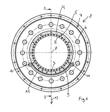
Figure 1 shows a top view of a housing which is part of an
embodiment of an
inventive bearing arrangement,
5 Figure 2 shows a section of a cutout view of the housing from
figure 1 along the
line `A-A' in figure 1, and
Figure 3 shows the section 'A' from figure 2 in an enlarged
depiction.
Detailed description of the figures
Figure 1 shows a top view of a housing 1 which is part of a bearing
arrangement for rotatable
mounting of a shaft (not depicted) at a connection structure (not depicted).
An outer surface of
the housing 1 is thereby mounted in a hole of a bearing seat. The shaft is
rotatably mounted
with respect to the housing 1 as well as to the connection structure by means
of a bearing, in
particular by means of a magnetic bearing (not shown).
The bearing arrangement further comprises a backup bearing (not depicted),
which is designed
as a roller bearing, the inner ring thereof being mounted on the shaft, and
the outer ring
thereof maintaining a backup clearance to an inner surface of the housing 1 as
long as the
mounting of the shaft is secured by the magnetic bearing. If the magnetic
bearing fails, thus a
loaded state occurs, the shaft falls due to the weight thereof into the backup
bearing, such that
the backup bearing with the outer ring is pressed on to an inner surface 15 of
the housing 1
(figures 2, 3), which housing supports the shaft in this case at least for a
short time.
The substantially circular housing 1 has a rear section 2 which is arranged
below the plane of
the paper, wherein a circumferential sequence of blind holes is provided in
the rear section 2,
one of which blind holes is provided with the reference '3'. Springs are
mounted in the blind
holes 3, which springs impinge the outer ring of the backup bearing axially,
thus in a direction
perpendicular to the plane of the paper, so that the backup bearing, which is
designed as a
double row angular ball bearing with common inner ring for two races of the
ball-shaped
CA 02827785 2013-08-20
6
roller elements, is mechanically pretensioned. The housing 1 has a front
section 4 located
above the plane of the paper, in which front section a likewise
circumferential sequence of
holes is provided, one of which holes is designated with the reference '5',
wherein the holes 5
are designed for mounting a cover. In the area of the front section 4, a
circumferential
sequence of ventilation holes is additionally provided, one of which
ventilation holes is
designated with the reference '6', as well as mounting holes for mounting the
housing 1 on the
connection structure, wherein one of the mounting holes is designated with the
reference '7'.
The circumferential sequence of holes 5, ventilation holes 6, mounting holes 7
of the front
section 4 as well as the blind holes 3 of the rear section 2 of the housing 1
are respectively
aligned concentrically to an axis of symmetry 8, wherein the axis of symmetry
8 corresponds
to the rotational axis of the shaft during normal, uninterrupted operation of
the magnetic
bearing as well as the rotational axis of the backup bearing.
A slit 9 is provided in the body of the housing 1, which slit 9 extends only
sectionally in the
peripheral direction of the circular housing 1 and is designed as an opening,
wherein the
opening is guided parallel to the axis 8, thus also parallel to the rotational
axis of the magnetic
bearing or of the backup bearing and thus perpendicular to the plane of the
paper in figure 1.
The slit 9 extends over a third of a circle, thus across a circumferential
angle of 120 , wherein
the opening of the slit 9 is produced by wire electric discharge machining
(alternatives to this
are for example laser cutting, or water jet cutting). The circumferential
angle of slit 9 could
also assume other values, for example a value between approximately 50 and
approximately
180 .
The slit 9 has two end sections 10, 11, at which end sections a gap width of
the opening, thus
the distance between the opposite sides of the opening, increases. The gap
width of the slit 9 is
approximately 0.2 millimeters across a length of approximately 95% of the
extension in the
peripheral direction and distinctly increases at the end sections 10, 11. Due
to the very low
gap width of approximately 0.2 millimeters, in an overload state, thus a
loaded state with an
CA 02827785 2013-08-20
7
exceptionally high excessive shock, the walls of the opening of the slit 9
abut each other and
thus the slit 9 lies on the block. During the production of the opening of
slit 9, for example by
means of wire electric discharge machining, the steel wire performing the
machining at the
end sections 10, 11 is guided back in an arc to the already created slit
section, so that a
virtually cylindrical material piece with a substantially drop-shaped cross
section is separated
from the body of the housing 1. It should be understood that one of the two
end sections 10,
11 can be prepared as the insertion hole for the wire, for example, as a hole
into which the
wire for the wire electric discharge machining is guided. It is further
understood that the wire
for implementing the electric discharge machining can be guided back only
incompletely,
such that there results a curved gap only a little broader at the end sections
pointing away from
the axis 8.
The opening of the slit 9 is designed within a recess 12 so that the material
removal during the
formation of the opening is reduced.
The bearing arrangement with the backup bearing and the housing 1 has a
preferred load
direction which is given by the direction of gravity affecting the shaft and
in the depiction of
figure 1 functions in the direction of line A-A in the direction of arrow 13.
The slit 9 with the
opening is designed symmetrically relative to this load direction 13.
The opening of the slit 9 has a constant distance from the rotational axis 8
of the bearing ring
of the backup bearing in normal operation of the magnetic bearing such that
the slit 9 is
designed with the opening as an arc.
Figure 2 and figure 3 respectively show the housing 1 from figure 1 as a cross
section in a
view along the line A-A. The opening of the slit 9 is executed from the floor
14 of the recess
12 to a floor of a recess on the axially opposite side of the housing 1
relative to the axis 8 and
is guided parallel to the axis 8 as well as perpendicular to the load
direction 13.
-
CA 02827785 2013-08-20
8
In the previously described embodiment, the opposite walls of the opening of
the slit 9 abut
each other in an overload state relative to the axis 8. It is understood that
a filler material can
be provided in the opening, for example a bendable film, which reduces the gap
width of the
slit or fills in the intermediate space between the opposing walls, or a
fluid, which fills up the
gap of the slit, wherein the filler material absorbs the forces arising in the
loaded state.
It was assumed in the previously described embodiment that the backup bearing
clearance
between the outer ring of the roller bearing and the inner surface of the
housing 1 is
substantially open. It is understood that a wave spring can be arranged
between the bearing
ring of the backup bearing and the housing 1, which wave spring at least
partially absorbs the
forces arising in a loaded state and distributes them across a larger surface
area of the housing.
In the previously described embodiment, the opening of the slit 9 is designed,
in the end
sections 10, 11 as well, as an arc. It is understood that, in the end sections
10, 11, the slit can
have a curve pointing away from the shaft or the axis 8 or can even deviate
from the arc
contour.
Departing from the previously described embodiment, the slit can also have a
course deviating
from the arc in the peripheral direction of the housing 1, for example, the
distance to the axis 8
can vary periodically in the peripheral direction so that the slit has for
example a sine-shaped
course. As another alternative to a periodic course in the peripheral
direction, the slit can be
designed as a polyfine.
=
CA 02827785 2013-08-20
9
References
1 Housing
2 Rear section of the housing 1
3 Blind hole
4 Front section of the housing 1
5 Hole
6 Ventilation hole
7 Mounting hole
8 Axis
9 Slit
10 End section
11 End section
12 Recess
13 Load direction (arrow)
14 Floor
15 Inner surface of the housing 1