Note: Descriptions are shown in the official language in which they were submitted.
CA 02827813 2013-08-20
WO 2012/114326 PCT/IL2012/000025
CUTTING TOOL AND CUTTING INSERT HAVING CLAMPING RECESS
THEREFOR
FIELD OF THE INVENTION
[001] The subject matter of the present application relates to turning
tools, and rotary
slotting cutters.
BACKGROUND OF THE INVENTION
[002] Turning tools, having a cutting insert clamped in an insert pocket
are disclosed, for
example in EP 0559965B1.
[003] It is an object of the subject matter of the present application to
provide a new and
improved cutting tool.
SUMMARY OF THE INVENTION
[004] In accordance with the subject matter of the present application there
is provided a
cutting insert comprising:
opposing insert front and rear ends,
opposing first and second major surfaces and two side surfaces extending
therebetween,
two side abutment surfaces, each located on a respective side surface,
an insert front surface formed at the insert front end and extending between
the first
and second major surfaces and between the side surfaces, and
a clamping recess opening out to the second major surface and/or to the insert
front
surface;
the side abutment surfaces converging towards the first major surface, the
side
surfaces converging in a direction away from the insert front surface and the
first surface
merging with the front surface and the side surfaces at an edge, at least a
portion of which
comprising a cutting edge,
wherein
the clamping recess comprises an insert clamping surface which faces towards
the
insert front end, and wherein the clamping recess does not extend beyond a mid
plane P,
- 1-
CA 02827813 2013-08-20
WO 2012/114326 PCT/IL2012/000025
which is located midway between the first and second surfaces in a thickness
direction of the
cutting insert.
In accordance with the subject matter of the present application there is
further
provided a holder comprising:
an insert pocket comprising:
an insert pocket front end and an insert pocket rear end;
an insert pocket front surface located at the front end of the insert
pocket;
an insert support surface extending from the insert pocket front surface,
to in a rearward direction, towards the insert pocket rear end;
two support walls extending from the insert support surface to an insert
pocket top surface, in an upward direction, away from the insert support
surface, the support walls converging in the upward direction, and in the
rearward direction;
a housing opening out to the insert support surface and to the insert
pocket front surface, the housing comprising a housing wall extending
downwards from the insert support surface and a housing peripheral surface
extending from the housing wall to the insert pocket front surface; and
a bore opening out to the housing wall, the bore having a longitudinal
bore axis B; and
a clamping member comprising a head with a head clamping surface,
wherein
when the clamping member is located in the housing, an exposed clamping
surface of
the head clamping surface protrudes above the insert support surface.
[005] In accordance with the subject matter of the present application
there is still further
provided a cutting tool comprising the holder and the cutting insert, securely
clamped in the
insert pocket of the holder.
[006] In an assembled position of the cutting tool:
the second major surface abuts the insert support surface;
each side abutment surface abuts a respective support wall;
an exposed head portion of the head is accommodated by the clamping recess;
and
the exposed clamping surface of the head clamping surface abuts the insert
clamping
surface.
- 2 -
CA 02827813 2013-08-20
WO 2012/114326 PCT/IL2012/000025
[007] It is understood that the above-said is a summary, and that any of the
aspects above
can further comprise, or be further defined with, any of the features
described in connection
with any of the other aspects or features described hereinbelow. For example,
the following
features may be applicable to any of the above aspects of the invention:
[008] The clamping recess can open out to the second major surface and/or to
the insert
front surface at a non-round opening.
[009] The opening can have a rectangular shape.
[0010] In a direction perpendicular to the mid plane P, the insert clamping
surface has a
length L and the cutting insert has a maximum thickness T; and wherein the
length L can be
in the range of 10% to 45% of a maximum thickness T of the cutting insert.
[0011] The cutting insert can be devoid of through holes.
[0012] In a cross sectional front view of the cutting insert, the clamping
recess can have an
arched shape.
[0013] The insert clamping surface can be perpendicular to the second major
surface.
[0014] The clamping recess can comprise an insert abutment surface located
opposite the
insert clamping surface.
[0015] The insert pocket can be configured only for clamping cutting inserts.
[0016] The clamping member can be a screw.
[0017] The longitudinal bore axis B can be parallel to the insert support
surface.
[0018] The housing peripheral surface can comprise a plurality of rail-shaped
head support
surfaces which extend along its length.
[0019] The holder can comprise a washer, located between the head and the
housing wall.
[0020] The washer can comprise a washer thread and the washer can be
threadingly secured
to the clamping member.
[0021] When the cutting insert is seated in the insert pocket, an insert rear
surface of the
cutting insert does not contact any portion of the insert pocket.
BRIEF DESCRIPTION OF THE DRAWINGS
[0022] For a better understanding of the subject matter of the present
application and to
show how the same may be carried out in practice, reference will now be made
to the
accompanying drawings, in which:
-3-
CA 02827813 2013-08-20
WO 2012/114326 PCT/IL2012/000025
Fig. 1 is an isometric view of a cutting portion of a cutting tool with a
cutting insert
clamped therein;
Fig. 2 is an isometric exploded view of the cutting portion of Fig. 1;
Fig. 3 is a cross-section taken along the line of Fig. 1;
Fig. 4 is a cross-section taken along the line IV-IV of Fig. 1; and
Fig. 5 is a bottom isometric view of the cutting insert of Fig. 1.
[0023] Where considered appropriate, reference numerals may be repeated among
the
figures to indicate corresponding or analogous elements.
DETAILED DESCRIPTION OF THE INVENTION
[0024] In the following description, various aspects of the subject matter of
the present
application will be described. For purposes of explanation, specific
configurations and details
are set forth in order to provide a thorough understanding of the subject
matter of the present
application. However, it will also be apparent to one skilled in the art that
the subject matter
of the present application may be practiced without the specific details
presented herein.
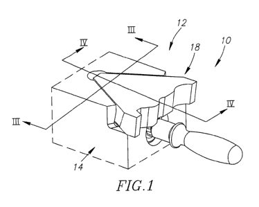
[0025] Attention is drawn to Figs. 1 and 2, showing a cutting portion 10 of a
cutting tool 12.
The cutting tool 12 includes a holder 14 and at least one cutting portion 10
located thereon.
Each cutting portion 10 includes an insert pocket 16 and a cutting insert 18
securely clamped
thereon, via a clamping member 20. The insert pocket 16 is configured only for
clamping
cutting inserts. According to this non-limiting example, the clamping member
20 can be a
screw.
[0026] The insert pocket 16 can include an insert pocket front surface 22
located at a front
end 27 thereof, an insert support surface 24 and two support walls 26. The
insert support
surface 24 can extend rearwardly, from the insert pocket front surface 22
towards the support
walls 26. The support walls 26 can extend upwards, from the insert support
surface 24 to an
insert pocket top surface 28. The insert pocket front surface 22 extends
generally downwards
from the insert support surface 24. The support walls 26 converge towards an
insert pocket
rear end 29, away from the insert pocket front surface 22. The support walls
26 converge
upwards, in a direction away from the insert support surface 24.
[0027] The insert pocket 16 can include a housing 30 which can open out to the
insert
support surface 24. The housing 30 can also open out to the insert pocket
front surface 22.
- 4 -
CA 02827813 2013-08-20
WO 2012/114326 PCT/IL2012/000025
The housing 30 can include a housing wall 32 which extends downwards from the
insert
support surface 24. The housing 30 can include a housing peripheral surface
34, which
extends between the housing wall 32 and the insert pocket front surface 22,
generally parallel
to the insert support surface 24. The housing peripheral surface 34 can
include two head
support surfaces 36 which extend along its length. The head support surfaces
36 can have a
rail-like shape, and can be formed to provide support against bending of the
clamping
member 20,
[0028] Attention is drawn to Figs. 3 to 5. The housing 30 can include a
threaded bore 38
which can open out to the housing wall 32. The bore 38 has a longitudinal bore
axis B which
can extend generally parallel to the insert support surface 24. The clamping
member 20 can
be threadingly received in the bore 38. According to this, non-limiting
example, the clamping
member 20 can have a threaded portion 40 which extends from a head 42. The
head 42
includes a head clamping surface 44 which faces the threaded portion 40, and
an opposing
head abutment surface 46. The clamping member 20 can include a recess which
opens out to
the head abutment surface 46, and configured for transferring torque, i.e.,
communicating
with a key for tightening the clamping member 20. The head 42 can include a
head
peripheral surface 48 which extends between the head clamping surface 44 and
the head
abutment surface 46. The bore 38 is positioned adjacent the insert support
surface 24, such
that when the clamping member 20 is threaded into the bore 38, an exposed head
portion 50
of the head 42, and consequently, an exposed clamping surface 52 of the head
clamping
surface 44, are raised above, or protrude from, the insert support surface 24.
The exposed
head portion 50 and the exposed clamping surface 52 are defined with respect
to a given
angular orientation of the clamping member 20, and not as a specific portion
of the head 42,
or the head clamping surface 44. The holder 14 can include a washer 54, for
reducing wear.
The washer is located between the head 42 and the housing wall 32. The washer
54 includes
two opposing washer abutment surfaces 56, and may have a washer thread 58, for
preventing
the washer 54 from moving freely along the clamping member 20, when it is
turned.
[0029] The cutting insert 18 is typically made of extremely hard and wear-
resistant material
such as cemented carbide, either by form-pressing or by injection molding and
sintering
carbide powders in a binder. The cemented carbide may be, for example,
tungsten carbide.
The cutting insert 18 may be coated or uncoated.
[0030] The cutting insert 18 can have a basic triangular shape and has no
through holes.
The cutting insert 18 includes opposing first and second major surfaces 60, 62
which define a
-5-
CA 02827813 2013-08-20
WO 2012/114326 PCT/IL2012/000025
thickness dimension of the cutting insert. The cutting insert 18 includes a
mid plane P which
is located midway between the major surfaces 60, 62. The mid plane P can be
parallel to
either one or both major surfaces 60, 62. The cutting insert 18 includes two
side surfaces 64
which extend between the major surfaces 60, 62. Each side surface 64 can
include one side
abutment surface 66. The cutting insert 18 has an insert front end 67 and an
insert rear end 69
which define a front-to-rear direction of the cutting insert. The cutting
insert 18, at the insert
front end 67, includes an insert front surface 68 which extends between the
major surfaces 60,
62 and between the side surfaces 64. The side abutment surfaces 66 converge in
a direction
away from the second major surface 62. The side surfaces 64 converge in a
direction away
from the insert front surface 68 towards the insert rear end 69. The cutting
insert 18 can
include an insert rear surface 70 which extends between the side surfaces 64
and between the
major surfaces 60, 62. When the cutting insert 18 is seated in the insert
pocket 16, the insert
rear surface 70 does not contact any portion of the insert pocket 16.
[00311 The second major surface 62 can include a front abutment surface 72
located
adjacent the insert front surface 68, and a rear abutment surface 74 located
adjacent the insert
rear end 69 (as shown in Fig. 5). A portion of the first major surface 60
adjacent the insert
front surface 68 is configured with rake surface 76. At least a portion of he
insert front
surface 68 adjacent the first major surface 60 can be configured with a relief
surface 78. The
first major surface 60 can merge with the front surface 68 and with the side
surfaces 64 at an
edge, at least a portion of which can include a cutting edge 80. At least a
portion of the edge
between the first major surface 60 and the front surface 68 can be configured
as a cutting edge
80. The rake surface 76 and the relief surface 78 meet at the cutting edge 80.
[0032] The cutting insert 18 includes a clamping recess 82 (shown in Figs. 3,
4 and 5)
which opens out to the second major surface 62 and/or to the insert front
surface 68. The
clamping recess 82 can open out to the second major surface 62 at a non-round
opening 83.
The clamping recess 82 is located entirely between the second major surface 62
and the mid
plane P. In other words, the clamping recess 82 does not extend beyond the mid
plane P in
the thickness direction of the cutting insert 18. The clamping recess 82
cannot constitute, or
function as, a rake surface. It other words, the clamping recess cannot
function as a chip
conveying surface. In a front view of the cutting insert 18, a cross-section
of the clamping
recess 82 can have a preferably minimal arched shape (shown in Fig. 3), in
order to
accommodate the exposed head portion 50 of the head 42. The arched shape is
chosen so that
- 6 -
CA 02827813 2013-08-20
WO 2012/114326 PCT/IL2012/000025
the clamping recess 82 can be as small as possible. The clamping recess 82 can
have any
other shape, suitable for receiving the clamping member 20.
[0033] The clamping recess 82 can include a substantially planar insert
abutment surface
84, and an opposite, substantially planar insert clamping surface 86. The
insert clamping
[0034] The opening 83 can have a substantially rectangular shape, in order to
match the
[0035] The insert clamping surface 86 is configured to match the shape of, and
engage, the
[0036] A length L of the insert clamping surface 86 is measured between the
second major
surface 62 and the deepest point of the insert clamping surface 86 in the
clamping recess 82,
[0037] In order to clamp the cutting insert 18 in the insert pocket 16, a
person operating the
cutting tool 12, or operator, can follow these steps: a. Slightly tightening
the clamping
-7-
CA 02827813 2013-08-20
WO 2012/114326 PCT/IL2012/000025
member 20 in the bore 38. b. Place the cutting insert 18 in the insert pocket
16, on top of the
insert support surface 24, while the second major surface 62 faces the insert
support surface
24 and the side surfaces 64 are each generally aligned with, or parallel to,
each respective
support wall 26. In the current position, the insert rear surface 70 faces the
insert pocket rear
end 29. c. Tighten the clamping member 20, until the exposed head portion 50
is
accommodated by, the clamping recess 82, thus allowing the cutting insert 18
to slightly drop
downwards inside the insert pocket 16. d. Tighten the clamping member 20
further, until the
cutting portion 10 reaches an assembled position. In the assembled position of
the cutting
portion 10, the cutting insert 18 is securely clamped in the insert pocket 16
of the holder 14.
The front and rear abutment surfaces 72, 74 of the second major surface 62
abut the insert
support surface 24. Each side abutment surface 66 abuts a respective support
wall 26. The
clamping member 20 is screw threaded into the bore 38, and the exposed head
portion 50 is
accommodated by the clamping recess 82. According to embodiments where the
holder 14
does not include a washer 54, the head clamping surface 44 abuts the insert
clamping surface
86. According to embodiments where the holder 14 includes a washer 54, one
washer
abutment surface 56 abuts the head clamping surface 44, and the other washer
abutment
surface 56 abuts the insert clamping surface 86 (see Fig. 5). The head
peripheral surface 48
does not necessarily abut the head support surfaces 36.
[0038] After
the cutting insert 18 has become worn, in order to replace the cutting insert
18, the operator only needs to untighten the clamping member 20 a few turns
(without
completely removing the clamping member 20 from the bore 38), and the cutting
insert 18
should be easy to lift from the insert pocket 16. However, the cutting insert
18 may become
stuck, and simply relieving the pressure on the cutting insert 18, may not be
enough in order
to release it from the friction forces generated with the support walls 26. In
order to release
the cutting insert 18, the operator may further turn the clamping member 20
until its head
abutment surface 46 engages the insert abutment surface 84, and pushes the
cutting insert 18
out of the insert pocket 16.
[0039] There are at least two advantages to the generally parallel orientation
of the clamping
member 20 with respect to the major surfaces 60, 62 of the cutting insert 18.
[0040] The first is that, in arrangements in which the clamping member 20 is a
screw, the
amount of clamping force achievable in the elongated direction of the screw,
is greater than
the amount of eccentric clamping force achieved with generic arrangements, in
which the
- 8 -
CA 02827813 2013-08-20
WO 2012/114326 PCT/IL2012/000025
clamping screw is screw threaded in the insert pocket, through the major
surfaces of a cutting
insert, and perpendicularly thereto.
[0041] The second advantage is that the cutting insert does not have a
weakening through
screw bore. Consequently, the cutting insert can be designed with an obstacle-
free first major
surface, about which chips can flow freely.
[0042] The description above includes exemplary embodiments and details for
enablement,
if needed, of claimed subject matter, and does not exclude non-exemplified
embodiments and
details from the claim scope of the present application.
- 9 -