Note: Descriptions are shown in the official language in which they were submitted.
11-0268-PCT CA 02828048 2013-08-22
WO 2013/002874
PCT/US2012/033111
SHAPE MEMORY ALLOY ACTUATOR SYSTEM AND METHOD
FIELD
The present disclosure relates generally to actuator systems and, more
particularly, to a shape memory alloy torsion actuator, lock and retract
mechanism.
BACKGROUND
Aircraft typically include a variety of movable aerodynamic devices for
directional control of the aircraft and for altering the lift characteristics
of the aircraft. For
example, fixed wing aircraft typically includes slats and flaps mounted to the
leading and
trailing edges of the wings. Certain aircraft may include Krueger flaps
mounted to the
inboard section of the wings on the leading edge and slats mounted to the
outboard
section of the wings on the leading edge. Krueger flaps and slats may be
deployed
from the leading edge of the wings during certain phases of flight in order to
increase
effective wing camber and maintain airflow over the wings at high angles of
attack.
Flaps may also be mounted to the trailing edges of the wings in order to
increase the lift generated by the wings when the aircraft is moving at
relatively low
airspeeds. For example, trailing edge flaps may be deployed generally
downwardly
during takeoff to increase lift and may then be retracted during the cruise
portion of the
flight. The trailing edge flaps may again be deployed during the approach and
landing
phases of the flight in order to increase lift by increasing effective wing
camber and wing
area to compensate for the lower airspeed of the aircraft.
In addition, certain aircraft may include Gurney flaps which may be mounted to
the wings to improve lift. Gurney flaps may be configured as small spanwise
protrusions which may be deployable generally perpendicularly from the wing
trailing
edge on the underside of the wings to increase the wing lift coefficient when
the aircraft
is moving at relatively high airspeeds such as during cruise flight. Gurney
flaps may
increase the wing lift coefficient without significantly increasing drag by
extending no
further than the boundary layer of airflow passing over the wings. Gurney
flaps may
-1-
11-0268-PCT CA 02828048 2013-08-22
WO 2013/002874
PCT/US2012/033111
maintain attachment of the airflow over the wing surface and thereby improve
the
aerodynamic efficiency of the wings which may reduce fuel consumption.
Aerodynamic devices such as the above-mentioned flaps and slats are
required by the Federal Aviation Administration (FAA) to include a locking
mechanism
for maintaining the device in the selected deployed position without
intervention by the
pilot. FAA regulations additionally allow for automatic retraction of
aerodynamic devices
from the deployed position in certain circumstances. For example, aerodynamic
devices may be automatically retracted upon the aircraft encountering wind
shear to
avoid overloading the wing structure. For an aircraft fitted with Gurney flaps
and moving
at 500 to 600 miles per hour typical of cruise flight, it may be necessary to
retract or
release the Gurney flaps in a relatively short period of time (e.g., less than
300
milliseconds) to prevent overloading the wing.
The prior art includes several actuators such as hydraulic and electro-
mechanical actuators for deploying and retracting aerodynamic devices.
Although
generally effective for their intended purpose, hydraulic and electro-
mechanical
actuators may have a relatively low specific holding torque for maintaining an
aerodynamic device in a deployed position and therefore must be relatively
large in
physical size to generate sufficient holding torque to lock the aerodynamic
device in the
deployed position. Unfortunately, the relatively large physical size of prior
art actuators
presents challenges in integrating the actuator into the narrow confines of
the wing
trailing edge. In addition, the relatively large physical size of such
actuators increases
weight, complexity and cost of the aircraft. Furthermore, such prior art
actuators may
lack the ability to retract or release an aerodynamic device such as a Gurney
flap from
its deployed position in an extremely short period of time upon encountering
wind shear
for an aircraft moving at relatively high airspeeds.
As can be seen, there exists a need in the art for an actuator which is of
relatively small size and which can generate a relatively large amount of
holding torque
for maintaining a deployable device in a deployed position. Furthermore, there
exists a
need in the art for an actuator capable of retracting or releasing a deployed
device in a
relatively short period of time on the order of milliseconds.
-2-
CA 02828048 2015-04-08
SUMMARY
In one embodiment, disclosed is an actuator system, comprising: a housing; a
clutch having clutch plates and a clutch shaft, the clutch plates being
axially engageable
with one another causing the clutch shaft to be coupled to an output shaft; a
shape
memory alloy (SMA) torque tube for rotating the clutch shaft; a first
unidirectional bearing
limiting rotation of the clutch shaft relative to the SMA torque tube to a
first direction; a
second unidirectional bearing preventing rotation of the clutch shaft relative
to the
housing along a second direction opposite the first direction; and an over-
center linkage
coupled to the clutch and configured to axially disengage the clutch plates.
In another embodiment, disclosed is an actuator system, comprising: a clutch
having clutch plates and a clutch shaft; an over-center linkage; a shape
memory alloy
(SMA) linear actuator coupled to the over-center linkage and linearly
contracting when
heated causing locking of the over-center linkage and causing the clutch
plates to axially
engage with one another and causing the clutch shaft to be coupled to an
output shaft;
and an SMA ribbon coupled to the over-center linkage and linearly contracting
when
heated causing collapse of the over-center linkage and axial disengagement of
the clutch
plates from one another.
In another embodiment, disclosed is a method of rotating a shaft relative to a
housing, comprising the steps of: coupling a clutch to an over-center linkage;
axially
engaging clutch plates of the clutch having a clutch shaft; coupling the
clutch shaft to an
output shaft in response to axially engaging the clutch plates; heating an SMA
torque
tube; twisting the SMA torque tube in response to heating thereof; rotating
the output
shaft in response to twisting the SMA torque tube; limiting rotation of the
clutch shaft
relative to the SMA torque tube to a first direction using a first
unidirectional bearing;
preventing rotation of the clutch shaft relative to the housing along a second
direction
opposite the first direction using a second unidirectional bearing; and
disengaging the
clutch plates using the over-center linkage.
In another embodiment, disclosed is a method of disengaging a clutch,
comprising
the steps of: coupling the clutch to an over-center linkage, the clutch having
clutch plates
being axially engaged to one another, the clutch plates being coupled to an
output shaft;
-3-
CA 02828048 2015-04-08
heating an SMA ribbon coupled to the over-center linkage; linearly contracting
the SMA
ribbon in response to the heating thereof; collapsing the over-center linkage
in response
to linearly contracting the SMA ribbon; and disengaging the clutch plates in
response to
collapsing the over-center linkage.
In another embodiment, disclosed is an actuator assembly having a housing, a
shaft, a shape memory alloy (SMA) torque tube, and first and second
unidirectional
bearings. The SMA torque tube may rotate the shaft. The first unidirectional
bearing may
limit rotation of the shaft relative to the SMA torque tube to a first
direction. The second
unidirectional bearing may prevent rotation of the shaft relative to the
housing along a
second direction opposite the first direction.
In a further embodiment, disclosed is an over-center linkage, an SMA linear
actuator, and an SMA ribbon. The SMA linear actuator may be coupled to the
over-center
linkage and may linearly contract when heated causing locking of the over-
center linkage
and engagement of the clutch. The SMA ribbon may linearly contract when heated
causing collapse of the over-center linkage and disengagement of the clutch.
Also disclosed is a method of rotating a shaft relative to a housing. The
method
may include heating an SMA torque tube and twisting the SMA torque tube in
response to
heating thereof. The method may further include rotating the shaft in response
to twisting
the SMA torque tube. Additionally, the method may include limiting rotation of
the shaft
relative to the SMA torque tube to a first direction using a first
unidirectional bearing, and
preventing rotation of the shaft relative to the housing along a second
direction opposite
the first direction using a second unidirectional bearing.
In a further embodiment, disclosed is a method of disengaging a clutch
including
the steps of coupling the clutch to an over-center linkage, and heating an SMA
ribbon
coupled to the over-center linkage. The method may further include linearly
contracting
the SMA ribbon in response to the heating thereof. In addition, the method may
include
collapsing the over-center linkage in response to linearly contracting the SMA
ribbon, and
disengaging the clutch in response to collapsing the over-center linkage.
In a further embodiment, there is disclosed an actuator system, comprising: a
clutch; an over-center linkage; a shape memory alloy (SMA) linear actuator
coupled to
-3a-
CA 02828048 2015-04-08
the over-center linkage and linearly contracting when heated causing locking
of the over-
center linkage and engagement of the clutch; and an SMA ribbon coupled to the
over-
center linkage and linearly contracting when heated causing collapse of the
over-
-3b-
11-0268-PCT CA 02828048 2013-08-22
WO 2013/002874
PCT/US2012/033111
center linkage and disengagement of the clutch. Further comprising: a
bellcrank
configured to collapse the over-center linkage in response to heating of the
SMA ribbon;
further comprising: an SMA torque tube; the clutch including a clutch shaft;
and the
SMA torque tube being coupled to the clutch shaft for rotating the clutch
shaft; a
housing; a first unidirectional bearing limiting rotation of the clutch shaft
relative to the
SMA torque tube to a first direction; a second unidirectional bearing
preventing rotation
of the clutch shaft relative to the housing along a second direction opposite
the first
direction; an output shaft; the clutch coupling the clutch shaft to the output
shaft during
engagement of the clutch by the SMA linear actuator.
In a further embodiment, there is disclosed a method of disengaging a clutch,
comprising the steps of: coupling the clutch to an over-center linkage;
heating an SMA
ribbon coupled to the over-center linkage; linearly contracting the SMA ribbon
in
response to the heating thereof; collapsing the over-center linkage in
response to
linearly contracting the SMA ribbon; and disengaging the clutch in response to
collapsing the over-center linkage. And further comprising the steps of:
coupling the
over-center linkage to an SMA linear actuator; heating the SMA linear
actuator; linearly
contracting the SMA linear actuator in response to heating thereof; and
engaging the
clutch in response to linearly contracting the SMA linear actuator. Wherein
the clutch
includes a clutch shaft, the method further comprising the steps of: coupling
an SMA
torque tube to the clutch shaft; heating the SMA torque tube; and rotating the
clutch
shaft in response to heating the SMA torque tube; wherein the step of coupling
the SMA
torque tube to the clutch shaft comprises: coupling the SMA torque tube to the
clutch
shaft using a first unidirectional bearing; coupling the clutch shaft to a
housing using a
second unidirectional bearing; limiting rotation of the clutch shaft relative
to the SMA
torque tube to a first direction; and preventing rotation of the clutch shaft
relative to the
housing along a second direction opposite the first direction. Wherein the
shaft
comprises a clutch shaft of a clutch, the method further comprising the steps
of:
engaging the clutch; coupling the clutch shaft to an output shaft in response
to
engagement of the clutch; coupling a deployable device to the output shaft;
and rotating
the deployable device in response heating the SMA torque tube.
The features, functions and advantages that have been discussed can be
achieved independently in various embodiments of the present disclosure or may
be
-4-
11-0268-PCT CA 02828048 2013-08-22
WO 2013/002874
PCT/US2012/033111
combined in yet other embodiments, further details of which can be seen with
reference
to the following description and drawings below.
BRIEF DESCRIPTION OF THE DRAWINGS
These and other features of the present disclosure will become more apparent
upon reference to the drawings wherein like numerals refer to like parts
throughout and
wherein:
FIG. 1 is a top view illustration of an aircraft having one or more deployable
devices which may be mounted to the aircraft such as to the leading and
trailing edges
of the aircraft wings;
FIG. 2 is a top view of a portion of the trailing edge of the aircraft wing
taken
along line 2 of FIG. 1 and illustrating an actuator system operatively coupled
to a split
flap mounted to the trailing edge of the wing;
FIG. 3 is a sectional view of the trailing edge of the wing taken along line 3
of
FIG. 2 and illustrating the deployed position of the split flap;
FIG. 4 is a side view of the actuator system illustrating a housing of the
actuator system and an output shaft extending from the housing;
FIG. 5 is an end view of the actuator system taken along line 5 of FIG. 4 and
illustrating the output shaft and a shape memory alloy (SMA) linear actuator
coupled to
the housing;
FIG. 6 is a sectional illustration of the actuator system taken along line 6
of
FIG. 5 and illustrating an SMA torque tube, a clutch, an over-center linkage,
and the
SMA linear actuator for engaging the clutch such that rotational motion of the
SMA
torque tube is transmitted through the clutch to the output shaft;
FIG. 7 is a forward perspective illustration of the actuator system with the
housing omitted for clarity in illustrating the components that make up the
actuator
system;
FIG. 8 is an aft perspective illustration of the actuator system with the
housing
omitted;
FIG. 9 is a sectional illustration of the actuator system taken along line 9
of
FIG. 6 and illustrating a first unidirectional bearing coupling a clutch shaft
to the SMA
torque tube;
-5-
11-0268-PCT CA 02828048 2013-08-22
WO 2013/002874
PCT/US2012/033111
FIG. 9A is a sectional illustration of a portion of the first unidirectional
bearing
taken along line 9A of FIG. 9 and illustrating inner and outer races rotating
in the same
direction;
FIG. 9B is a sectional illustration of the portion of the first unidirectional
bearing
taken along line 9B of FIG. 9 and illustrating the inner and outer races
rotating in
opposite directions relative to one another;
FIG. 10 is a sectional illustration of the actuator system taken along line 10
of
FIG. 6 and illustrating a second unidirectional bearing coupling the clutch
shaft to the
housing;
FIG. 11 is a sectional illustration of the actuator system taken along line 11
of
FIG. 6 and illustrating inner and outer clutch plates respectively coupled to
the output
shaft and a clutch cup;
FIG. 12 is a sectional illustration of the actuator system taken along line 12
of
FIG. 6 and illustrating a yoke pivotably mounted to the housing;
FIG. 13 is a perspective illustration of an SMA ribbon coupled to an over-
center linkage for disengaging the clutch;
FIG. 14 is side sectional illustration of the actuator system taken along line
14
of FIG. 5 and illustrating a bellcrank for coupling the SMA ribbon to the over-
center
linkage;
FIG. 15 is a top sectional illustration of the actuator system taken along
line 15
of FIG. 14 and illustrating the SMA ribbon extending between the yoke;
FIG. 16 is an end sectional illustration of the actuator system taken along
line
16 of FIG. 15 and illustrating the bellcrank pivotably mounted to the housing;
FIG. 17 is a side view of the actuator system with the clutch disengaged and
the over-center linkage in a centered position;
FIG. 18 is a side view of the actuator system with the SMA linear actuator
linearly contracted during heating causing the over-center linkage to move
into a locked
position and resulting in engagement of the clutch;
FIG. 19 is a side view of the actuator system with the SMA ribbon linearly
contracted during heating causing the over-center linkage to move into a
collapsed
position and resulting in disengagement of the clutch;
-6-
11-0268-PCT CA 02828048 2013-08-22
WO 2013/002874
PCT/US2012/033111
FIG. 20 is a schematic illustration of the actuator system wherein the SMA
linear actuator and the SMA ribbons are in their martensite lengths (i.e., un-
contracted
lengths and the clutch is disengaged;
FIG. 21 is a schematic illustration of the actuator system wherein the SMA
linear actuator is heated causing linear contraction from a first length
corresponding to
the martensite condition to a second length corresponding to an austenite
condition and
resulting in movement of the over-center linkage into a locked position and
engagement
of the clutch;
FIG. 22 is a schematic illustration of the actuator system wherein the SMA
torque tube is heated causing twisting thereof and rotation of the clutch
shaft and
deployable device from a first rotational position to a second rotational
position;
FIG. 23 is a schematic illustration of the actuator system wherein heat is
dissipated from the SMA torque tube causing untwisting thereof and further
illustrating
the clutch shaft and the deployable device being maintained in the second
rotational
position due to the cooperation of the first and second unidirectional
bearings;
FIG. 24 is a schematic illustration of the actuator system wherein the SMA
ribbon is heated causing linear contraction from a first length corresponding
to the
martensite condition to a second length corresponding to the austenite
condition and
resulting in collapsing of the over-center linkage and disengagement of the
clutch
allowing free rotation of the deployable device;
FIG. 25 is an illustration of a flow diagram representing one or more
operations
that may be included in a methodology of engaging a clutch using an SMA linear
actuator;
FIG. 26 is an illustration of a flow diagram representing one or more
operations
that may be included in a methodology of rotating and locking a clutch shaft
of an
actuator system; and
FIG. 27 is an illustration of a flow diagram representing one or more
operations
that may be included in a methodology of controlling a clutch of an actuator
system.
DETAILED DESCRIPTION
Referring now to the drawings wherein the showings are for purposes of
illustrating various embodiments of the disclosure, shown in FIG. 1 is a top
view of an
-7-
11-0268-PCT CA 02828048 2013-08-22
WO 2013/002874
PCT/US2012/033111
aircraft 200 which may incorporate an actuator system 10 (FIG. 2) as disclosed
herein.
The actuator system 10 (FIG. 2) may be adapted for deploying any number of
deployable devices 210 including, but not limited to, aerodynamic devices 212
which
may be mounted to the aircraft 200 illustrated in FIG. 1. The aircraft 200 may
include a
fuselage 202 having an empennage 218 which may include a horizontal stabilizer
224,
an elevator 226, a vertical stabilizer 220 and a rudder 222 for directional
control.
The aircraft 200 in FIG. 1 may include a variety of aerodynamic devices 212
mounted to the leading and trailing edges 206, 208 of the wings 204 for
altering the lift
and drag characteristics of the wings 204. For example, the aerodynamic
devices 212
may comprise leading edge 206 slats and/or flaps such as Krueger flaps which
may be
deployable from the leading edge 206 of the wings 204 to increase the
effective camber
of the wings 204 and maintain airflow over the upper surfaces of the wings 204
at high
angles of attack. The wings 204 may also include spoilers 216 for reducing the
lift of
the wings 204 such as during landing such that the weight of the aircraft 200
may be
transferred to the landing gear for improved braking. The trailing edge 208 of
the wing
204 may incorporate any number of aerodynamic devices 212 including flaps
mounted
to the trailing edges 208 of the wings 204. The flaps may be of any
configuration
without limitation including splits flaps, slotted flaps and Gurney flaps for
improving the
lift characteristics of the wings 204.
Referring to FIG. 2, shown is a portion of the trailing edge 208 of the wing
204
of FIG. 1 and illustrating an actuator system 10 operatively coupled to a
deployable
device 210 such as the split flap 214. The actuator system 10 in FIG. 2 may be
configured to deploy and retract the split flap 214. For example, the split
flap 214 may
be deflected downwardly during deployment as shown in FIG. 3 such as by
heating a
shape memory alloy (SMA) torque tube 18 (FIG. 6) causing rotation of the
deployable
device 210. As will be described in greater detail below, the actuator system
10 (FIG. 2)
advantageously includes an SMA linear actuator 120 (FIG. 4) for applying a
relatively
high axial force on the clutch 60 to provide a relatively high specific
holding torque for
maintaining a deployed position of the deployable device 210 under load. In
addition,
the actuator system 10 (FIG. 2) advantageously includes unidirectional
bearings 32, 36
(FIG. 6) for passively locking the deployable device 210 in the desired
position after
deployment by the SMA torque tube 18. Furthermore, the actuator system 10
-8-
CA 02828048 2015-04-08
advantageously includes one or more SMA wires or ribbons 150 (FIG. 7) for
rapidly
releasing the deployable device 210 when desired. For example, the actuator
system 10
may maintain the split flap 214 (FIG. 3) at a desired flap setting and may
rapidly release
the split flap 214 in a relatively short period of time (e.g., less than 300
milliseconds)
when the aircraft 200 encounters turbulence or other loading conditions.
Referring to FIG. 4, shown is a side view of the actuator system 10 housed
within
a housing 12. The actuator system 10 may include a shape memory alloy (SMA)
torque
tube 18 for deploying and retracting the deployable device 210 (FIG. 2). The
SMA torque
tube 18 may include a fixed end 26 having splines 28 or other features for
fixedly
coupling the fixed end 26 to the housing 12. The deployable device 210 (FIG.
2) may be
mounted to an output shaft 90 of the actuator system 10. The SMA torque tube
18 may
be trained to twist when heated causing deployment of the deployable device
210 (FIG.
2) as described below. The deployable device 210 may include a position sensor
(not
shown) to monitor the position of the deployable device 210 for feedback
control of the
SMA torque tube 18.
Referring to FIG. 5, shown is an end view of the housing 12 illustrating the
output
shaft 90 which may be retained within the housing 12 by a retainer mechanism
96 such
as an internal snap ring or by other suitable means. Also shown is a fixed end
124 of the
SMA linear actuator 120 which may be fixedly coupled to the housing 12 and
retained to
the housing 12 by a retainer mechanism 96 such as an external snap ring or
other
means. The housing 12 may be comprised of a first housing portion 14 and a
second
housing portion 16 which may be divided along a vertical parting plane to
facilitate
assembly and maintenance of the actuator system 10. However, the housing 12
may be
provided in alternative configurations including, but not limited to, a
unitary housing
configuration or housing configurations includes more than two housing
portions. Further
in this regard, it is contemplated that the housing 12 may comprise one or
more mounting
brackets (not shown) or fittings (not shown) for mounting the components of
the actuator
system 10 to a structure such as an internal structure (not shown) of a wing.
In this
regard, the housing 12 is not necessarily limited to a housing configuration
wherein the
actuator system 10 components are contained within an interior of the housing
12.
-9-
11-0268-PCT CA 02828048 2013-08-22
WO 2013/002874
PCT/US2012/033111
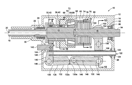
Referring to FIGS. 6-8, shown are the components of the actuator system 10.
FIG. 6 illustrates the components housed within the housing 12. As shown in
FIG. 6,
the SMA torque tube 18 extends from the fixed end 26 (FIG. 4) through an
elongated
portion of the housing 12. A drive end 30 of the SMA torque tube 18 may be
rotatably
supported by a torque tube bearing 24 (FIG. 6) such as a needle bearing that
may be
mounted to the housing 12. As shown in FIG. 6, the SMA torque tube 18 may
include a
hollow interior for housing 12 a heater 122 for heating the SMA torque tube
18.
The SMA torque tube 18 may be formed of a suitable SMA material. For
example, the SMA material may comprise nickel-titanium such as nitinol. The
SMA
material may have a two-way shape effect to allow the SMA torque tube 18 to
twist from
an original shape to a trained shape and twist back from the trained shape to
the
original shape. The SMA torque tube 18 may be trained to twist by repeatedly
torquing
the SMA torque tube 18 to a predetermined stress level (e.g., 15-20 ksi). When
the
SMA torque tube 18 is heated above a transition temperature, the SMA material
reaches an austenite condition causing the SMA torque tube 18 to untwist and
resume
its original pre-twisted shape. When heat is allowed to dissipate such that
the SMA
torque tube 18 cools below the transition temperature, the SMA torque tube 18
returns
to its original shape in the martensite condition. In this manner, the SMA
torque tube 18
provides a means for deploying the deployable device 210 (FIG. 2) by heating
the SMA
torque tube 18. The clutch 60 and the first and second unidirectional bearings
32, 36
maintain the deployable device 210 in the deployed position while the SMA
torque tube
18 is allowed to cool and return to its original untwisted shape.
FIG. 6 illustrates an SMA end fitting 22 of the SMA torque tube 18 coupled to
the clutch shaft 62 by a first unidirectional bearing 32. The clutch shaft 62
may be
rotatably supported or coupled to the housing 12 by means of a second
unidirectional
bearing 36. The first unidirectional bearing 32 limits rotation of the clutch
shaft 62
relative to the SMA torque tube 18 to a first direction 34. The second
unidirectional
bearing 36 prevents rotation of the clutch shaft 62 relative to the housing 12
along a
second direction 38 opposite the first direction 34. The first and second
unidirectional
bearings 32, 36 provide a means to passively lock the clutch shaft 62 and the
deployable device 210 in a desired rotational position after deployment by the
SMA
torque tube 18. Such an arrangement may obviate the need to continuously
supply
-10-
11-0268-PCT CA 02828048 2013-08-22
WO 2013/002874
PCT/US2012/033111
electrical power to heat to the SMA torque tube 18 to maintain the deployable
device
210 (FIG. 3) in the deployed position. In this manner, the actuator assembly
10 may
advantageously reduce consumption of electrical power from the aircraft power
system.
FIG. 9 illustrates the first unidirectional bearing 32 coupling the clutch
shaft 62
to the SMA torque tube 18 (FIG. 6).
In a non-limiting embodiment, the first
unidirectional bearing 32 may be configured as a sprag bearing 42 having
coaxial inner
and outer races 44, 48 and a plurality of sprags 52 that limit rotation of the
inner and
outer races 44, 48 to a single direction relative to one another. The outer
race 48 may
be mounted non-rotatably coupled to the SMA end fitting 22 by means of a key
40 or
other means. The inner race 44 may be non-rotatably coupled to the clutch
shaft 62 by
means of a key 40 or other means to fixedly couple the inner race 44 to the
clutch shaft
62.
FIG. 9A is an enlarged view of a portion of the sprag bearing 42 of FIG. 9 and
illustrating a plurality of sprags 52 limiting rotation of the inner race 44
relative to the
outer race 48 to a single direction. Each one of the sprags 52 may be
rotatable about a
sprag pivot 54 along a direction of rotation 56 that allows rotation of the
inner race 44
relative to the outer race 48. Conversely, FIG. 9B illustrates the rotation of
the sprags
52 in an opposite direction 58 as may occur during attempts to rotate the
inner race 44
along a direction of rotation 46 that is opposite to the direction of rotation
50 of the outer
race 48. The sprags 52 may optionally be spring-loaded to maintain
substantially
continuous contact with the inner and outer races 46, 48 to minimize backlash.
FIG. 10 illustrates the second unidirectional bearing 36 coupling the clutch
shaft 62 to the housing 12. The outer race 48 of the second unidirectional
bearing 36
may be coupled to the housing 12 by means of a key 40. Likewise, the inner
race 44 of
the second unidirectional bearing 36 may be coupled to the clutch shaft 62 by
means of
a key 40. The second unidirectional bearing 36 may be arranged in the same
orientation as the first unidirectional bearing 32 (FIG. 9) to prevent
rotation of the clutch
shaft 62 relative to the housing 12 along a second direction 38 opposite the
first
direction 34. For example, the sprags 52 of the first unidirectional bearing
32 may be
oriented in the same direction as the sprags 52 of the second unidirectional
bearing 36.
Collectively, the first and second unidirectional bearings 32, 36 form a
passive lock for
limiting rotation of the clutch shaft 62 to a single direction while allowing
the SMA torque
-11-
11-0268-PCT CA 02828048 2013-08-22
WO 2013/002874
PCT/US2012/033111
tube 18 (FIG. 6) to return to its original shape after the SMA torque tube 18
rotates the
clutch shaft 62 to the desired rotational position.
Although the first and second unidirectional bearings 32, 36 are described as
sprag bearings 42, other unidirectional bearing configurations are
contemplated for
coupling the clutch shaft 62 to the SMA torque tube 18 and for coupling the
clutch shaft
62 to the housing 12. For example, the unidirectional bearings may be
configured as
unidirectional ball bearings (not shown). Even further, the unidirectional
bearings may
be configured as a ratchet-and-pawl arrangement (not shown).
Referring to FIG. 6, the clutch shaft 62 and clutch 60 may be supported by a
thrust bearing 64 that may be mounted to the housing 12. The thrust bearing 64
may
radially (i.e., rotatably) support the clutch shaft 62. In addition, the
thrust bearing 64
may be in axial contact with the clutch cup 74 of the clutch 60 to provide
axial resistance
against axial loads placed on the clutch 60 during engagement. Such axial
loads may
be applied by the SMA linear actuator via a yoke 100. The yoke may include one
or
more protrusions 102 as best seen in FIG. 7. A protrusion 102 of the yoke 100
may
apply axial pressure to a thrust bearing 64. The thrust bearing 64 may
distribute the
pressure from the yoke 100 to the clutch plates 76, 78 causing relative axial
motion and
engagement of the inner and outer clutch plates 76, 78.
In FIG. 6, in a non-limiting embodiment, the thrust bearing 64 may be
configured as a tapered roller bearing. The tapered roller bearing 66 may be
comprised
of inner and outer races 68, 70 which may have conical surfaces and a
plurality of
rollers 72 captured between the inner and outer races 68, 70. The rollers 72
may be
angularly (i.e., conically) oriented as shown in FIG. 6 to provide radial
support for the
clutch shaft 62 and axial support for the clutch 60. Although the thrust
bearing 64 is
shown as a tapered roller bearing 66, any bearing configuration capable of
providing
radial and axial support for the clutch shaft 62 and clutch 60 may be
incorporated into
the actuator system 10.
FIG. 6 further illustrates the clutch 60 including the clutch cup 74 and
having a
plurality of inner and outer clutch plates 76, 78. The inner clutch plates 76
may be non-
rotatably engaged to an output shaft 90. The outer clutch plates 78 may be non-
rotatably engaged to the clutch cup 74. For example, FIG. 11 illustrates a
plurality of
tangs 80 formed on the inner clutch plates 76. Each one of the tangs 80 may be
non-
-12-
11-0268-PCT CA 02828048 2013-08-22
WO 2013/002874
PCT/US2012/033111
rotatably engaged to axially-extending shaft grooves 84 formed along the
output shaft
90. FIG. 11 further illustrates a plurality of lobes 82 formed on the outer
clutch plates
78. The lobes 82 may be non-rotatably engaged to axially-extending cup grooves
86
formed within the interior surface of the clutch cup 74.
The inner clutch plates 76 may be substantially equal in quantity to the outer
clutch plates 78. However, the inner and outer clutch plates 76, 78 may be
provided in
unequal quantities. Furthermore, although FIG. 6 illustrates a total of
fourteen inner and
outer clutch plates 76, 78, any quantity may be provided to provide the
desired amount
of holding torque for the clutch 60. The quantity of inner and outer clutch
plates 76, 78,
may be selected based upon the amount of surface area required to provide the
necessary holding torque for reacting aerodynamic loads that may be imposed on
the
deployable device 210 (FIG. 3).
FIG. 6 further illustrates the output shaft 90 rotatably supported by bearings
92
located at opposed ends of the output shaft 90. For example, a left-hand side
of the
output shaft 90 may be rotatably supported by a bearing 92 mounted within the
clutch
shaft 62. A right-hand side of the output shaft 90 may be rotatably supported
by a
bearing 92 mounted to the housing 12. The bearing 92 may be retained to the
housing
12 by a retainer mechanism 96 or other suitable means.
The yoke 100 may be pivotably mounted to the housing 12 and may include a
bore 104 to allow the output shaft 90 to extend through the yoke. However, the
yoke
100 may be provided in alternative configurations such as a fork-shaped
configuration
(not shown) for accommodating the output shaft 90. The yoke 100 may
additionally
include a bore 106 through which the SMA linear actuator 120 may pass. As
shown in
FIG. 12, the yoke 100 may be mounted to the housing 12 on a pivot pin 108
which may
be retained to the housing 12 by means of a retainer mechanism 96. A pair of
spacers
110 on opposite sides of the yoke 100 may maintain the lateral position of the
yoke 100.
The yoke 100 may transmit pressure to the inner and outer clutch plates 76,
78 by means of the protrusion 102 which bears against the bearing plate 88.
The
bearing plate 88 may be mounted to the output shaft 90 and may bear against
the inner
and outer clutch plates 76, 78. The bearing plate 88 may be configured to
accommodate rotation of the clutch plates 76, 78 while the yoke 100 is
applying
pressure to the bearing plate 88.
-13-
11-0268-PCT CA 02828048 2013-08-22
WO 2013/002874
PCT/US2012/033111
Referring to FIGS. 6-8, shown is the interconnection of the yoke 100 to the
over-center linkage 128. The over-center linkage 128 may be comprised of a
first link
130 pivotally connected to a second link 132. The first link 130 may include a
bearing
stop 130a formed on an end of the first link 130 for interfacing with a
bearing stop 132a
formed on an end of the second link 132. For example, FIG. 6 illustrates the
first and
second links 130, 132 abutting one another at the bearing stops 130a, 132a.
The
bearing stops 130a, 132a may limit the amount of lateral movement of the first
and
second links 130, 132 from a centerline 148 extending between the connecting
pins 146
(i.e., pivot points) connecting the first and second links 130, 132 to the
yoke 100 and
end fitting 140, respectively.
The first link 130 may be pivotally connected to the yoke 100 by a connecting
pin 146 as indicated above. The second link 132 may also be pivotally
connected to the
end fitting 140 by a connecting pin 146. The connection between the second
link 132
and the end fitting 140 may be arranged to prevent bending loads on the SMA
linear
actuator 120. In this regard, a guide 142 may be included with the end fitting
140. The
guide 142 may be pivotally mounted to the end fitting 140 and may be axially
slidably
mounted within a guide bore 144 formed in the housing 12. The guide 142 may
minimize or prevent lateral loading of the SMA linear actuator 120 while
allowing the
SMA linear actuator 120 to linearly contract and extend in response to heating
and
cooling of the SMA linear actuator 120.
Referring still to FIG. 6, the SMA linear actuator 120 may include a free end
126 that may be fixedly coupled to the end fitting 140. The free end 126 of
the SMA
linear actuator 120 is free in the sense that the free end 126 may move
axially under the
linear contraction or extension of the SMA linear actuator 120 in response to
heating
and cooling thereof. The fixed end 124 of the SMA linear actuator 120 may be
fixedly
coupled to the housing 12. For example, in the non-limiting embodiment
illustrated in
FIG. 6, the SMA linear actuator 120 may be inserted into a bore formed in the
housing
12. The fixed end 124 may include a flange that may be mounted against an
interior
side of the housing 12. A retainer mechanism 96 such as a snap ring may be
mounted
to the fixed end 124 on an exterior side of the housing 12. As may be
appreciated, the
fixed end 124 may be mounted to the housing 12 in any one of a variety of
alternative
arrangements for fixedly coupling the fixed end 124 to the housing 12.
-14-
11-0268-PCT CA 02828048 2013-08-22
WO 2013/002874
PCT/US2012/033111
The SMA linear actuator 120 may be formed as a generally hollow tubular
member such that a heater 122 may be housed within the SMA linear actuator
120. For
example, the heater 122 may comprise a cartridge heater 122 that may be
inserted into
the SMA linear actuator 120 for applying thermal energy or heat to the SMA
linear
actuator 120. The SMA linear actuator 120 may be trained to linearly contract
when
heated. The linear contraction of the SMA linear actuator 120 causes pivoting
of the
yoke 100 resulting in pressure applied to the clutch plates and engagement of
the clutch
60. The engagement of the clutch 60 rotatably couples the clutch shaft 62 to
the output
shaft 90 such that the clutch shaft 62 and output shaft 90 rotate
substantially in unison
as described in greater detail below.
The SMA linear actuator 120 may be constructed from an SMA material, such
as nitinol, or any other suitable SMA material, such as a nickel-titanium
compound or
other suitable compounds. The SMA material may have a two-way shape effect to
allow the SMA linear actuator 120 to linearly contract from an un-contracted
length in a
martensite condition to a contracted length when heated to an austenite
condition and
to linearly un-contract (i.e., extend) when heat dissipates from the SMA
linear actuator
120. In this regard, the SMA linear actuator 120 undergoes shape change when
heated
from a first temperature, corresponding to the martensite un-contracted
length, to a
second temperature, corresponding to the austenite contracted length. The SMA
linear
actuator 120 may be trained to linearly contract by applying tensile stress
(e.g. 15-20
ksi) to the SMA linear actuator 120 when in a martensite condition and heat-
cycling the
SMA linear actuator 120 through the austenite condition. The material from
which the
SMA linear actuator 120 is fabricated may provide up to at least approximately
4% or
greater recoverable strain when the SMA linear actuator 120 is heated from the
first
temperature to the second temperature. In this regard, the sizing and shape of
the SMA
linear actuator 120 may be based upon the amount of recoverable strain
occurring in
the SMA material upon heating from the austenite condition to the martensite
condition.
For example, for a 4.0 inch length of the SMA linear actuator 120, a 3%
recoverable strain upon heating of the SMA linear actuator 120 would result in
approximately .12 inch of linear contraction of the SMA linear actuator 120.
The amount
of linear contraction may be based upon the amount of axial movement required
to
engage the inner clutch plates 76 to the outer clutch plates 78 of the clutch
60. For
-15-
11-0268-PCT CA 02828048 2013-08-22
WO 2013/002874
PCT/US2012/033111
example, each one of the inner and outer clutch plates 76, 78 may have a
certain
amount of waviness or out-of-plane distortion which may result from the
manufacturing
process of fabricating the inner and outer clutch plates 76, 78. The SMA
linear actuator
120 may be sized to have a length accounting for the cumulative effect of the
waviness
of the inner and outer clutch plates 76, 78. If each one of the inner and
outer clutch
plates 76, 78 has a waviness of approximately .003 inch, then a total of
fourteen clutch
plates would require a minimum of approximately .042 inch of axial
displacement to
accommodate waviness in the inner and outer clutch plates 78 such that the
inner and
outer plates 76, 78 may be frictionally engaged to one another. Additional
axial
displacement may be required in order to accommodate hysteresis, thermal
expansion
of the actuator assembly components, and manufacturing and assembly
tolerances.
FIGS. 13-16 illustrate the mounting of a pair of SMA ribbons 150 to the
actuator system 10. As indicated above, the SMA ribbons 150 provide a means to
disengage the clutch 60 in a relatively short period of time (e.g., in 300
milliseconds or
less). The SMA ribbons 150 may be oriented in substantially parallel relation
to one
another and may extend between the yoke 100 and a bellcrank 160 that may be
mounted to the housing 12. Each one of the SMA ribbons 150 may be formed in a
relatively small diameter to facilitate relatively rapid heating of the SMA
ribbons 150.
Rapid heating of the SMA ribbons 150 may facilitate linear contraction of the
SMA
ribbon 150 in a relatively short period of time and relatively rapid
disengagement of the
clutch 60. The SMA ribbons 150 may be trained to linearly contract or shorten
when
heated from a first temperature corresponding to a martensite condition of the
SMA
ribbons 150 to a second temperature corresponding to an austenite condition of
the
SMA ribbons 150.
The SMA ribbons 150 may be heated by applying electrical current to cause
electrical resistance heating of the SMA ribbons 150. Advantageously, SMA
materials
have relatively high electrical resistance resulting in relatively rapid
heating of the SMA
ribbons 150. The SMA ribbons 150 may be formed from nickel-titanium material
such
as nitinol or other suitable SMA materials. The SMA ribbons 150 may be
provided in a
length that provides an amount of linear contraction for moving the over-
center linkage
128 from the locked position 136 toward the collapsed position 138 as
described below.
In an embodiment, the SMA ribbons 150 may be machined from a solid block or
billet of
-16-
11-0268-PCT CA 02828048 2013-08-22
WO 2013/002874
PCT/US2012/033111
SMA material such as by electrical discharge machining (EDM). By machining the
SMA
ribbons 150, the SMA ribbons 150 may be accurately formed in the desired
thickness
profile. In addition, eyelets 152 (FIG. 7) may be integrally machined into the
SMA
ribbons 150. A fitting 158 may also be machined into an end of the SMA ribbons
150
opposite the eyelets 152. The fitting 158 may facilitate pivotable connection
of the SMA
ribbons 150 to the bellcrank 160.
As shown in FIG. 15, the eyelets 152 may be mounted to the yoke 100 by
means of electrically insulated standoffs 154. Electrical leads 156 at the
ends of the
SMA ribbons 150 may be coupled to a power source (not shown) for applying
current to
the SMA ribbons 150 when disengagement of the clutch 60 is desired. The SMA
ribbons 150 may be pivotally connected to the bellcrank 160 by means of the
fitting 158
machined into the SMA ribbons 150. A connecting pin 146 may extend through an
upper end of the bellcrank 160 and through the fitting 158 as shown in FIGS.
14-16 to
couple the SMA ribbons 150 to the bellcrank 160. The bellcrank 160 may be
pivotably
mounted to the housing 12 by means of a spacer 168 and bellcrank pivot pin
164. The
bellcrank pivot pin 164 may extend through a bore formed in the housing 12 and
may be
retained by a retainer mechanism 96. As may be appreciated, the bellcrank 160
may
be pivotably mounted to the housing 12 by any one of a variety of alternative
arrangements and is not limited to the arrangement illustrated in FIG. 16. For
example,
the bellcrank 160 pin may be threadably engaged to a boss (not shown) formed
on an
interior side of the housing 12.
Referring to FIGS. 13-16, the bellcrank 160 may include a bellcrank stub 166
for applying lateral force to the over-center linkage 128. The bellcrank stub
166 may be
integrally formed with the bellcrank 160 or the bellcrank stub 166 may be
formed as a
separate component that may be mounted to the bellcrank 160. The bellcrank 160
may
pivot in response to linear contraction of the SMA ribbons 150 upon heating of
the SMA
ribbons 150. The pivoting of the bellcrank 160 may cause the bellcrank stub
166 to
contact the first and/or second link 130, 132 and apply lateral force thereto.
The
bellcrank stub 166 may be positioned in a manner to apply lateral force to the
end of at
least one of the first and second links 130, 132. The application of lateral
force may
move the over-center linkage 128 (i.e., move the joined ends of the first and
second
links 130, 132) from the locked position 136 on one side of the centerline 148
toward a
-17-
11-0268-PCT CA 02828048 2013-08-22
WO 2013/002874
PCT/US2012/033111
collapsed position 138 on an opposite side of the centerline 148 under the
load of the
heated (i.e., linearly contracted) SMA linear actuator 120. The collapse of
the over-
center linkage 128 may result in disengagement of the clutch 60. Disengagement
of the
clutch 60 may allow the deployable device 210 to rotate freely as described in
greater
detail below.
Referring to the schematic diagrams of FIGS. 20-24 and with additional
reference to the flow diagrams of FIG. 25-27 and the actuator assembly
illustrations of
FIGS. 17-19, the methodologies of operating the actuator assembly 10 will be
described.
In the flow diagram of FIG. 25, shown is a methodology 300 of engaging the
clutch 60 using the SMA linear actuator 120. In Step 302 of the methodology
300, the
clutch 60 may be coupled to the over-center linkage 128. For example, FIGS. 17
and
illustrate the yoke 100 coupled to the over-center linkage 128. The yoke 100
may
include a protrusion 102 which may be placed in contact with the bearing plate
88 to
apply pressure to the clutch plates 76, 78 when the yoke 100 is pivoted about
the yoke
20 pivot pin 108.
Step 304 of the methodology 300 of FIG. 25 may include coupling the SMA
linear actuator 120 to the over-center linkage 128. As shown in FIGS. 17 and
20, the
free end 126 of the SMA linear actuator 120 may be fixedly coupled to the end
fitting
140. FIG. 20 schematically illustrates the SMA linear actuator 120 at a first
temperature
TI-LA corresponding to a martensite condition of the SMA linear actuator 120
and which
additionally corresponds to a first length 'ILA of the SMA linear actuator
120. When the
SMA linear actuator 120 is at the first temperature 7-1_ LA, the over-center
linkage 128
may be in a centered position 134 as shown in FIG. 17 wherein the first and
second
links 130, 132 are generally aligned with one another.
Step 306 of the methodology 300 of FIG. 25 may include heating the SMA
linear actuator 120 to raise the temperature of the SMA linear actuator 120
from the first
temperature Ti_ LA to the second temperature T2- LA. FIG. 21 schematically
illustrates the
SMA linear actuator 120 in cross-hatching to indicate the heating of the SMA
linear
actuator 120 to the second temperature T2- LA-
Step 308 of the methodology 300 of FIG. 25 may include linearly contracting
the SMA linear actuator 120 in response to heating thereof. As shown in FIG.
21, the
-18-
11-0268-PCT CA 02828048 2013-08-22
WO 2013/002874
PCT/US2012/033111
SMA linear actuator 120 is linearly contracted from the first length li_ LA to
a second
length 12- LA. Due to the linear contraction of the SMA linear actuator 120,
the over-
center linkage 128 may be moved from the centered position 134 illustrated in
FIGS. 17
and 20 to the locked position 136 illustrated in FIGS. 18 and 21. Although not
shown,
the over-center linkage 128 may include a biasing mechanism to bias the over-
center
linkage 128 from the centered position 134 (i.e., past the centerline 148)
toward the
locked position 136 shown in FIG. 18.
In Step 310 of the methodology 300 of FIG. 25, the over-center linkage 128
may be locked in the locked position 136 wherein the bearing stops 130a, 132a
(FIG.
14) of the respective first and second links 130, 132 may be abutted against
one
another to limit the extent of lateral movement of the joined ends of the
first and second
links 130, 132. In response to the linear contraction of the SMA linear
actuator 120, the
yoke 100 may be pivoted about the pivot pin 108 as shown in FIGS. 18 and 21.
The
protrusion 102 of the yoke 100 applies pressure to the bearing plate 88
causing
frictional contact between the inner and outer clutch plates 76, 78.
Step 312 of the methodology 300 of FIG. 25 may include engaging the clutch
60 in response to the pivoting the yoke 100 resulting from the linear
contraction of the
SMA linear actuator 120 when heated. FIGS. 18 and 21 illustrate the clutch 60
in the
engaged position. The SMA linear actuator 120 may remain heated to maintain
the
clutch 60 in the engaged position. The clutch shaft 62 may initially be in a
first rotational
position (9/ as illustrated in FIG. 21.
Step 314 of the methodology 300 of FIG. 25 may include coupling the clutch
shaft 62 to the output shaft 90 in response to engagement of the clutch 60 as
shown in
FIG. 18. The output shaft 90 may be coupled to the deployable device 210 (FIG.
2).
The output shaft 90 may include splines 94 (FIG. 4) for coupling to the
deployable
device 210 such that output shaft 90 and deployable device 210 rotate
substantially in
unison when the clutch shaft 62 is rotated.
Referring now to the flow diagram of FIG. 26, shown is a methodology 400 of
rotating the clutch shaft 62 using the SMA torque tube 18. In Step 402 of the
methodology 400, the SMA torque tube 18 may be rotatably coupled to the clutch
shaft
62 using the first unidirectional bearing 32. The outer race 48 of the first
unidirectional
bearing 32 may be fixedly mounted to the drive end 30 of the SMA torque tube
18 using
-19-
11-0268-PCT CA 02828048 2013-08-22
WO 2013/002874
PCT/US2012/033111
the key 40 illustrated in FIG. 9. The inner race 44 of the first
unidirectional bearing 32
may be fixedly mounted to the clutch shaft 62 using the key 40 or other
suitable means.
Step 404 of the methodology 400 of FIG. 26 may include rotatably coupling the
clutch shaft 62 to the housing 12 using the second unidirectional bearing 36.
The outer
race 48 of the second unidirectional bearing 36 may be fixedly mounted to the
housing
12 using the key 40 as shown in FIG. 10. The inner race 44 of the second
unidirectional
bearing 36 may be fixedly mounted to the clutch shaft 62 using the key 40.
Step 406 of the methodology 400 of FIG. 26 may include heating the SMA
torque tube 18. FIG. 22 illustrates the SMA torque tube 18 in cross-hatching
indicating
the application of heat. The SMA torque tube 18 may be heated by a heater 122
(FIG.
6) that may be housed within a hollow interior of the SMA torque tube 18. The
heater
122 may be electrically powered such as by a power system (not shown) of the
aircraft
200 (FIG. 1).
Step 408 of the methodology 400 of FIG. 26 may include twisting the SMA
torque tube 18 in response to heating of the SMA torque tube 18. FIG. 22
illustrates a
first direction of twisting TT/ of the SMA torque tube 18. The twisting of the
SMA torque
tube 18 may occur when the SMA torque tube 18 reaches an austenite condition.
The
twisting of the SMA torque tube 18 in response to heating comprises an
untwisting of
the SMA torque tube 18 from its trained shape toward its original untwisted
shape as
described above.
Step 410 of the methodology 400 of FIG. 26 may include rotating the clutch
shaft 62 in response to twisting the SMA torque tube 18. The first
unidirectional bearing
32 transmits twisting motion at the drive end 30 of the SMA torque tube 18
into
rotational motion of the clutch shaft 62. FIG. 22 illustrates the clutch shaft
62 rotating
along a first direction of rotation Rcs_i from the first rotational position
el to a second
rotational position e2.
Step 412 of the methodology 400 of FIG. 26 may include limiting rotation of
the
clutch shaft 62 relative to the SMA torque tube 18 to a first direction 34
(FIG. 9). For
example, FIG. 9 illustrates the arrangement of the first unidirectional
bearing 32 such
that the rotation of the clutch shaft 62 is limited to a clockwise direction
relative to the
SMA torque tube 18. Rotation of the clutch shaft 62 in a counter-clockwise
direction
relative to the SMA torque tube 18 is prevented.
-20-
11-0268-PCT CA 02828048 2013-08-22
WO 2013/002874
PCT/US2012/033111
Step 414 of the methodology 400 of FIG. 26 may include rotating the
deployable device 210 in response to rotating the clutch shaft 62 when the
clutch 60 is
engaged. FIG. 22 illustrates the rotation of the output shaft 90 in the same
direction as
the rotation of the clutch shaft 62. The output shaft 90 is fixedly coupled to
the
deployable device 210 such that the deployable device 210 rotates along a
first
direction of rotation R0s4 in unison with the rotation of the output shaft 90.
Step 416 of the methodology 400 of FIG. 26 may include preventing rotation of
the clutch shaft 62 relative to the housing 12 along the second direction 38
of rotation
opposite the first direction 34 (FIG. 9). In the exemplary arrangement of the
first
unidirectional bearing 32 as shown in FIG. 9, the clutch shaft 62 is limited
to rotation
along a first, counter-clockwise direction relative to the SMA torque tube 18.
FIG. 23
illustrates the twisting of the SMA torque tube 18 as a result of de-
activation of the
heater 122 causing heat to dissipate from the SMA torque tube 18. The
dissipation of
heat from the SMA torque tube 18 may result in twisting of the SMA torque tube
18
along a direction TT2 (FIG. 23) as the SMA torque tube 18 returns to its
trained or
twisted shape as described above.
The return of the SMA torque tube 18 to its twisted shape may occur without
rotation of the clutch shaft 62 due to the passive locking provided by the
second
unidirectional bearing 36. For example, FIG. 10 illustrates the second
unidirectional
bearing 36 arranged to prevent rotation of the clutch shaft 62 in a clockwise
direction
relative to the housing 12. It should be noted that the first and second
unidirectional
bearing 34, 36 may be oriented in reverse arrangement to that shown in FIGS. 9
and
10. For example, the first unidirectional bearing 32 may be arranged to limit
rotation of
the clutch shaft 62 along a first, clockwise direction relative to the SMA
torque tube 18
and the second unidirectional bearing 36 may be arranged to prevent rotation
of the
clutch shaft 62 in a second, counter-clockwise direction relative to the
housing 12.
Step 418 of the methodology 400 of FIG. 26 may include preventing rotation of
the deployable device 210 in response to preventing rotation of the clutch
shaft 62. As
shown in FIG. 23, the clutch 60 is maintained in an engaged state due to the
continued
heating of the SMA linear actuator 120 as indicated by the cross-hatching. The
output
shaft 90 is therefore maintained in coupling relation to the clutch shaft 62
such that
preventing rotation of the clutch shaft 62 prevents rotation of the deployable
device 210.
-21-
11-0268-PCT CA 02828048 2013-08-22
WO 2013/002874
PCT/US2012/033111
Referring now to the flow diagram of FIG. 27, shown is a methodology 500 of
disengaging the clutch 60 using the SMA ribbons 150 and over-center linkage
128
illustrated in FIG. 19. In Step 502 of the methodology 500, the SMA ribbons
150 may
be coupled to the over-center linkage 128 by means of the bellcrank 160. The
SMA
ribbons 150 may extend between the yoke 100 and the bellcrank 160 as shown in
FIG.
19.
Step 504 of the methodology 500 of FIG. 27 may include heating the SMA
ribbons 150 such as by electrical resistance. The electrical leads 156 of the
SMA
ribbons 150 may be connected to a power source (not shown) and current may be
applied to the SMA ribbons 150. The heating of the SMA ribbons 150 is
illustrating by
the cross-hatching in FIG. 24.
Step 506 of the methodology 500 of FIG. 27 may include linearly contracting
the SMA ribbons 150 in response to the heating thereof. As indicated above,
the SMA
ribbons 150 may be formed in a relatively small diameter or other cross-
sectional shape
to facilitate relatively rapid heating of the SMA ribbons 150 and
correspondingly rapid
linear contraction of the SMA ribbons 150. As shown in FIG. 23, the SMA
ribbons 150
are at a first length /i_R corresponding to the martensite condition of the
SMA ribbons
150 at the first temperature 7,_ R. FIG. 24 illustrates the SMA ribbons 150
heated to a
second temperature T2_ R corresponding to a linearly contracted second length
'2-R in the
austenite condition.
Step 508 of the methodology 500 of FIG. 27 may include collapsing the over-
center linkage 128 in response to linearly contracting the SMA ribbons 150.
FIGS. 13-
16 illustrate a bellcrank stub 166 extending outwardly from the bellcrank 160.
FIGS. 19
and 25 illustrate the pivoting of the bellcrank 160 in a clockwise direction
as a result of
the linear contraction of the SMA ribbons 150. The pivoting of the bellcrank
160 results
in the bellcrank stub 166 moving the over-center linkage 128 from the locked
position
136 (FIGS. 18 and 23) to the collapsed position 138 (FIGS. 19 and 24).
Step 510 of the methodology 500 of FIG. 27 may include disengaging the
clutch 60 in response to collapsing the over-center linkage 128. FIGS. 19 and
24
illustrate the yoke 100 pivoted away from the clutch 60 as a result of the
collapse of the
over-center linkage 128. Axial pressure on the inner and outer clutch plates
76, 78 is
-22-
11-0268-PCT CA 02828048 2013-08-22
WO 2013/002874
PCT/US2012/033111
removed to the extent that the inner and outer clutch plates 76, 78 may rotate
relative to
one another.
Step 512 of the methodology 500 of FIG. 27 may include allowing the
deployable device 210 to rotate freely relative to the clutch plates 76, 78 in
response to
disengagement of the clutch 60. For example FIG. 24 illustrates the deployable
device
210 rotating along a second direction of rotation IR0s_2 such as toward a
retracted
position (not shown) or toward other rotational positions. The deployable
device 210
may rotate toward a retracted position in response to aerodynamic forces
acting on the
deployable device 210 or in response to a biasing mechanism (not shown)
biasing the
deployable device 210 toward a retracted position.
Upon disengagement of the clutch, the supply of heat to the SMA ribbons 150
and the SMA linear actuator 120 may be halted. Heat may dissipate from the SMA
ribbons 150 and the SMA linear actuator 120 such that the SMA ribbons 150 and
the
SMA linear actuator 120 may linearly extend toward their first lengths 11-LA,
11-R as shown
in FIG. 20. The over-center linkage 128 may be moved to the centered position
134
illustrated in FIGS. 17 and 20. The process of deploying the deployable device
210
may be repeated by repeating one or more of Steps 300-512.
Many modifications and other embodiments of the disclosure will come to mind
to one skilled in the art to which this disclosure pertains having the benefit
of the
teachings presented in the foregoing descriptions and the associated drawings.
The
embodiments described herein are meant to be illustrative and are not intended
to be
limiting or exhaustive. Although specific terms are employed herein, they are
used in a
generic and descriptive sense only and not for purposes of limitation.
-23-