Note: Descriptions are shown in the official language in which they were submitted.
HIGH THERMAL RESISTIVITY INSULATION MATERIAL WITH
OPACIFIER UNIFORMLY DISTRIBUTED THROUGHOUT
[0001]
BACKGROUND OF THE INVENTION
[0002] This invention relates to an insulation material having improved
thermal resistivity.
More particularly, this invention relates to improving the capability of the
insulation material to
block the transfer of radiant heat by distributing the opacifier more
uniformly throughout the fibrous
matrix.
[0003] Insulation products made from fibrous glass filaments are found in
many applications,
including for example, residential and commercial building insulation, high
temperature appliances,
heating and air conditioning ducts and hot and cold temperature plumbing.
Fibrous glass insulation
products are used to block the transfer of heat which can be transferred by
various methods including
convection, conduction and radiation.
[0004] Radiation heat transfer occurs when heat is sent through space and
is capable of
traveling to an object where the heat can be reflected, absorbed or
transmitted. For glass fibrous
insulation products at least, most of the energy involved in radiation heat
transfer is in the mid-
infrared region of the electromagnetic spectrum. Examples of radiation heat
transfer include the
infrared portion of sunlight traveling from the sun to an object on earth and
the transfer of heat from
a fireplace across a room. Radiant heat does not need a medium, such as air,
water or metal to take
place.
[0005] Many types of insulation can block a portion of the transfer of heat
from radiation by
absorbing or reflecting the radiation. Silicate glass fibers absorb strongly
in the range 8-12 tun and 16-
25 um, dramatically reducing the amount of heat transferred by radiation in
these regions. Radiation at
wavelengths longer than about 25 urn does not
1
CA 2828321 2018-09-26
CA 02828321 2013-08-23
WO 2012/135445
PCT/US2012/031127
contribute significantly to heat transfer regardless of the glass properties.
However, at
wavelengths less than 8 [tm, and between 12 and 16 m, silicate glasses
typically provide
little blocking to radiation. Although boron is typically added to glass wool
insulation, its
absorption will block radiation only near 7 tm. The near- to mid- infrared
wavelength
region between about 2 m and about 8 vim is particularly important to block
for glass
fibrous insulation at typical usage temperatures.
[0006] The literature discloses that opacifying particulates such as
graphite or carbon
black may be distributed in insulation products to enhance the absorption
and/or
reflectance of radiant energy. See, for example, U.S. Patent 4,363,738 to
Kummermehr,
U.S. Patent 4,692,363 to Reiss, et al., and U.S. Patent 4,762,749 to Schuetz.
Schuetz is
unique in teaching that an opacifier may be incorporated into an extrudable
thermoplastic
fiber that can be comingled with a "bulking" thermoplastic fiber to form a
fibrous
product. Schuetz also mentions the IR wavelength range of 7-24 m as being
important.
However, comingling opacified thermoplastic fibers with bulk fibers as a means
to
reduce the overall heat transfer would not be completely satisfactory for at
least two
reasons. First, the thermoplastic softens and melts in the manufacturing
process and
tends to become spherical in shape rather than fibrous. The resulting
reduction in surface
area eliminates essentially all the thermal benefit. Second, the comingling of
two fibers
types results in opacification of only a fraction of the fibers present in the
insulation,
which provides much less thermal benefit than the opacification of
substantially all the
fibers.
[0007] The ability to distribute opacifier particles in fibrous matrices of
inorganic
mineral fibers has met with even less success. Generally, to improve their
loft and
handling ability, fibrous glass products are sprayed with a chemical binder
composition
that binds the glass fibers together. Application of opacifier after binder is
applied is
impractical as a means to permit the opacifier to distribute into the fibrous
matrix. But
when binder is applied as a solution ¨ as it typically is ¨ after the
opacifier, it tends to
wash previously applied opacifier to the nodes or intersections of fibers,
where it tends to
concentrate. This also fails to provide uniform distribution of opacifier.
2
CA 02828321 2013-08-23
WO 2012/135445
PCT/US2012/031127
[0008] It would be advantageous if insulation made from glass fibers could
be
improved to distribute pacifier more uniformly to block the transfer of heat
from
radiation more efficiently.
SUMMARY
[0009] Broadly, the invention provides a method of manufacturing a fibrous
glass
insulation product with improved thermal resistivity.
[0010] In a first aspect, the invention provides a method of making a
fibrous
insulation product, comprising coating an opacifying agent onto inorganic base
fibers to
provide an opacified base fiber that is substantially uniformly coated with
opacifying
agent, wherein the fibrous insulation product has greater thermal resistivity
than a
substantially similar fibrous product made without an opacified base fiber
that is
substantially uniformly coated. The substantially uniform coating, as defined
herein, is
different from the accumulation of opacifier at fiber-fiber nodes as when
pacifier is
applied with binder dispersions.
[0011] In a second aspect, the invention encompasses the fibrous insulation
product
made by the process described above. For example, a fibrous product comprising
a
matrix of inorganic base fibers coated with an opacifying agent to provide an
opacified
base fiber that is substantially uniformly coated with opacifying agent,
wherein the
fibrous insulation product has greater thermal resistivity than a fibrous
product not having
an opacified base fiber that is substantially uniformly coated.
[0012] In either the method or the fibrous product, the invention may
further
comprise a binder as described below.
[0013] In a particular variation containing a binder, the fibrous
insulative product
comprises: a plurality of base fibers randomly oriented in a fibrous pack, the
base fibers
being substantially uniformly coated with an opacifying agent; and a cured
thermosetting
binder securing the opacified base fibers in random orientation within the
fibrous pack;
wherein the thermosetting binder originated as a plurality of binder fibers
intermingled
with the opacified base fibers, the binder fibers consisting essentially of
curable
3
CA 02828321 2013-08-23
WO 2012/135445
PCT/US2012/031127
thermoset compounds in a fiberizable aqueous dispersion, said dispersion
having at least
one of the following properties: (a) a viscosity of at least about 30 cps at
room
temperature; and (b) a concentration of solids of at least about 35%.
[0014] In another method aspect, the invention encompasses a method of
making a
fibrous insulation product, comprising:
applying an opacifying agent to inorganic base fibers to provide an opacified
base fiber that is substantially uniformly coated with opacifying agent;
comingling the opacified base fiber with a binder fiber to form a matrix of
opacified base fibers and binder fibers; and
curing the binder to bind the opacified base fibers in the matrix.
[0015] In any of the methods and products described above, the opacifying
agent may
be selected from carbon black, graphite, nanographite, graphene, iron oxide,
chrome
oxide, silicon carbide, and a metalized substrate and it may be applied as a
substantially
uniform coating layer, such as one applied by a sooty flame, or by spraying or
applying a
size composition on the fibers. Other materials with appropriate optical
constants in the
near to mid infrared region may also be used as opacifying agents. The
opacifying agent
may consist of a thin layer or coating or it may consist of a series of
particles that, in
combination, approximate a thin layer or coating. Particles may be planar in
shape.
Ideally, the fibers are nearly completely coated with opacifying agent, from
about 100%
coated to about 50% coated. While gaps in coating may exist, they are minimal
such that
an average distance of uncoated fiber between opacifier particles or layers is
in a range
from about 0.1 m to no more than about 50 p.m, typically from about 2 m to
about 25
p.m or from about 2 to about 15 m. More generally, the maximum gap of exposed
base
fiber between particles or particle groups should generally not exceed 3-10
times the
diameter of the fiber.
[0016] In any aspect involving a binder, the binder fiber may be a
thermoplastic or
thermosetting binder, and in either case may be supplied as a separate fiber
comingled
with an opacified inorganic fiber. When fibers are comingled, it can be done
by means
4
of co-fiberization, wet-laid dispersion, air-laid dispersion, or carding. In
some alternative
embodiments, the binder may be applied as a sprayed composition. Other
alternative means for
applying binder are also encompassed. When a thermoset binder fiber is used,
it may be
fiberized from an aqueous dispersion having at least one of the following
properties: (a) a
viscosity of at least about 30 cps at room temperature; and (b) a
concentration of solids of at
least about 35%. In other embodiments, the aqueous dispersion may have a
viscosity of at least
about 50 cps, 100 cps, 1000cps, or even 10,000 cps at room temperature; or it
may have a solids
content of at least about 50%, 75%, 80% or 90%.
[0016a] In one aspect, there is provided a method of making a fibrous
insulation product,
comprising: coating inorganic base fibers with an aqueous composition
comprising an
opacifying agent to provide an opacified base fiber that is uniformly coated
with the opacifying
agent, contacting the opacified base fiber with a binder, after coating the
inorganic base fibers
with the aqueous composition comprising the opacifying agent, to form a matrix
of bindered
opacified base fibers, wherein the binder is applied without removing the
coating of pacifier
on the base fibers such that the opacified base fibers remain uniformly coated
with the
opacifying agent.
10016b] In another aspect, there is provided a fibrous insulation product
comprising: a
matrix of inorganic base fibers coated with an aqueous composition comprising
an opacifying
agent to provide an opacified base fiber that is uniformly coated with the
opacifying agent, said
matrix comprising a curable thermosetting or thermoplastic binder applied to
the opacified base
fiber, after the base fibers are coated with the aqueous composition
comprising the opacifying
agent, to bind the opacified base fiber in the matrix without removing the
coating of pacifier
on the base fiber such that the opacified base fiber remains uniformly coated
with the
opacifying agent.
CA 2828321 2018-09-26
CA 2828321 2017-03-23
[0017] It is an object of the invention to provide a fibrous insulation
product in which the base
fibers are substantially uniformly coated with opacifying agent, such that the
fibrous insulation
product has greater thermal resistivity than a fibrous product not having an
pacified base fiber, or
even a product having opacified fiber, but wherein the pacifying agent is not
substantially
uniformly distributed along the length of the fiber.
[0018] Various objects and advantages of this invention will become apparent
to those skilled
in the art from the following detailed description of the invention, when read
in light of the
accompanying drawings.
BRIEF DESCRIPTION OF THE DRAWINGS
[0019] Figure 1 is a schematic elevational view, partially in cross-section,
of an apparatus
for making fibrous insulation material according to the method of the
invention;
[0020] Figure 2 is an enlarged schematic view of an apparatus for cofiberizing
and
distributing a thermoset binder intermingled with glass fibers in a fibrous
product;
[0021] Figures 3A and 3B are magnified micrographs illustrating the non-
uniform application
of opacifier concentrated at nodes (3A); and the substantially uniform
distribution or coating of
opacifier particles throughout the length of the fibers (3B);
5a
[0022] Figures 4A and 4B illustrate alternative embodiments for applying an
opacifying
agent to glass fibers, and then applying a binder;
[0023] Figures 5A and 5B illustrate thermal conductivity data from
insulation samples
having no binder as described in Examples 4 and 5; and
[0024] Figures 6A and 6B illustrate thermal conductivity data from
insulation samples
having binder applied as described in Example 6.
DETAILED DESCRIPTION
[0025] Unless otherwise defined, all technical and scientific terms used
herein have the same
meaning as commonly understood by one of ordinary skill in the art to which
this invention belongs.
The terminology used in the description of the invention herein is for
describing particular
embodiments only and is not intended to be limiting of the invention. As used
herein, the singular
forms "a," "an," and "the" are intended to include the plural forms as well,
unless the context clearly
indicates otherwise. In the drawings, the thickness of the lines, layers, and
regions may be
exaggerated for clarity.
[0026] Unless otherwise indicated, all numbers expressing ranges of
magnitudes, such as
angular degrees or sheet speeds, quantities of ingredients, properties such as
molecular weight, reaction
conditions, and so forth as used in the specification and claims are to be
understood as being modified in
all instances by the term "about." Accordingly, unless otherwise indicated,
the numerical properties set
forth herein are approximations that may vary depending on the desired
properties sought to be obtained
in embodiments of the present invention. Notwithstanding that the numerical
ranges and parameters
setting forth the broad scope of the invention are approximations, the
numerical values set forth in the
specific examples are reported as precisely as possible. Any numerical values,
however, inherently
contain certain errors necessarily resulting from error found in their
respective measurements. All
numerical ranges are understood to include all possible incremental sub-ranges
within the outer
boundaries of the range. Thus, a range of 30 to 90 um discloses, for example,
35 to 50 um, 45 to 85
pm, and 40 to 80 um, etc.
[0027] Fibrous insulation products are designed to block the transfer of
heat. Heat may be
transferred through a fibrous glass pack by three distinct methods:
convection, conduction and
radiation. Convection, i.e. flow of fluid (air) through the pack includes flow
driven by external forces,
such as wind, fans or blowers and natural or free flow driven by conditions
within the pack, such as
6
CA 2828321 2018-09-26
thermal or density gradients; similarly, conduction includes conduction by
air, glass or any other
compounds present within the pack. The term "R-value" is the commercial unit
used to measure the
effectiveness of thermal insulation and is the reciprocal of its thermal
conductance which, for "slab"
materials having substantially parallel faces, is defined as the rate of flow
of thermal energy (BTU/hr
or Watt) per unit area (square foot = ft2 or square meter = m2) per degree of
temperature difference
(Fahrenheit or Kelvin) across the thickness of the slab material (inches or
meters). Inconsistencies in
the literature sometimes confuse the intrinsic thermal properties resistivity,
r, (and conductivity, k),
with the total material properties resistance, R, (and conductance, C), the
difference being that the
intrinsic properties are defined as being per unit thickness, whereas
resistance and conductance (often
modified by "total") are dependent on the thickness of the material, which may
or may not be 1 unit.
This confusion, compounded by multiple measurement systems, produces an array
of complex and
confusing units the most common of which are:
7
CA 2828321 2018-09-26
CA 02828321 2013-08-23
WO 2012/135445
PCT/US2012/031127
English Metric/SI units
(inch-pound)
Intrinsic resistivity, r hr*ft2*0F K*m
(conductivity, k, is reciprocal) BTU*in
Total material resistance, R hr*ft2* F K*m2
(conductance. C, is reciprocal) BTU
For ease of comparisons of materials of differing thicknesses, the building
industry
sometimes reports thermal resistance (or conductance) per unit thickness (e.g.
per inch)
effectively converting it to thermal resistivity (conductivity), but retains
the traditional
symbol, R or R-value. It is further observed that the "conductivity"
referenced above
includes the total heat transfer by any of the mechanisms described above, not
just by
conduction. Thermal conductivity and resistivity may be measured using
commercial
instruments like the FOX instruments (LaserComp, Saugus, MA) according to ASTM
C518 protocols.
[0028] Although a typical fibrous insulation product is the flexible batts
or blankets
used for residential wall and ceiling insulation, the term "fibrous product"
or "fibrous
insulation product" is much broader and also encompasses insulation used for
commercial buildings, including metal buildings; for high temperature
appliances, such
as ovens, stoves, dishwashers, washers and dryers; for heating and air
conditioning ducts,
both rigid and flexible; for water heaters, steam lines, and other hot and
cold temperature
plumbing; and for ceiling boards and tiles and other rigid board insulation
products
designed to block the transfer of heat.
[0029] The description and drawings disclose an improved fibrous glass
insulation
product and a method for manufacturing the improved fibrous glass insulation
product. It
is to be understood that the invention can be carried out using fibers made
from any
molten mineral material, such as molten rock, slag and basalt.
8
CA 02828321 2013-08-23
WO 2012/135445
PCT/US2012/031127
General Rotary Fiberization Process for Insulative Products
[0030] Fig. 1 illustrates a glass fiber insulation product manufacturing
line including
a forehearth 10, forming hood component or section 12, a ramp conveyor section
14 and
a curing oven 16. Molten glass from a furnace (not shown) is led through a
flow path or
channel 18 to a plurality of fiberizing stations or units 20 that are arranged
serially in a
machine direction, as indicated by arrow 19 in Fig. 1. At each fiberizing
station, holes 22
in the flow channel 18 allow a stream of molten glass 24 to flow into a
spinner 26, which
may optionally be heated by a burner 27 (shown in Fig 2). Fiberizing spinners
26 are
rotated about a shaft 28 by motor 30 at high speeds such that the molten glass
is forced to
pass through tiny holes in the circumferential sidewall of the spinners 26 to
form primary
base fibers 91 (see Fig 2). Blowers 32 direct a gas stream, typically air, in
a substantially
downward direction to impinge the fibers, turning them downward and
attenuating them
into secondary fibers that form a veil 60 that is forced downwardly. The
fibers are
distributed in a cross-machine direction by mechanical or pneumatic "lappers"
(not
shown), eventually forming a fibrous layer 62 on a porous conveyor 64. The
layer 62
gains mass (and typically thickness) with the deposition of additional fiber
from the serial
fiberizing units, thus becoming a fibrous "pack" 66 as it travels in a machine
direction 19
through the forming area 46.
[0031] One or more cooling rings 34 spray coolant liquid, such as water, on
veil 60 to
cool the fibers within the veil. Other coolant sprayer configurations are
possible, of
course, but rings have the advantage of delivering coolant liquid to fibers
throughout the
veil 60 from a multitude of directions and angles. A binder dispensing system
includes
binder sprayers 36 to spray binder onto the base fibers of the veil 60.
Illustrative coolant
spray rings and binder spray rings are disclosed in US Patent Publication 2008-
0156041
Al, to Cooper. Each fiberizing unit 20 thus comprises a spinner 26, a blower
32, one or
more cooling liquid sprayers 34, and one or more binder sprayers 36. Fig. 1
depicts three
such fiberizing units 20, but any number may be used. For insulation products,
typically
from two to about 15 units may be used in one forming hood component for one
line.
9
CA 02828321 2013-08-23
WO 2012/135445
PCT/US2012/031127
[0032] The forming area 46 is further defined by side walls 40 and end
walls 48 (one
shown) to enclosed a forming hood. The side walls 40 and end walls 48 are each
conveniently formed by a continuous belt that rotates about rollers 44 or 50,
80
respectively. The terms "forming hoodwall", "hoodwall" and "hood wall" may be
used
interchangeably herein. Inevitably, binder and fibers accumulate in localized
clumps on
the hoodwalls and, occasionally, these clumps may fall into the pack and cause
anomalous dense areas or "wet spots" that are difficult to cure.
[0033] The conveyor chain 64 contains numerous small openings allowing the
air
flow to pass through while links support the growing fibrous pack. A suction
box 70
connected via duct 72 to fans or blowers (not shown) are additional production
components located below the conveyor chain 64 to create a negative pressure
and
remove air injected into the forming area. As the conveyor chain 64 rotates
around its
rollers 68, the uncured pack 66 exits the forming section 12 under exit roller
80, where
the absence of downwardly directed airflow and negative pressure (optionally
aided by a
pack lift fan, not shown) allows the pack to regain its natural, uncompressed
height or
thickness. A subsequent supporting conveyor or "ramp" 82 leads the fibrous
pack toward
an oven 16 and between another set of porous compression conveyors 84 for
shaping the
pack to a desired thickness for curing in the oven 16.
[0034] The uncured pack 66 has an approximate thickness in a range from
about 1
inch to about 24 inches (about 2.5 cm to about 60cm) and an area weight in a
range from
about 0.15 lbs/ft2 to about 0.70 lbs/ft2, depending on the desired R-value and
intended
use.
[0035] The term "fibrous products" is general and encompasses a variety of
compositions, articles of manufacture, and manufacturing processes. "Fibrous
products"
may be characterized and categorized by many different properties; density for
example,
which may range broadly from about 0.2 pounds/cubic foot ("pcf') to as high as
about 10
pcf, depending on the product. Low density flexible insulation batts and
blankets
typically have densities between about 0.2 pcf and about 5 pcf, more commonly
from
about 0.3 to about 4 pcf and are often used for residential insulation in
walls, attics and
CA 02828321 2013-08-23
WO 2012/135445
PCT/US2012/031127
basements. Fibrous products also include higher density products having
densities from
about 1 to about 10 pcf, more typically from about 2 or 3 pcf to about 8 pcf,
such as
boards and panels or formed products. Higher density insulation products may
be used
in industrial and/or commercial applications, including but not limited to
metal building
wall and ceiling insulation, pipe or tank insulation, insulative ceiling and
wall panels,
duct boards and HVAC insulation, appliance and automotive insulation, etc. Not
surprisingly, thermal conductivity is a function of density.
[0036] Other properties useful for categorization of fibrous products
include: shape,
rigidity and method of manufacture. Residential insulation batts are typically
quite
flexible and they can be compressed into rolls or batts while recovering their
"loft" upon
decompression. Binder is important in some fibrous products, but other fibrous
products
contain no binder at all. Such un-bonded products are sometimes referred to as
glass
wool or "loose-fill" insulation and may be the type that is blown into attics
and some wall
cavities. Other fibrous products, such as ceiling tiles, wall panels,
foundation boards and
certain pipe insulation to mention a few, are quite rigid and inflexible by
design. These
products will flex very little and are unlikely to be adapted or conformed to
a particular
space. Flexible fibrous products can be forced to assume conforming shapes,
while
others are formed and shaped for a specific purpose. In some embodiments, the
shape is
substantially planar, as in duct boards, ceiling tiles and some wall
insulation. In other
embodiments, the fibrous insulation product is manufactured with a particular
shape (e.g.
cylindrical) suitable for a particular size conduit, pipe or tank. In other
cases, specific
shapes and cutouts, often die-cut, are included in certain appliance
insulation products,
automotive insulation products and the like. Other shapes may be created with
nonwoven
textile insulation products.
[0037] In any of the embodiments, the inorganic fiber, typically glass, has
an average
diameter in the range of from about 1 to about 25 um, more typically from
about 2 to
about 15 um. In certain embodiments, the diameter of the glass fiber is from
about 3 to
about 10 um.
11
[0038] As the pack traverses the oven 16, heat and fans (not shown) are
used to distribute
heat throughout the pack to cure the binder. Typically, an oven 16 may
comprise from Ito 6 zones
and the flow of heated air may be upward or downward in any particular zone.
After the pack is
cured (now known as a "blanket") it may optionally be cut into sections for
packaging, storing and
shipping. Two or more layers may be combined into a laminated blanket if
desired, and the final
product may optionally be rolled.
Binders
[0039] "Binders" are well known in the industry to refer to organic agents
or chemicals, often
polymeric resins, used to adhere inorganic or polymeric base fibers to one
another in a three-
dimensional structure that is compressible and yet regains its loft when
compression is removed.
Binders are typically delivered as an aqueous dispersion of the binder
chemical, which may or may not
be soluble in water. "Binder dispersions" thus refer to mixtures of binder
chemicals in a medium or
vehicle. Dispersions may have more specific names depending on the nature of
the dispersed phase and
the nature of the vehicle or medium; but "dispersions" as used herein is
generic for all such mixtures,
including but not limited to true solutions, colloids, emulsions and
suspensions.
[0040] Binder concentrates have been described, having a relatively high,
fixed concentration,
e.g. 20-40%, of binder solids, but these have been subsequently diluted with a
binder "diluent"
(typically more water) to produce a diluted "binder dispersion" having a lower
concentration, e.g. 10%,
of binder. This diluted, "ultimate" binder dispersion is then sprayed or
dispensed on the fibers.
[0041] Binders fall into two broad, mutually exclusive classes:
Thermoplastic and
Thermosetting. See generally Allcock. Harry R., et al., Contemporary Polymer
Chemistry, 3rd ed.,
Pearson Education, Inc., 2003. A thermoplastic material may be repeatedly
heated to a softened or
molten state and will return to its former state upon cooling. In other words,
heating may cause a
reversible change in the physical state of a thermoplastic material (e.g. from
solid to liquid) but it
12
CA 2828321 2018-09-26
does not undergo any irreversible chemical reaction. As Allcock states:
"Basically, a thermoplastic is
any material that softens when it is heated." (Allcock, p.12) Exemplary
thermoplastic polymers
include polyvinyl s, polyethylene terephthalate (PET), polypropylene or
polyphenylene sulfide (PPS),
nylon, polycarbonates, polystyrene, polyamides, polyolefins, and certain
copolymers of
polyacrylates.
[0042] In contrast, "[t]he term thermosetting polymer refers to a range of
systems which
exist initially as liquids but which, on heating, undergo a reaction to form a
solid, highly crosslinked
matrix." (Allcock. p.15) Thus, thermosetting compounds comprise reactant
systems¨often pairs of
reactants ¨ that irreversibly crosslink upon heating. When cooled, they do not
regain their former
liquid state but remain irreversibly crosslinked. "In practical terms, an
uncrosslinked thermoplastic
material can be reformed into a different shape by heating; a thermosetting
polymer cannot."
(Allcock, p.16).
[0043] The reactants useful as thermosetting compounds generally have one
or more of
several reactive functional groups: e.g. amine, amide, carboxyl or hydroxyl.
As used herein,
"thermoset compound" (and its derivative clauses like "thermosetting
compound," "thermosetting
binder" or "thermoset binder") refers to at least one of such reactants, it
being understood that two or
more may be necessary to form the crosslinking system characteristic of
thermosetting compounds. In
addition to the principle reactants of the thermosetting compounds, there may
be catalysts, process
aids, and other additives as described below.
[0044] Phenolic / formaldehyde binders comprise a thermosetting binder
system that has
been extensively used in the past. Some manufacturers have attempted to use
formaldehyde-free
binder systems. Two main approaches to formaldehyde-free, thermosetting binder
systems have been
developed. First, there are the polyacrylic acid and polyol polymers. An
example is the polyacrylic
acid/polyol/polyacid acid binder system described in U.S. Patents 6,884,849
and 6,699,945 to Chen,
et al.
13
CA 2828321 2018-09-26
[0045] A second category of formaldehyde-free, thermosetting binders are
referred to as
"bio-based" or "natural" binders. "Bio-based binder" and "natural binder" are
used interchangeably
herein to refer to binders made from nutrient compounds, such as
carbohydrates, proteins or fats,
which have many reactive functionalities. Because they are made from nutrient
compounds they are
very environmentally friendly. Bio-based binders are described in more detail
in U.S. Patent
Publication 2011/0086567, to Hawkins et al., filed October 8, 2010.
[0046] Both thermoplastic and thermosetting binders may be used with the
invention. In some
though not all embodiments, the binders are fiberized. Thermoplastic binders
may be fiberized
simultaneously with the glass fiber formation, a process known as co-
fiberization, as taught in U.S.
Patents 5,523,031 and 5,523,032 to Ault, et al. and U.S. Patents 5,458,822,
5,490,961 and 5,736,475
to Bakhshi, et al. More recently, co-owned U.S. patent application published
as 2012/0244337 to
Gavin, filed on March 23, 2011 and titled: FIBERIZED THERMOSET BINDER AND
METHOD OF
USING, describes a process by which thermosetting binders can be fiberized.
Briefly, Gavin has
found that increasing the solids content to at least about 35%, and optionally
as high as 50%, 75%,
80% or 90% will cause a corresponding increase in room temperature viscosity
from about 30 cps to
as high as 50 cps, 100 cps, 1000 cps, or even 10,000 cps. With such high
solids content and/or
viscosity, the aqueous thermosetting dispersion can be formed into fibers by
any of a variety of
processes, including but not limited to extrusion through a die under
pressure, rotary spinning under
centrifugal force, or melt blowing the fibers. These thermoplastic and/or
thermosetting fibers may be
used in the present invention.
[0047] When binder is applied as a fiber, it may be intermingled with the
inorganic fiber in
any of a variety of ways. For example, the fibers may be blended in carding
operation, as is typical
for textile fibers. Alternatively, the two types of fibers may be uniformly
dispersed and blended
within a fluid, as in a conventional wet-laid process (the fluid being water)
or a conventional air-laid
process (the fluid being air).
14
CA 2828321 2018-09-26
[0048] In some embodiments, the thermoset fiber is spun simultaneously with
formation of
the base fiber in a process known as co-fiberization. Figure 2 illustrates a
co-fiberization apparatus,
as well as an enlarged view of a single spinner 26 shown in Figure 1. As
described above, a stream of
molten glass 24 flows into a spinner 26, which may optionally be heated by a
burner 27. The spinner
26 is rotated about a shaft 28 such that the molten glass is forced to pass
through tiny holes or
orifices 90 in the circumferential sidewall of the spinner 26 to form primary
base fibers 91. Blowers
32 direct a gas stream, typically air, in a substantially downward direction
to impinge the fibers,
turning them downward and attenuating them into secondary fibers that form a
veil 60 that is forced
downwardly.
100491 For co-fiberization, the shaft 28 may be hollow, so that a conduit
92 may be inserted in
the interior of shaft 28 to deliver thermosetting binder to a secondary
spinner 94 which contains a well
96 of thermoset binder at the bottom of the secondary spinner 94. Secondary
spinner 94 also rotates
about the axis of conduit 92 to spin thermosetting fibers 98 outwardly through
tiny orifices in the
sidewall of secondary spinner 94. The secondary spinner 94 may be attached to
and rotate at the same
rate as the spinner 26, or they may be decoupled and rotate at different
speeds. These thermosetting
fibers 98 intermingle with the base fibers in the veil 60 as it is directed
downward to the conveyor to
form a fibrous pack 66 of base fibers comingled with thermoset binder fibers.
Such a configuration and
its operation have been described in more detail in U.S. Patents 5,523,031 and
5,523,032 to Ault, et al.,
in connection with the delivery of thermoplastic or molten polymer binders.
Opacifting Agents
[0050] The fibrous products include at least one opacifying agent. An
pacifying agent is any
compound or composition that improves the radiation component of the thermal
resistivity (or
conversely reduce the thermal conductivity) of an insulation product as
compared to a control
insulation product not having the pacifying agent.
CA 2828321 2018-09-26
CA 02828321 2013-08-23
WO 2012/135445
PCT/US2012/031127
Because radiation is mostly transferred in the near- to mid-infrared (IR)
region of the
spectrum, it is preferable that the opacifying agent block (absorb or scatter)
radiation in
the IR region between about 0.75 and 25 lam in wavelength, and especially in
the region
of from about 1 to about 8 lam.
[0051] The opacifying agent may be any of a wide variety of compounds that
achieve
the required blocking of radiation energy. A number of metals, in the form of
flakes
and/or reflective coatings, and metal oxides possess this capability.
Aluminum, in
particular has been shown to function as an IP opacifier, as has iron oxide,
chrome oxide,
and silicon carbide. Carbon compounds have also demonstrated an ability to
block IR
transmission. Carbon in the form of carbon black, graphite, nanographite,
graphene and
the like are suitable opacifying agents. As is known in the art, graphene is a
planar,
monolayer of carbon atoms in honeycomb-like sp2 bonds. Graphite consists of
multiple
layers of graphene stacked upon one another. Carbon black is an alternative
crystalline
structure of carbon. In other embodiments, the infrared opacifying agent can
be any
material, including any metalized substrate such as for example metalized
mica,
sufficient to absorb and reflect infrared radiation at specific infrared
radiation
wavelengths.
[0052] The opacifying agent is substantially uniformly coated on the
surface of the
base fiber, typically glass. "Substantially uniformly coated" means that the
opacifying
agent is distributed rather evenly along the entire length of the base fiber,
rather than at
intersections or nodes. This "coating" may be particulate or in layers; and it
may be
essentially continuous or it may be discontinuous. In discontinuous
embodiments there
are no extended gaps in coverage. If any gaps exist they are relatively small
and well
spaced apart. Figure 3 illustrates this concept and the distinction. Figure 3A
shows a
fibrous matrix that was sprayed with an aqueous mixture of binder with
graphite included
as an opacifier. Due to the surface tension of this aqueous mixture, the
binder and
graphite both tend to accumulate on the strands ¨ either as agglomeration
points 100 or at
fiber-fiber nodes 102. While having binder at the fiber-fiber nodes is
desirable for
16
CA 02828321 2013-08-23
WO 2012/135445
PCT/US2012/031127
binding the fibers together, it is undesirable to concentrate the graphite
opacifying agent
at the nodes, leaving large inter-node gaps in coverage.
[0053] In contrast, Figure 3B shows a fibrous matrix in which opacifying
particles
are distributed much more evenly and uniformly along the length of each fiber
(e.g.
strand segments labeled 110), which is the more desired state for improved
radiation
blocking. As seen in Fig. 3B, the pacifier particles adhering along the
length of the
glass fibers are spaced apart from each other, generally by an average
distance in a range
from about 0.1 um to no more than about 50 um, typically from about 2 um to
about 25
um or from about 2 to about 15 um. More generally, the maximum gap of exposed
base
fiber between particles or particle groups should generally not exceed 3-10
times the
diameter of the fiber.
[0054] Ideally, the surface of the fibers are nearly completely coated with
a thin, IR-
reflective coating of an opacifying agent, e.g. from about 100% coated to
about 50%
coated. Such a coating may be applied in the form of an aqueous size or,
alternatively, by
passing the glass through a sooty flame. A sooty flame is produced when a
combustion
process is carried out with low oxygen levels. Figure 4A illustrates a flame
device 120
arranged below a rotary fiberizer 122. The rotary fiberizer rotates on a shaft
124 and has
a plurality of small orifices 126 from which strands or fibers 128 of glass
are extruded
under centrifugal force, in much the same way as was described for Figure 1.
The flame
device 120 includes a flame distributor nozzle or jet 121 that is configured
to deprive the
flame of oxygen, thereby delivering a sooty flame 130 and coating the veil of
glass fibers
128 as they are attenuated downwardly from the rotary spinner 122. The coating
may be
essentially a monolayer of carbon ¨ e.g. a graphene ¨ or a thicker graphite
layer, and this
thickness may vary over the length of the coated fibers. After the flame
provides a
substantially uniform coating of an opacifying agent, the coated fibers 132
continue to
descend toward a conveyor (not shown). At some point in the path of the
descending
fibers 130, a binder applicator device 134 applies or sprays a binder
composition 136 to
the coated fibers 130. In Figure 4A, the binder composition is sprayed onto
the fibers.
17
Thereafter, the fibers are collected in any suitable manner, such as on a
conveyor chain as described
with Figure 1.
100551 As an alternative to a thin, layered coating, particulate opacifying
agents can be
attached to the fibers as a "coating", as is represented in Figure 3B. The
characteristics of such
particulates will be described momentarily. In this case, an opacifying agent
can be included in a
sizing composition that is sprayed on the base fibers from a sprayer disposed
below a rotary spinner
as shown in Figure 4B. In Figure 4B, a rotary spinner 122 operates (with
comparable as identified in
Figure 4A) as described above. As the veil of fibers 128 descends, a sizing
composition containing
an opacifier 230 is sprayed from a sprayer 221 to form pacified fibers 232.
On the pacified fibers
232, a thin coating of particulates preferably coat the base fiber
substantially uniformly along the
entire length of the fiber, such that gaps in coverage are minimal and there
are no extended gaps in
coverage. Coverage may again be from about 50% to 100% of the base fiber.
Opacifier coatings may
also be applied by other means, such as physical blending of particulates with
a fibrous matrix and
shaking or vibrating the matrix to improve distribution into the matrix.
[0056] Sizing compositions are well known in the art (see, e.g. U.S. Patent
Nos. 6,399,198,
5,998,029 or 5,700,574). Generally, glass fiber sizing is not a single
chemical compound, but a mixture
of several complex chemistries, each of which contributes to the sizing's
overall performance. The
primary components are the film former, which forms a resin film on the glass
strands, and the coupling
agent, which serves primarily to bond the fiber to the resin. The film former
typically serves a number of
functions, for example, to protect and lubricate the fiber and hold fibers
together prior to molding, yet
also to promote their separation when in contact with resin, ensuring wetout
of all the filaments. Film
formers, with some exceptions, are chemically similar to the matrix resin for
which the sizing is
designed. Exemplary film forming resins include poly (lower allcylenes) like
polyethylene,
polypropylene, polybutylene, etc.; and polycaprolactones; as well as resins
sold under trade names
DURACET and COVINAX. The coupling agent,
18
CA 2828321 2018-09-26
CA 02828321 2013-08-23
WO 2012/135445
PCT/US2012/031127
almost always an alkoxysilane compound such as Silquest A1100 (3-
aminopropyltriethoxysilane), or A174 (gamma-methacryloxpropyltrimethoxysilane)
serves to bond two highly dissimilar materials ¨ the glass fiber, which is
hydrophilic,
bonds to a resin that is hydrophobic. Silanes have a silicon end that bonds
well to glass
and an opposing organic end that bonds well to resins.
[0057] Beyond these two major components and in addition to the opacifying
agent,
sizings also may include additional agents, such as lubricating agents,
surfactants, de-
dusters, oils, anti-static compounds, and/or other protectants. Including
additives for
specialized functions, a sizing formulation might contain eight to ten or more
components. The interaction of these components with each other, with the
matrix resin,
and within a particular converting/fabricating environment is quite complex,
yet
reasonably well understood by sizing chemists. Exemplary opacifying agents
suitable
for inclusion in an opacifying size composition include Aquadag0 E colloidal
graphite
(available from Acheson Industries, Port Huron, MI and Henkel Corporation,
Madison
Heights, MI) dispersions containing up to 22% solids and from about 5-10%
graphite (by
weight). Generally, such opacifying agents are used in diluted form in sizing
compositions having graphite concentrations in the range of from about 0.1 to
about 10%
by weight, e.g. from about 0.2 to about 5%, or about 0.1 to 4%.
[0058] When the opacifying agent is a particulate sprayed in an aqueous
dispersion
230, it is generally preferred to use a fiberized binder described above and
shown in
Figure 4B in order to avoid washing the opacifying agent to the nodes with an
aqueous
binder spray. Thus, a secondary fiberizer 234 as described above with
reference to
Figure 2 is situated below the size sprayer 221. The secondary fiberizer 234
is supplied
with a viscous thermoset binder which is extruded as binder fibers 236 which
are
comingled with the opacified fibers 232 to form a fibrous pack on the
conveyor.
[0059] In some embodiments, the opacifying agent is a particle. In
generally,
preferred infrared opacifier particles have a substantially planar and often
irregular shape.
This permits characterization in terms of three dimensions: (1) a thickness
(the smallest
19
CA 02828321 2013-08-23
WO 2012/135445
PCT/US2012/031127
dimension and in a range from about 0.001 im to about 5.0 m, more typically
in a range
from about 0.01 tm to about 2.0 jam); (2) a major dimension (the longest
dimension and
in a range from about 1 to about 20 m); and (3) a minor dimension in the
range of
from about 0.1 m to about 5 m. The planar shape of the infrared opacifier
particles is
conducive to provide additional surface area of the opacifier particles
thereby increasing
the ability of the opacifier particles to resist radiant heat transfer through
the insulation
product. Such particles may have a major dimension that is sized as a function
of the
diameter of the glass fibers. As one example, the particles may have a major
dimension
in a range from about 4-5 tm corresponding to a glass fiber diameter of
approximately 5
1.1M. In another example, as the diameter of the glass fiber increases, the
major dimension
of the particles also increases. In one embodiment, the ratio of the major
dimension of
the particles to the diameter of the glass fibers is in a range from about 0.5
to about 1.5.
[0060] In other embodiments, the infrared opacifier particles may have a
substantially
spherical shape. Spherical particles can have a diameter in a range from about
0.1 pm to
about 5 m. Alternatively, the particles can have any shape, such as for
example cubic,
sufficient to resist radiant heat transfer through the insulation product.
Some spherical
particles may be solid graphite or may be graphite coated onto a substrate,
such as a glass
microbead, these particles being applied to mineral fibers to create the
"substantially
uniform coating" as described above.
[0061] It should be appreciated however, that the dichotomous treatment in
the
discussion of a "surface coating" on the one hand, and "particle" on the other
hand is to
some extent artificial. A layer of particles spaced sufficiently close
together
approximates a "coating" and a graphene coating may be viewed as a large
cylindrical or
tubular "particle." The distinction blurs at the boundaries, but the
difference is that
opacifier is distributed all along the length of the fibers and not
concentrated at nodes.
[0062] It should also be appreciated that the base fibers form the fibrous
matrix and
thus are distributed throughout the fibrous product. Consequently, by coating
the base
fibers substantially uniformly with the opacifying agent, the opacifying agent
is similarly
CA 02828321 2013-08-23
WO 2012/135445
PCT/US2012/031127
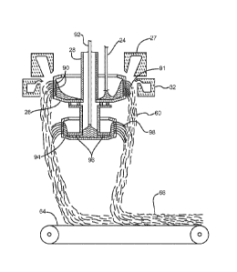
distributed throughout the fibrous product. This is important in contributing
to the
improved thermal resistivity, since it has been found that opacifying agents
applied to the
surface of a fibrous product penetrate only a short distance into the matrix,
and are not as
effective in improving thermal resistivity as opacifier uniformly distributed
throughout
the matrix.
EXAMPLES
Example 1: Aqueous opacifying agent dispersions
[0063] An aqueous sizing composition is prepared having a polyvinylacrylic
film
forming resin such as DUROCET or COVINAX, and an alkoxysilane coupling agent
such as A174 and A1100. Suitable wetting agents or surfactants may be added as
well.
To this size composition is added Aquadag E colloidal graphite to a final
concentration
of about 4% by weight. This size is applied to glass fibers spun from a rotary
fiberizer by
spraying the veil below the spinner.
Example 2: Thermoset binder fibers
[0064] Thermoset binder having a dry weight composition of 76.2%
maltodextrin,
19% citric acid and 4.8% sodium hypophosphite, was prepared in varying
concentration
sample dispersions, including one with a solids content of 70%. Thermoset
fibers were
prepared from this 70% sample dispersion in the lab at room temperature using
a 6 inch
diameter plastic rotary spinner spun at 1200 rpm and having a single orifice
having a
diameter of 0.041 inches. Samples of the spun fiber were examined by scanning
electron
microscopy (SEM) and by transmitted light optical microscopy at 400X
magnification
with a digital filar eyepiece. The distribution of fiber diameters (100 pts)
was determined
to be as set forth in Table 1, below.
21
CA 02828321 2013-08-23
WO 2012/135445
PCT/US2012/031127
Table 1: Thermoset fiber diameters
Diameter % in each
( m) size category
1 to 3 15
3 to 5 25
5 to 7 21
7 to 9 11
9 to 11 9
11 to 13 6
13 to 15 5
>15 8
Total 100
Example 3: Fibrous products
[0065] The opacifying size composition of Example 1 is sprayed onto glass
fibers
spun down to form small sample handsheets of unbonded glass fibers. Thermoset
fibers
as prepared in Example 2 are then blown down onto the sample handsheet using a
low-
pressure annular blower located next to the spinner. The handsheet bearing the
thermoset
binder fibers is removed and a second unbonded handsheet is placed on top,
with the
thermoset binder fibers between the two unbonded handsheets. This sandwich is
placed
in a lab oven and cures to bond the two handsheets of opacified fibers
together into a
fibrous product.
Example 4: Glasswool fibrous products and conductivity
[0066] Glasswool samples were formed in a dual hole bushing from
bicomponent
fiber in a manner similar to the teachings of U.S. Patent 3,073,05 to Tiede,
which yields a
curly fiber, giving loft to the wool pack. A Vortek air amplifier pulls a
continuous fiber
from the bushing which is then collected by suction onto a screen. Triplicate
samples of
bare fiber (as control) and fibers substantially uniformly coated with either
carbon black
or graphite were prepared. The carbon black was applied by allowing a sooty
flame to be
pulled into the air amplifier along with the fiber to coat the fiber with
soot. The graphite
22
CA 02828321 2013-08-23
WO 2012/135445
PCT/US2012/031127
(Aquadag E from Henkel Corporation) was applied as a 0.5% to 1% water
suspension to
a pad which contacted the fiber above the air amplifier.
[0067] These glasswool samples were then packed into an 8" diameter
cylindrical
space cut from standard R4.2 hindered glass wool insulation (approximately
1.25 inches
thick) at a density close to that expected to yield an R value of 4.2. The
thermal
conductivity of each sample was measured according to ASTM C518 using a FOX
heat
flow instrument (from LaserComp, Saugus, MA) with a 4" by 4" meter area. This
procedure allows thermal measurements to be made on a relatively small sample.
[0068] The samples produced are described in Table 2 below. In each case
the wool
with the coating was fairly uniformly dark gray indicating the presence of a
reasonable
coating of the opacifier.
Table 2: Sample description
Sample # Sample description
1-3 bare glass; 2120 F bushing; 40 psi blower
5-7 soot addition; 2120 F bushing; 40 psi blower
9-11 graphite addition; 2120 F bushing; 25 psi blower
12-14 bare glass; 2120 F bushing; 25 psi blower
Note: Designations 4 and 8 are intentionally skipped.
[0069] The diameter of the glass wool fibers produced depends on the
bushing
temperature and the blower (air amplifier) pressure. Temperature remained
constant, but
blower pressure varied, creating fibers of differing diameters; samples 1-7
have a smaller
fiber diameter than samples 9-14. At equivalent mass densities and in the
diameter range
relevant here, smaller diameter fibers have more surface area to produce more
scattering
of thermal radiation and therefore improved thermal resistance/conductivity.
Consequently, samples 1-7 should not be compared directly with samples 9-14.
However, samples 1-3 may be compared with samples 5-7 to show the effect of
uniformly coated carbon black and samples 9-11 may be compared with samples 12-
14 to
show the effect of uniformly coated graphite on conductivity relative to bare
glass.
23
CA 02828321 2013-08-23
WO 2012/135445
PCT/US2012/031127
Example 5: Conductivity measurements on unbonded fibrous product
[0070] For the first set of measurements, the samples of Example 4,
unhindered in
any way, were stuffed as uniformly as possible into the cylindrical space in
the R4.2
insulation. Then the thermal conductivity was measured at three different
densities by
compressing the entire sample to different degrees. The results are displayed
in Figures
5A and 5B, which plot the conductivity against the density. The Y-axis plots
conductivity or "k-value" with units of BTU*in / heft2* F (abbreviated "k-
(BTU...)" in
the Figures.) Replicate samples, used to assess variability in the test, can
be identified
by identical X-axis density values.
[0071] Each sample shows the expected decrease in thermal conductivity with
increasing density, but there is some variability. The replicated soot sample
results
exhibit very similar conductivities, but the bare glass samples exhibit more
variability.
[0072] The data suggest that uniformly distributed carbon black reduces the
thermal
conductivity. The data further suggest that graphite may as well. The
unexpected
variability may be due to the unbonded, loose-fill nature of the insulation,
and the
difficulty in quantifying the density in the central 4" x 4" portion of the
sample which
dominates the thermal conductivity result.
Example 6: Conductivity measurements on bindered fibrous product
[0073] In an attempt to reduce the variability associated with loose-fill
glasswool
fibers, binder was applied to the packs to more accurately assess the density
of the central
4" x 4" part of the sample. For bare glass and soot-coated samples, this was
done by
mechanically dispersing a particulate thermoset binder throughout the sample
and
vibrating the sample, confining the sample in the 8" diameter x 1.25" high
cylindrical
space, and heat treating at 300 F for 15 minutes to set the binder. This
yielded reasonably
well-defined wool packs for bare glass and soot-coated fibers, however it was
observed
24
CA 02828321 2013-08-23
WO 2012/135445
PCT/US2012/031127
that the density was not uniform from top to bottom, with bottom density being
higher
and the rest of the pack having a lighter density. This has a detrimental
effect on thermal
conductivity of the sample relative to one having a uniform density.
[0074] For the three graphite-coated samples, the binder did not adhere
well so a
different approach was used. The graphite-coated fibers were heated to 752 F
for at least
15 minutes, which is sufficient to allow the glass fiber to relax slightly and
assume the
shape to which it is confined. The density uniformity of the graphite-coated
packs was
acceptably uniform.
[0075] The packs were then assessed for conductivity as in Example 5. The
results
are displayed in Figures 6A and 6B, which plot the conductivity against the
density. The
Y-axis plots conductivity or "k-value" with units of BTU*in / hr*ft2*0F
(abbreviated "k-
(BTU...)" in the Figures.)
[0076] These results suggest that both the soot and graphite opacifier
coatings
reduced the thermal conductivity compared to bare glass, with the effect of
graphite being
greater than the soot. It is unknown, however, to what degree the conductivity
performance of the graphite-coated fibers benefited from the more homogeneous
density
properties.
[0077] The principle and mode of operation of this invention have been
described in
its preferred embodiments. However, it should be noted that this invention may
be
practiced otherwise than as specifically illustrated and described without
departing from
its scope.