Note: Descriptions are shown in the official language in which they were submitted.
CA 2828917 2017-03-16
METHODS OF VARYING LOW EMISSION TURBINE GAS RECYCLE CIRCUITS
AND SYSTEMS AND APPARATUS RELATED THERETO
CROSS REFERENCE TO RELATED APPLICATIONS
100011 This application claims priority to U.S. Provisional Application
61/466,381 filed
March 22, 2011 entitled, METHODS OF VARYING LOW EMISSION TURBINE GAS
RECYCLE CIRCUITS AND SYSTEMS AND APPARATUS RELATED THERETO; U.S.
Provisional Application 61/542,035 filed September 30, 2011 entitled, METHODS
OF
VARYING LOW EMISSION TURBINE GAS RECYCLE CIRCUITS AND SYSTEMS
AND APPARATUS RELATED THERETO.
100021 This application is related to U.S. Provisional Application
61/542,036 filed
September 30, 2011 entitled, SYSTEMS AND METHODS FOR CARBON DIOXIDE
CAPTURE IN LOW EMISSION TURBINE SYSTEMS; U.S. Provisional Application
61/542,037 filed September 30, 2011 entitled, SYSTEMS AND METHODS FOR CARBON
DIOXIDE CAPTURE IN LOW EMISSION TURBINE SYSTEMS; U.S. Provisional
Application 61/542,039 filed September 30, 2011 entitled, SYSTEMS AND METHODS
FOR CARBON DIOXIDE CAPTURE IN LOW EMISSION COMBINED TURBINE
SYSTEMS; U.S. Provisional Application 61/542,041 filed September 30, 2011
entitled,
LOW EMISSION POWER GENERATION SYSTEMS AND METHODS
INCORPORATING CARBON DIOXIDE SEPARATION; U.S. Provisional Application
61/466,384 filed March 22, 2011 entitled, LOW EMISSION TURBINE SYSTEMS
HAVING A MAIN AIR COMPRESSOR OXIDANT CONTROL APPARATUS AND
METHODS RELATED THERETO; U.S. Provisional Application 61/542,030 filed
September 30, 2011 entitled, LOW EMISSION TURBINE SYSTEMS INCORPORATING
INLET COMPRESSOR OXIDANT CONTROL APPARATUS AND METHODS
RELATED THERETO; U.S. Provisional Application 61/466,385 filed March 22, 2011
entitled, METHODS FOR CONTROLLING STOICHIOMETRIC COMBUSTION ON A
FIXED GEOMETRY GAS TURBINE SYSTEM AND APPARATUS AND SYSTEMS
RELATED THERETO; U.S. Provisional Application 61/542,031 filed September 30,
2011
entitled, SYSTEMS AND METHODS FOR CONTROLLING STOICHIOMETRIC
COMBUSTION IN LOW EMISSION TURBINE SYSTEMS.
- 1 -
CA 2828917 2017-03-16
FIELD OF THE DISCLOSURE
[0003] Embodiments of the disclosure relate to low emission power
generation. More
particularly, embodiments of the disclosure relate to methods and apparatus
for varying low
emission turbine gas recycle circuits.
BACKGROUND OF THE DISCLOSURE
100041 This section is intended to introduce various aspects of the art,
which may be
associated with exemplary embodiments of the present disclosure. This
discussion is
believed to assist in providing a framework to facilitate a better
understanding of particular
aspects of the present disclosure. Accordingly, it should be understood that
this section
should be read in this light, and not necessarily as admissions of prior art.
100051 Many oil producing countries are experiencing strong domestic
growth in power
demand and have an interest in enhanced oil recovery (EOR) to improve oil
recovery from
their reservoirs. Two common EOR techniques include nitrogen (N2) injection
for reservoir
pressure maintenance and carbon dioxide (CO2) injection for miscible flooding
for EOR.
There is also a global concern regarding green house gas (GHG) emissions. This
concern
combined with the implementation of cap-and-trade policies in many countries
makes
reducing CO, emissions a priority for those countries as well as for the
companies that
operate hydrocarbon production systems therein.
[0006] Some approaches to lower CO2 emissions include fuel de-carbonization
or post-
combustion capture using solvents, such as amines. However, both of these
solutions are
expensive and reduce power generation efficiency, resulting in lower power
production,
increased fuel demand and increased cost of electricity to meet domestic power
demand. In
particular, the presence of oxygen, S0x, and NOx components makes the use of
amine
solvent absorption very problematic. Another approach is an oxyfuel gas
turbine in a
combined cycle (e.g., where exhaust heat from the gas turbine Brayton cycle is
captured to
make steam and produce additional power in a Rankin cycle). However, there are
no
commercially available gas turbines that can operate in such a cycle and the
power required
to produce high purity oxygen significantly reduces the overall efficiency of
the process.
[0007] Moreover, with the growing concern about global climate change and
the impact
of carbon dioxide emissions, emphasis has been placed on minimizing carbon
dioxide
- 2 -
CA 02828417 2013-08-27
WO 2012/128924 PCT/US2012/027770
emissions from power plants. Gas turbine combined cycle power plants are
efficient and
have a lower cost compared to nuclear or coal power generation technologies.
Capturing
carbon dioxide from the exhaust of a gas turbine combined cycle power plant is
very
expensive for the following reasons: (a) the low concentration of carbon
dioxide in the
exhaust stack, (b) the large volume of gas that needs to be treated, (c) the
low pressure of the
exhaust stream, and the large amount of oxygen that is present in the exhaust
stream. All of
these factors result in a high cost of carbon dioxide capture from combined
cycle plants.
[0008] Accordingly, there is still a substantial need for a low emission,
high efficiency
power generation and CO2 capture manufacturing process.
SUMMARY OF THE DISCLOSURE
[0009] In the combined cycle power plants described herein, exhaust gases
from low
emission gas turbines, which are vented in a typical natural gas combined
cycle (NGCC)
plant, are instead cooled and recycled to the gas turbine main compressor
inlet. The recycle
exhaust gases, rather than excess compressed fresh air, are used to cool the
products of
combustion down to the material limitations in the expander. The combustion
may be
stoichiometric or non-stoichiometric. In one or more embodiments, by combining
stoichiometric combustion with exhaust gas recycle, the concentration of CO,
in the
recirculating gases is increased while minimizing the presence of excess 02,
both of which
make CO2 recovery easier.
[0010] In one or more embodiments herein, methods are provided for varying
the exhaust
gas recycle circuit of such low emission gas turbine systems and apparatus
related thereto.
These methods improve the operability and cost effectiveness of low emission
gas turbine
operation. The methods, apparatus, and systems consider: (a) alternatives to
using a direct
contact cooler, which is a large and capital intensive piece of equipment, and
(b) methods and
apparatus for reducing erosion or corrosion on the blades in the first few
sections of the main
compressor caused by condensation of acidic water droplets in the recycle gas
stream.
BRIEF DESCRIPTION OF THE DRAWINGS
[0011] The foregoing and other advantages of the present disclosure may
become
apparent upon reviewing the following detailed description and drawings of non-
limiting
examples of embodiments in which:
[0012] FIG. 1 depicts an integrated system for low emission power
generation and
enhanced CO, recovery according to one or more embodiments of the present
disclosure.
- 3 -
CA 02828417 2013-08-27
WO 2012/128924 PCT/US2012/027770
[0013] FIG. 2 depicts an integrated system for low emission power
generation and
enhanced CO2 recovery according to one or more embodiments of the present
disclosure
wherein the blower is downstream of the heat recovery steam generator (HRSG)
low pressure
boiler.
[0014] FIG. 3 depicts an integrated system for low emission power
generation and
enhanced CO2 recovery according to one or more embodiments of the present
disclosure
utilizing psychrometric cooling of the blower inlet.
[0015] FIG. 4 depicts an integrated system for low emission power
generation and
enhanced CO2 recovery according to one or more embodiments of the present
disclosure
utilizing cooling water coils in the HRSG.
[0016] FIG. 5 depicts an integrated system for low emission power
generation and
enhanced CO2 recovery according to one or more embodiments of the present
disclosure,
which eliminates the direct contact cooler (DCC) and saturates the inlet to
the recycle
compressor.
100171 FIG. 6 depicts an integrated system for low emission power
generation and
enhanced CO2 recovery according to one or more embodiments of the present
disclosure,
which eliminates the DCC and superheats the inlet to the recycle compressor.
[0018] FIG. 7A depicts an integrated system for low emission power
generation and
enhanced CO2 recovery according to one or more embodiments of the present
disclosure
incorporating glycol dehydration of the cooled recycle gas.
[0019] FIG. 7B illustrates the relationship between the pressure and the
external heat
source temperature in a triethylene glycol (TEG) regeneration system.
[0020] FIG. 7C illustrates the relationship between the ejector steam
load and the external
heat source temperature in a TEG regeneration system.
[0021] FIG. 8 depicts an integrated system for low emission power
generation and
enhanced CO2 recovery according to one or more embodiments of the present
disclosure
incorporating glycol dehydration of the cooled recycle gas with glycol
regeneration
integrated into the cooling unit.
[0022] FIG. 9 depicts an integrated system for low emission power
generation and
enhanced CO2 recovery according to one or more embodiments of the present
disclosure
- 4 -
CA 02828417 2013-08-27
WO 2012/128924 PCT/US2012/027770
incorporating glycol dehydration of the cooled recycle gas with glycol
regeneration and a
desuperheater integrated into the cooling unit.
[0023] FIG. 10 depicts an integrated system for low emission power
generation and
enhanced CO2 recovery according to one or more embodiments of the present
disclosure
incorporating a feed/effluent cross exchanger across the recycle gas cooling
equipment.
DETAILED DESCRIPTION
[0024] In the following detailed description section, the specific
embodiments of the
present disclosure are described in connection with preferred embodiments.
However, to the
extent that the following description is specific to a particular embodiment
or a particular use
of the present disclosure, this is intended to be for exemplary purposes only
and simply
provides a description of the exemplary embodiments. Accordingly, the
disclosure is not
limited to the specific embodiments described below, but rather, it includes
all alternatives,
modifications, and equivalents falling within the true spirit and scope of the
appended claims.
[0025] Various terms as used herein are defined below. To the extent a
term used in a
claim is not defined below, it should be given the broadest definition persons
in the pertinent
art have given that term as reflected in at least one printed publication or
issued patent.
[0026] As used herein, the term "natural gas" refers to a multi-component
gas obtained
from a crude oil well (associated gas) and/or from a subterranean gas-bearing
formation (non-
associated gas). The composition and pressure of natural gas can vary
significantly. A
typical natural gas stream contains methane (CH4) as a major component, i.e.
greater than 50
mol% of the natural gas stream is methane. The natural gas stream can also
contain ethane
(C2H6), higher molecular weight hydrocarbons (e.g., C3-C20 hydrocarbons), one
or more acid
gases (e.g., hydrogen sulfide), or any combination thereof. The natural gas
can also contain
minor amounts of contaminants such as water, nitrogen, iron sulfide, wax,
crude oil, or any
combination thereof.
[0027] As used herein, the term "stoichiometric combustion" refers to a
combustion
reaction having a volume of reactants comprising a fuel and an oxidizer and a
volume of
products formed by combusting the reactants where the entire volume of the
reactants is used
to form the products. As used herein, the term "substantially stoichiometric
combustion"
refers to a combustion reaction having an equivalence ratio ranging from about
0.9:1 to about
1.1:1, or more preferably from about 0.95:1 to about 1.05:1.
- 5 -
CA 02828417 2013-08-27
WO 2012/128924 PCT/US2012/027770
[0028] As used herein, the term "stream" refers to a volume of fluids,
although use of the
term stream typically means a moving volume of fluids (e.g., having a velocity
or mass flow
rate). The term "stream," however, does not require a velocity, mass flow
rate, or a particular
type of conduit for enclosing the stream.
[0029] Embodiments of the presently disclosed systems and processes may be
used to
produce ultra low emission electric power and CO? for applications such as
enhanced oil
recovery (EOR) or sequestration. According to embodiments disclosed herein, a
mixture of
air and fuel can be combusted and simultaneously mixed with a stream of
recycled exhaust
gas. The stream of recycled exhaust gas, generally including products of
combustion such as
CO?, can be used as a diluent to control or otherwise moderate the temperature
of the
combustion and flue gas entering the succeeding expander.
[0030] The combustion may be stoichiometric or non-stoichiometric.
Combustion at near
stoichiometric conditions (or "slightly rich" combustion) can prove
advantageous in order to
eliminate the cost of excess oxygen removal. By cooling the flue gas and
condensing the
water out of the stream, a relatively high content CO2 stream can be produced.
While a
portion of the recycled exhaust gas can be utilized for temperature moderation
in the closed
Brayton cycle, a remaining purge stream can be used for EOR applications and
electric power
can be produced with little or no S0x, NOx, or CO2 being emitted to the
atmosphere. For
example, the purge stream can be treated in a CO2 separator adapted to
discharge a nitrogen-
rich gas which can be subsequently expanded in a gas expander to generate
additional
mechanical power. The result of the systems disclosed herein is the production
of power and
the manufacturing or capture of additional CO2 at a more economically
efficient level.
[0031] In one or more embodiments, the present invention is directed to
integrated
systems comprising a gas turbine system and an exhaust gas recirculation
system. The gas
turbine system comprises a combustion chamber configured to combust one or
more oxidants
and one or more fuels in the presence of a compressed recycle stream and an
exhaust gas
recirculation system. The combustion chamber directs a first discharge stream
to an expander
to generate a gaseous exhaust stream and at least partially drive a main
compressor, and the
main compressor compresses the gaseous exhaust stream and thereby generates
the
compressed recycle stream. The exhaust gas recirculation system comprises at
least one
cooling unit configured to receive and cool the gaseous exhaust stream and at
least one
blower configured to receive and increase the pressure of the gaseous exhaust
stream before
directing a cooled recycle gas to the main compressor.
- 6 -
CA 02828417 2013-08-27
WO 2012/128924 PCT/US2012/027770
[0032] In certain embodiments, the at least one cooling unit may be a
heat recovery steam
generator (HRSG) configured to receive and cool the gaseous exhaust stream
before
introduction to the at least one blower. In the same or other embodiments, the
exhaust gas
recirculation system may further comprise a second cooling unit configured to
receive the
gaseous exhaust stream from the at least one blower and further cool the
gaseous exhaust
stream to generate the cooled recycle gas. The second cooling unit may
comprise a direct
contact cooler (DCC) section. Alternately, the second cooling unit may
comprise a HRSG.
[0033] In some embodiments, the exhaust gas recirculation system may
further comprise
a third cooling unit configured to receive the gaseous exhaust stream from the
at least one
blower and further cool the gaseous exhaust stream before introduction to the
second cooling
unit. In such embodiments, the first cooling unit and the third cooling unit
may comprise
HRSGs. In one or more embodiments, the first cooling unit may comprise a HRSG
comprising a high pressure boiler section, an intermediate pressure boiler
section, and a low
pressure boiler section, and the third cooling unit may comprise a HRSG
comprising a low
pressure boiler section and an economizer section.
[0034] In some embodiments, one or more HRSGs employed in the exhaust gas
recirculation system may further comprise cooling water coils. In such
embodiments, the
system may further comprise a separator configured to receive the gaseous
exhaust stream
from the cooling water coils of the HRSG and remove water droplets from the
gaseous
exhaust stream before introduction to the blower or main compressor. In one or
more
embodiments, the separator is a vane pack, mesh pad, or other demisting
device.
[0035] In one or more embodiments of the present invention, the exhaust
gas
recirculation system may employ psychrometric cooling of the gaseous exhaust
stream. In
some embodiments, water is added to the gaseous exhaust stream to saturate or
nearly
saturate the gaseous exhaust stream downstream of the first cooling unit but
before
introduction to the blower, and the exhaust gas recirculation system further
comprises a
separator configured to receive the saturated or nearly saturated gaseous
exhaust stream and
remove water droplets from the saturated or nearly saturated gaseous exhaust
stream before
introduction to the blower. In such embodiments, the second cooling unit is
further
configured to remove water from the gaseous exhaust stream and recycle at
least part of the
water removed. The water removed from the gaseous exhaust stream by the second
cooling
unit may be divided into two or more portions, such that a first portion of
the water is
- 7 -
CA 02828417 2013-08-27
WO 2012/128924 PCT/US2012/027770
recycled and added to the gaseous exhaust stream upstream of the separator and
a second
portion of the water is recycled to the second cooling unit.
[0036] In one or more embodiments, the exhaust gas recirculation system
may further
comprise a feed/effluent cross exchanger across the second cooling unit
configured to adjust
the temperature of the cooled recycle gas such that a dew point margin of at
least about 20 F,
or at least about 25 F, or at least about 30 F, or at least about 35 F, or
at least about 40 F,
or at least about 45 F, or at least about 50 F is achieved.
[0037] In one or more embodiments, the second cooling unit further
comprises a glycol
absorption section, such as for example a triethylene glycol (TEG) absorption
section,
configured to receive the cooled recycle gas from the upstream recycle gas
cooling
equipment and at least partially dehydrate the cooled recycle gas before
introduction to the
main compressor, and the exhaust gas recirculation system further comprises a
glycol
regeneration system configured to receive rich glycol from the glycol
absorption section of
the second cooling unit, thermally regenerate the rich glycol in a glycol
regeneration column
to form regenerated lean glycol, and return the regenerated lean glycol to the
glycol
absorption section. In some embodiments, the glycol regeneration system is
operated under
vacuum conditions. The glycol regeneration system may be separate from or
integrated into
the second cooling unit. In one or more embodiments, the second cooling unit
comprises the
glycol regeneration column and the glycol regeneration column is configured to
receive the
gaseous exhaust stream from the blower before introduction to the upstream
recycle gas
cooling equipment. In the same or other embodiments, the second cooling unit
may further
comprise a desuperheating section positioned between the glycol regeneration
column and
the upstream recycle gas cooling equipment. Any suitable glycol may be used in
the glycol
absorption systems described herein. For example, in one or more embodiments
the glycol is
triethylene glycol (TEG). Further, in one or more other embodiments of the
present
invention, another suitable method for dehydrating the cooled recycle gas may
be employed
in place of glycol dehydration, such as for example mole sieves or methanol
dehydration.
[0038] In one or more embodiments, the present invention is directed to
methods of
generating power. The methods comprise combusting at least one oxidant and at
least one
fuel in a combustion chamber in the presence of a compressed recycle exhaust
gas, thereby
generating a discharge stream, expanding the discharge stream in an expander
to at least
partially drive a main compressor and generate a gaseous exhaust stream, and
directing the
gaseous exhaust stream to an exhaust gas recirculation system. The main
compressor
- 8 -
CA 02828417 2013-08-27
WO 2012/128924 PCT/US2012/027770
compresses the gaseous exhaust stream and thereby generates the compressed
recycle stream.
In such methods, the exhaust gas recirculation system comprises at least one
cooling unit and
at least one blower, such that the gaseous exhaust stream is cooled in at the
least one cooling
unit and the pressure of the gaseous exhaust stream is increased in the at
least one blower,
thereby generating a cooled recycle gas directed to the main compressor.
[0039] In one or more methods of the present invention, the at least one
cooling unit is a
direct contact cooler (DCC), heat recovery steam generator (HRSG), or other
suitable cooling
device that cools the gaseous exhaust stream before the gaseous exhaust stream
is introduced
to the at least one blower. In the same or other methods, the exhaust gas
recirculation system
further comprises a second cooling unit that receives the gaseous exhaust
stream from the at
least one blower and further cools the gaseous exhaust stream, thereby
generating the cooled
recycle gas. The second cooling unit may comprise a DCC, a HRSG, or other
suitable
cooling device.
[0040] In some methods, the exhaust gas recirculation system may further
comprise a
third cooling unit that receives the gaseous exhaust stream from the at least
one blower and
further cools the gaseous exhaust stream before the gaseous exhaust stream is
introduced to
the second cooling unit. In one or more methods, the first cooling unit and
the third cooling
unit comprise HRSGs. In the same or other methods, the first cooling unit may
comprise a
HRSG comprising a high pressure boiler section, an intermediate pressure
boiler section, and
a low pressure boiler section, and the third cooling unit may comprise a HRSG
comprising a
low pressure boiler section and an economizer section.
[0041] In some methods, one or more of the HRSGs employed in the exhaust
gas
recirculation system may further comprise cooling water coils. In such
methods, a separator
may receive the gaseous exhaust stream from the cooling water coils of the
HRSG and
remove water droplets from the gaseous exhaust stream before the gaseous
exhaust stream is
introduced to the blower or main compressor. In one or more embodiments, the
separator is a
vane pack, mesh pad, or other demisting device.
[0042] In one or more methods of the present invention, the exhaust gas
recirculation
system employs psychrometric cooling to further cool the gaseous exhaust
stream. In some
of those methods, the gaseous exhaust stream is saturated or nearly saturated
with water
before the gaseous exhaust stream is introduced to the blower, the exhaust gas
recirculation
system further comprises a separator that receives the saturated or nearly
saturated gaseous
- 9 -
CA 02828417 2013-08-27
WO 2012/128924 PCT/US2012/027770
exhaust stream and removes water droplets from the saturated or nearly
saturated gaseous
exhaust stream before the gaseous exhaust stream is introduced to the blower,
and the second
cooling unit removes water from the gaseous exhaust stream and at least part
of the water
removed by the second cooling unit is recycled. In one or more methods, the
water removed
from the gaseous exhaust stream by the second cooling unit is divided into two
or more
portions and a first portion of the water is recycled and added to the gaseous
exhaust stream
upstream of the separator while a second portion of the water is recycled to
the second
cooling unit.
[0043] In one or more embodiments of the present invention, a dew point
margin of at
least about 20 F, or at least about 25 F, or at least about 30 F, or at
least about 35 F, or at
least about 40 F, or at least about 45 F, or at least about 50 F is
achieved in the cooled
recycle gas by modifying the temperature of the cooled recycle gas in a
feed/effluent cross
exchanger across the second cooling unit.
[0044] In one or more methods of the present invention, the second
cooling unit further
comprises a glycol absorption section that receives the cooled recycle gas
from the upstream
recycle gas cooling equipment and at least partially dehydrates the cooled
recycle gas before
the cooled recycle gas is introduced to the main compressor, and the exhaust
gas recirculation
system further comprises a glycol regeneration system that receives rich
glycol from the
glycol absorption section of the second cooling unit, thermally regenerates
the rich glycol in a
glycol regeneration column to form regenerated lean glycol, and returns the
regenerated lean
glycol to the glycol absorption section. In some methods, the glycol
regeneration system is
operated under vacuum conditions. The glycol regeneration system may be
separate from or
integrated into the second cooling unit. Tn one or more methods, the second
cooling unit
comprises the glycol regeneration column and the glycol regeneration column
receives the
gaseous exhaust stream from the blower before the gaseous exhaust stream is
introduced to
the upstream recycle gas cooling equipment. In the same or other methods, the
second
cooling unit may further comprise a desuperheating section positioned between
the glycol
regeneration column and the upstream recycle gas cooling equipment that
receives the
gaseous exhaust stream from the glycol regeneration column and cools the
gaseous exhaust
stream to a temperature sufficient to at least partially condense glycol from
the gaseous
exhaust stream before the gaseous exhaust stream is introduced to the upstream
recycle gas
cooling equipment.
- 10 -
CA 02828417 2013-08-27
WO 2012/128924 PCT/US2012/027770
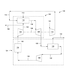
[0045] Referring now to the figures, FIG. 1 illustrates a power
generation system 100
configured to provide an improved post-combustion CO2 capture process. In at
least one
embodiment, the power generation system 100 can include a gas turbine system
102 that can
be characterized as a closed Brayton cycle. In one embodiment, the gas turbine
system 102
can have a first or main compressor 104 coupled to an expander 106 through a
common shaft
108 or other mechanical, electrical, or other power coupling, thereby allowing
a portion of
the mechanical energy generated by the expander 106 to drive the compressor
104. The
expander 106 may generate power for other uses as well, such as to power a
second or inlet
compressor 118. The gas turbine system 102 can be a standard gas turbine,
where the main
compressor 104 and expander 106 form the compressor and expander ends,
respectively, of
the standard gas turbine. In other embodiments, however, the main compressor
104 and
expander 106 can be individualized components in a system 102.
[0046] The gas turbine system 102 can also include a combustion chamber
110
configured to combust a fuel stream 112 mixed with a compressed oxidant 114.
In one or
more embodiments, the fuel stream 112 can include any suitable hydrocarbon gas
or liquid,
such as natural gas, methane, naphtha, butane, propane, syngas, diesel,
kerosene, aviation
fuel, coal derived fuel, bio-fuel, oxygenated hydrocarbon feedstock, or
combinations thereof.
The compressed oxidant 114 can be derived from a second or inlet compressor
118 fluidly
coupled to the combustion chamber 110 and adapted to compress a feed oxidant
120. In one
or more embodiments, the feed oxidant 120 can include any suitable gas
containing oxygen,
such as air, oxygen-rich air, or combinations thereof.
[0047] As will be described in more detail below, the combustion chamber
110 can also
receive a compressed recycle stream 144, including a flue gas primarily having
CO, and
nitrogen components. The compressed recycle stream 144 can be derived from the
main
compressor 104 and adapted to help facilitate the combustion of the compressed
oxidant 114
and fuel 112, and also increase the CO2 concentration in the working fluid. A
discharge
stream 116 directed to the inlet of the expander 106 can be generated as a
product of
combustion of the fuel stream 112 and the compressed oxidant 114, in the
presence of the
compressed recycle stream 144. In at least one embodiment, the fuel stream 112
can be
primarily natural gas, thereby generating a discharge 116 including volumetric
portions of
vaporized water, CO2, nitrogen, nitrogen oxides (N0x), and sulfur oxides
(S0x). In some
embodiments, a small portion of unburned fuel 112 or other compounds may also
be present
in the discharge 116 due to combustion equilibrium limitations. As the
discharge stream 116
- 11 -
CA 02828417 2013-08-27
WO 2012/128924 PCT/US2012/027770
expands through the expander 106 it generates mechanical power to drive the
main
compressor 104, or other facilities, and also produces a gaseous exhaust
stream 122 having a
heightened CO2 content.
[0048] The power generation system 100 can also include an exhaust gas
recirculation
(EGR) system 124. While the EGR system 124 illustrated in the figures
incorporates various
apparatus, the illustrated configurations are representative only and any
system that
recirculates the exhaust gas 122 back to the main compressor to accomplish the
goals stated
herein may be used. In one or more embodiments, the EGR system 124 can include
a heat
recovery steam generator (HRSG) 126, or similar device. The gaseous exhaust
stream 122
can be sent to the HRSG 126 in order to generate a stream of steam 130 and a
cooled exhaust
gas 132. The steam 130 can optionally be sent to a steam gas turbine (not
shown) to generate
additional electrical power. In such configurations, the combination of the
HRSG 126 and
the steam gas turbine can be characterized as a closed Rankine cycle. In
combination with
the gas turbine system 102, the HRSG 126 and the steam gas turbine can form
part of a
combined-cycle power generating plant, such as a natural gas combined-cycle
(NGCC) plant.
[0049] FIG. 1 illustrates additional apparatus in the EGR system 124 that
may be
incorporated in some embodiments. The cooled exhaust gas 132 can be sent to at
least one
cooling unit 134 configured to reduce the temperature of the cooled exhaust
gas 132 and
generate a cooled recycle gas stream 140. In one or more embodiments, the
cooling unit 134
is considered herein to be a direct contact cooler (DCC), but may be any
suitable cooling
device such as a direct contact cooler, trim cooler, a mechanical
refrigeration unit, or
combinations thereof. The cooling unit 134 can also be configured to remove a
portion of
condensed water via a water dropout stream (not shown). In one or more
embodiments, the
cooled exhaust gas stream 132 can be directed to a blower or boost compressor
142 fluidly
coupled to the cooling unit 134. In such embodiments, compressed exhaust gas
stream 136
exits the blower 142 and is directed to the cooling unit 134.
[0050] The blower 142 can be configured to increase the pressure of the
cooled exhaust
gas stream 132 before it is introduced into the main compressor 104. In one or
more
embodiments, the blower 142 increases the overall density of the cooled
exhaust gas stream
132, thereby directing an increased mass flow rate for the same volumetric
flow to the main
compressor 104. Because the main compressor 104 is typically volume-flow
limited,
directing more mass flow through the main compressor 104 can result in a
higher discharge
pressure from the main compressor 104, thereby translating into a higher
pressure ratio across
- 12 -
CA 02828417 2013-08-27
WO 2012/128924 PCT/US2012/027770
the expander 106. A higher pressure ratio generated across the expander 106
can allow for
higher inlet temperatures and, therefore, an increase in expander 106 power
and efficiency.
This can prove advantageous since the CO2-rich discharge 116 generally
maintains a higher
specific heat capacity. Accordingly, the cooling unit 134 and the blower 142,
when
incorporated, may each be adapted to optimize or improve the operation of the
gas turbine
system 102. It should be noted that, although the blower 142 is shown in a
particular location
in the EGR system 124 in FIG. 1 and in the other drawings and examples
described herein,
the blower may be located anywhere throughout the recycle loop.
[0051] The main compressor 104 can be configured to compress the cooled
recycle gas
stream 140 received from the EGR system 124 to a pressure nominally above the
combustion
chamber 110 pressure, thereby generating the compressed recycle stream 144. In
at least one
embodiment, a purge stream 146 can be tapped from the compressed recycle
stream 144 and
subsequently treated in a CO2 separator or other apparatus (not shown) to
capture CO2. The
separated CO2 can be used for sales, used in another process requiring carbon
dioxide, and/or
compressed and injected into a terrestrial reservoir for enhanced oil recovery
(EOR),
sequestration, or another purpose.
[0052] The EGR system 124 as described herein can be implemented to
achieve a higher
concentration of CO2 in the working fluid of the power generation system 100,
thereby
allowing for more effective CO2 separation for subsequent sequestration,
pressure
maintenance, or EOR applications. For instance, embodiments disclosed herein
can
effectively increase the concentration of CO2 in the flue gas exhaust stream
to about 10 wt%
or higher. To accomplish this, the combustion chamber 110 can be adapted to
stoichiometrically combust the incoming mixture of fuel 112 and compressed
oxidant 114. In
order to moderate the temperature of the stoichiometric combustion to meet
expander 106
inlet temperature and component cooling requirements, a portion of the exhaust
gas derived
from the compressed recycle stream 144 can be injected into the combustion
chamber 110 as
a diluent. Thus, embodiments of the disclosure can essentially eliminate any
excess oxygen
from the working fluid while simultaneously increasing its CO2 composition. As
such, the
gaseous exhaust stream 122 can have less than about 3.0 vol% oxygen, or less
than about 1.0
vol% oxygen, or less than about 0.1 vol% oxygen, or even less than about 0.001
vol%
oxygen. In some implementations, the combustion chamber 110, or more
particularly, the
inlet streams to the combustion chamber may be controlled with a preference to
- 13 -
CA 02828417 2013-08-27
WO 2012/128924 PCT/US2012/027770
substoichiometric combustion to further reduce the oxygen content of the
gaseous exhaust
stream 122.
100531 In some embodiments not depicted herein, high pressure steam may
also be
employed as a coolant in the combustion process, either in place of or in
addition to the
recycled exhaust gas. In such embodiments, the addition of steam would reduce
power and
size requirements in the EGR system (or eliminate the EGR system altogether),
but would
require the addition of a water recycle loop.
100541 Additionally, in further embodiments not depicted herein, the
compressed oxidant
feed to the combustion chamber may comprise argon. For example, the oxidant
may
comprise from about 0.1 to about 5.0 vol% argon, or from about 1.0 to about
4.5 vol% argon,
or from about 2.0 to about 4.0 vol% argon, or from about 2.5 to about 3.5 vol%
argon, or
about 3.0 vol% argon. In such embodiments, the operation of the combustion
chamber may
be stoichiometric or non-stoichiometric. As will be appreciated by those
skilled in the an,
incorporating argon into the compressed oxidant feed may require the addition
of a cross
exchanger or similar device between the main compressor and the combustion
chamber
configured to remove excess CO2 from the recycle stream and return argon to
the combustion
chamber at the appropriate temperature for combustion.
[0055] As can be appreciated, specific temperatures and pressures
achieved or
experienced in the various components of any of the embodiments disclosed
herein can
change depending on, among other factors, the purity of the oxidant used and
the specific
makes and/or models of expanders, compressors, coolers, etc. Accordingly, it
will be
appreciated that the particular data described herein is for illustrative
purposes only and
should not be construed as the only interpretation thereof. For example, in
one exemplary
embodiment herein, the HRSG 126 cools the exhaust gas stream 132 to
approximately
200 F. Exhaust gas stream 132 is boosted in pressure by the blower 142 in
order to
overcome the downstream pressure drop, resulting in a temperature increase
such that cooled
compressed exhaust gas stream 136 exits the blower 142 at approximately 229
F. The
exhaust gas is further cooled in the cooling unit 134, and cooled recycle gas
stream 140 exits
the cooling unit 134 at approximately 100 F.
[0056] Referring now to FIG. 2, depicted is an alternative embodiment of
the power
generation system 100 of FIG. 1, embodied and described as system 200. As
such, FIG. 2
may be best understood with reference to FIG. 1. Similar to the system 100 of
FIG. 1, the
- 14 -
CA 02828417 2013-08-27
WO 2012/128924 PCT/US2012/027770
system 200 of FIG. 2 includes a gas turbine system 102 coupled to or otherwise
supported by
an exhaust gas recirculation (EGR) system 124. The EGR system 124 in FIG. 2,
however,
can include a second HRSG 202 downstream of the blower 142 to recover the heat
of
compression associated with the blower 142. In one or more embodiments
exemplified by
the EGR system of FIG. 2, the first HRSG 126 is a triple pressure HRSG
including high
pressure (HP), intermediate pressure (IP) and low pressure (LP) boiler
sections, while the
second HRSG 202 includes LP boiler and economizer sections. In an exemplary
method of
operation of system 200, the exhaust gas stream 132 exits the LP boiler
section of HRSG 126
at a temperature of approximately 279 F and is compressed in the blower 142.
Cooled
compressed exhaust gas stream 136 exits the blower 142 at a temperature of
about 310 F,
and enters the second HRSG 202. Recycle gas stream 138 then exits the second
HRSG 202
at a temperature of approximately 200 F. In this manner, the blower heat of
compression is
recovered by HRSG 202 and the cooling duty of the cooling unit 134 is reduced.
100571 FIG. 3 depicts another embodiment of the low emission power
generation system
100 of FIG. 1, embodied as system 300. As such, FIG. 3 may be best understood
with
reference to FIG. 1. Similar to the system 100 described in FIG. 1, the system
300 includes a
gas turbine system 102 supported by or otherwise coupled to an EGR system 124.
The EGR
system 124 in FIG. 3, however, employs psychrometric cooling to reduce power
consumption
of the blower 142 and reduce the cooling duty of the cooling unit 134. In one
or more
embodiments exemplified by the EGR system of FIG. 3, water is injected via
stream 302 to
saturate or nearly saturate and cool exhaust gas stream 132, resulting in a
saturated exhaust
gas stream 304. Saturated exhaust gas stream 304 may optionally be directed to
a separator
306 to remove any water droplets that may be entrained therein. Separator 306
can be any
device suitable for the removal of water droplets, such as for example a vane
pack, mesh pad,
or other demisting device. The pressure of saturated exhaust gas stream 304 is
increased in
the blower 142. Cooled compressed exhaust gas stream 136 exits the blower 142
and is
directed to the cooling unit 134. In the cooling unit, water condenses out of
cooled
compressed exhaust gas stream 136 as the stream is further cooled, and the
water is recovered
in water stream 308. In one or more embodiments of the invention, water stream
308 may be
cooled in a heat exchanger 310 or other cooling device, resulting in cooled
water stream 312.
Cooled water stream 312 may then be recycled via recycle water stream 314 to
provide
additional cooling of the exhaust gas in the cooling unit 134, combined with
water stream 302
to be injected into exhaust gas stream 132 upstream of the blower 142, or
both. While water
- 15 -
CA 02828417 2013-08-27
WO 2012/128924 PCT/US2012/027770
stream 302 may be employed at some points during operation of the system of
FIG. 3, such
as for example during start-up or when makeup water is needed in the system,
it will be
apparent to those skilled in the art that there may be times (for example
during steady state
operation) that the amount of water required for injection into exhaust gas
stream 132 may be
supplied entirely by the recycle of cooled water stream 312.
100581 In an exemplary method of operation of system 300, the exhaust gas
stream 132
exits the HRSG 126 at a temperature of approximately 200 F. The injection of
water via
stream 302 cools the exhaust gas, resulting in saturated exhaust gas stream
304 having a
temperature of approximately 129 F. Once compressed in the blower 142, cooled
compressed exhaust gas stream 136 exits the blower 142 at a temperature of
about 154 F,
and is cooled in the cooling unit 134 resulting in cooled recycle gas stream
at a temperature
of approximately 100 F. In this manner, the blower adds less heat to the
system and the
cooling duty of the cooling unit 134 is reduced.
[0059] FIG. 4 depicts another embodiment of the low emission power
generation system
100 of FIG. 1, embodied as system 400. FIG. 4 may be best understood with
reference to
FIGs. 1 and 3. Similar to the system 100 described in FIG. 1, the system 400
includes a gas
turbine system 102 supported by or otherwise coupled to an EGR system 124. The
EGR
system 124 in FIG. 4, however, employs cooling water coils in the HRSG to
reduce the
cooling duty of the cooling unit 134. In one or more embodiments exemplified
by the EGR
system of FIG. 3, cooling water coils 402 are employed within the HRSG 126 to
provide
additional cooling of exhaust gas stream 122. The cooling water coils may be
adapted to
employ fresh cooling water or seawater. To use fresh cooling water, in some
embodiments a
closed fresh water system may be included in the design (not shown), with
plate and frame
exchangers that cool the fresh water against seawater to achieve maximum
cooling. If
seawater coils are used in the HRSG, the HRSG tubes should be of sufficient
metallurgy to
handle both potential acidic water condensation and seawater. Cooled exhaust
gas stream
132 exits the HRSG 126 and may optionally be directed to a separator 306 to
remove any
water droplets that may be entrained therein. Separator 306 can be any device
suitable for the
removal of water droplets, such as for example a vane pack, mesh pad, or other
demisting
device. Once any entrained water droplets are removed by separator 306, the
cooled exhaust
gas stream 132 is directed to the blower 142 and the EGR system downstream of
the blower
is as previously described with respect to FIG. 1.
- 16 -
CA 02828417 2013-08-27
WO 2012/128924 PCT/US2012/027770
[0060] In an exemplary method of operation of system 400, cooled exhaust
gas stream
132 exits the cooling water coils 402 of HRSG 126 at a temperature of
approximately 118 F,
and compressed exhaust gas stream 136 exits the blower 142 at a temperature of
approximately 140 F. The exhaust gas is cooled in the cooling unit 134, and
cooled recycle
gas stream 140 exits the cooling unit 134 at approximately 100 F. Because the
compressed
exhaust gas stream 136 in the system 400 of FIG. 4 enters the cooling unit 134
at a lower
temperature than in the previously described systems of FIGs. 1-3, the duty of
the cooling
unit is reduced with respect to those systems.
[0061] FIG. 5 depicts another embodiment of the low emission power
generation system
100 of FIG. 1, embodied as system 500. FIG. 5 may be best understood with
reference to
FIGs. 1 and 4. Similar to the system 100 described in FIG. 1, the system 500
includes a gas
turbine system 102 supported by or otherwise coupled to an EGR system 124. The
EGR
system 124 in FIG. 5 employs cooling water coils 402 in the HRSG 126 and a
separator 306
upstream of the blower 142 as described in detail with respect to FIG. 4. FIG.
5, however,
also employs an additional HRSG 502 downstream of the blower 142, replacing
the direct
contact cooler (DCC) cooling unit described previously with respect to FIGS. 1-
4. The
HRSG 502 includes a cooling water section similar to the cooling water coils
402 contained
within the first HRSG 126. A separator section 504 is also included within the
additional
HRSG 502 to remove any condensed water droplets from the compressed exhaust
gas stream
136. Separator section 504 can be any device suitable for the removal of water
droplets, such
as for example a vane pack, mesh pad, or other demisting device. Once any
water droplets
are removed by separator section 504 within the additional HRSG 502, cooled
recycle gas
stream 140 exits the HRSG 502 and is recycled directly to the main compressor
104.
[0062] In an exemplary method of operation of system 500, cooled exhaust
gas stream
132 exits the cooling water coils 402 of the first HRSG 126 at a temperature
of approximately
113 F, and compressed exhaust gas stream 136 exits the blower 142 at a
temperature of
approximately 143 F. The exhaust gas is further cooled in the second HRSG
502, and
cooled recycle gas stream 140 exits the separator section 504 of the second
HRSG at
approximately 113 F. In one or more embodiments according to FIG. 5, the
cooled recycle
gas stream 140 entering the main compressor 104 is saturated with water.
[0063] In one or more of the embodiments depicted by FIGs. 1 through 5,
the cooled
recycle gas stream 140 may be saturated with water. Accordingly, there is a
risk that acidic
water droplets may form in the stream and cause erosion or corrosion of the
blades of main
- 17 -
CA 02828417 2013-08-27
WO 2012/128924 PCT/US2012/027770
compressor 104. FIG. 6 depicts another embodiment of the low emission power
generation
system 100 of FIG. 1, embodied as system 600, which is configured to reduce or
eliminate
the formation of acidic water droplets by superheating the recycle gas stream
entering the
main compressor 104. FIG. 6 may be best understood with reference to FIGs. 1,
4, and 5.
Similar to the system 100 described in FIG. 1, the system 600 includes a gas
turbine system
102 supported by or otherwise coupled to an EGR system 124. Similar to the
system 400
described in FTG.4, the EGR system 124 in FIG. 6 also employs cooling water
coils 402 in
the HRSG 126 and a separator 306 upstream of the blower 142. The system of
FIG. 6,
however, eliminates the use of a cooling unit or other cooling device
downstream of the
blower 142 and upstream of the main compressor 104, instead directing
compressed exhaust
gas stream 136 directly from the blower 142 to the main compressor 104.
[0064] In an exemplary method of operation of system 600, cooled exhaust
gas stream
132 exits the cooling water coils 402 of the first HRSG 126 at a temperature
of approximately
113 F. Exhaust gas stream 132 is superheated by the heat of compression of
the blower 142,
and compressed exhaust gas stream 136 exits the blower 142 at a temperature of
approximately 144 F. In this manner, the configuration of FIG. 6 achieves
about 25 F of
superheating. As used herein, the term "superheating" refers to the extent to
which the
temperature of a gas is above the dew point temperature of that gas.
Accordingly, 25 F of
superheating means that the temperature of a gas is 25 F above its dew point
temperature.
Compressed exhaust gas stream 136 is routed directly to the main compressor
104 without
further cooling. If additional superheating of the gas stream is desired, such
additional
heating may be obtained by a variety of methods, such as for example by cross
exchanging
the blower discharge with flue gas upstream of the cooling water coils in the
HRSG (not
shown). Such a cross exchanger configuration would be similar to air
preheaters that are
commonly installed with furnaces or incinerators and would decrease the
required area of the
cooling water coils but would add the additional expense of a large cross
exchanger.
[0065] The configuration of system 600 in FIG. 6 is intended to reduce or
eliminate the
formation of acidic water droplets and prevent erosion or corrosion of the
blades of the main
compressor by superheating the recycle gas stream. FIGs. 7 through 9 depict
alternative
embodiments of the present invention also intended to reduce or eliminate the
formation of
acidic water droplets in the recycle gas stream by dehydrating the recycle gas
stream using
glycol, such as for example triethylene glycol (TEG). In order for such glycol
dehydration
configurations to be cost effective, waste heat is used to regenerate the
glycol. Waste heat
- 18 -
CA 02828417 2013-08-27
WO 2012/128924 PCT/US2012/027770
may be captured from a variety of sources in the system, such as from the back
of one or
more heat recovery steam generators (HRSGs) or from compression inter-cooling.
[0066] FIG. 7A depicts an embodiment of a portion of the EGR system 124
of a low
emission power generation system such as that depicted in FIG. 1, embodied as
system 700,
which is configured to reduce or eliminate the formation of acidic water
droplets by
dehydrating the recycle gas stream entering the main compressor using a glycol
contactor
section within the cooling unit and regenerating the glycol in a separate
glycol vacuum
regeneration system. FIG. 7A may be best understood with reference to FIG. 1.
In the
system 700, cooled exhaust gas stream 132 flows from the FIRSG 126 and is
directed to the
blower 142, where the stream is compressed. Compressed exhaust gas stream 136
exits the
blower 142 and is directed to the cooling unit 134, which in one or more
embodiments
comprises a direct contact cooler (DCC) section utilizing water as the cooling
medium. In
one or more embodiments, the cooling unit 134 is considered herein to be a
direct contact
cooler (DCC), but may be any suitable cooling device such as a direct contact
cooler, trim
cooler, a mechanical refrigeration unit, or combinations thereof. Within the
cooling unit 134,
the compressed exhaust gas stream 136 is contacted with water to cool the
stream. A water
dropout stream 702 exits the cooling unit after contacting the gas stream. In
one or more
embodiments, a portion of water dropout stream 702 may be purged from the
system 700,
while the remaining portion of the water dropout stream may be cooled using a
heat
exchanger 720 and recycled to the cooling unit 134 to provide further cooling
of the
compressed exhaust gas stream 136. In one or more embodiments, the heat
exchanger 720
utilizes seawater to provide the required cooling. In the same or other
embodiments,
additional cooling may be provided by a chilled water cooler (not shown)
installed
downstream of the heat exchanger 720 in order to counteract the temperature
rise associated
with dehydration that occurs within the cooling unit 134 when glycol
dehydration is
employed. The use of a chilled water cooler in this manner may be desirable
because by
lowering the temperature of the gas fed to the dehydration portion of the
process, the recycled
exhaust gas temperature is similarly lowered and the power consumption of the
blower and
main compressor are reduced. Persons of skill in the art will recognize that
the use of a
chilled water cooler may be desirable in any configuration employing glycol
dehydration,
including not only the configuration depicted by FIG. 7A but also those
depicted in FIGs. 8
and 9 and in any other dehydration system.
- 19 -
CA 02828417 2013-08-27
WO 2012/128924 PCT/US2012/027770
[0067] The cooling unit 134 further comprises a glycol absorption section
710. In one or
more embodiments, the glycol absorption section is an absorption column such
as a tray
column or a packed column. Once the compressed exhaust gas stream has been
cooled with
water, the gas enters the glycol absorption section 710 of the cooling unit
134, where water
vapor in the exhaust gas is absorbed by the glycol. The resulting cooled
recycle gas stream
140, which has been at least partially dehydrated by the glycol, exits the
cooling unit 134 and
is directed to the main compressor 104. Once the glycol has absorbed the water
from the
exhaust gas, it is withdrawn from the glycol absorption section 710 via rich
glycol stream 712
and is directed to a vacuum regeneration system 750.
[0068] Within the vacuum regeneration system 750, rich glycol stream 712 is
heated in a
cross exchanger 722 and fed to a glycol regeneration column 730, where the
glycol is
thermally regenerated. Regenerator overhead stream 736 exits the top of glycol
regeneration
column 730, while the regenerated glycol stream 732 exits the bottom of the
column and is
directed to a reboiler 734. From the reboiler 734, a glycol vapor stream 733
is returned to the
glycol regeneration column and lean glycol stream 714 is directed through the
cross
exchanger 722 and optionally one or more heat exchangers 720 before being
returned to the
glycol absorption section 710. Regenerator overhead stream 736, which
comprises water
vapor and some residual exhaust gases, is cooled in a pre-condensing cooling
unit 760 and
directed to a first separator 740, where a substantial amount of the water in
the overhead
stream is removed and exits the system via a water purge stream 742. Exhaust
gases exit the
first separator 740 via stream 744 and are directed to a steam ejector 770.
Within the steam
ejector 770, steam at an elevated pressure creates a vacuum that draws in
exhaust gas stream
744. The steam ejector 770 may use low pressure, intermediate pressure, or
high pressure
steam, and may be a single stage or multiple stage ejector. Alternately, in
one or more
embodiments not depicted in FIG. 7A, a vacuum pump may be used in place of a
steam
ejector to create the desired level of vacuum in the vacuum regeneration
system 750.
100691 Ejector outlet stream 762, comprising exhaust gases and water
vapor, exits the
ejector 770 and is cooled in an after-cooler cooling unit 760 before being
separated in a
second separator 740 to remove the motive steam from the ejector and any other
residual
water from the stream. The cooling units 760 may be air or water coolers,
depending upon
the temperature requirements and other parameters of the vacuum regeneration
system 750.
In one or more embodiments herein, the pressure drop across the pre-condenser
cooling unit
and the after-cooler cooling unit is less than or equal to about 2 psi, or
less than or equal to
- 20 -
CA 02828417 2013-08-27
WO 2012/128924 PCT/US2012/027770
about 1.5 psi, or less than or equal to about 1 psi, or less than or equal to
about 0.5 psi. The
separators 740 may be any type of separation unit designed to remove water
from the exhaust
gases, such as for example a condenser, gravity separator, reflux drum, or the
like. Water
removed from the ejector outlet gases in the second separator 740 is removed
from the
system via a water purge stream 742, while the resulting dry exhaust gas exits
the separator
and is recycled to a point upstream of the blower 142 via stream 748. In one
or more
embodiments, water purge streams 742 each have a glycol concentration of less
than 0.5, or
less than 0.25, or less than 0.1 parts per million by volume (ppmv).
[0070] At atmospheric operating pressure, the temperature requirement to
reboil the
regenerated glycol stream 732 exceeds 300 F. Accordingly, in one or more
embodiments, it
is desirable to operate the regeneration system 750, and particularly the
glycol regeneration
column 730, under vacuum conditions. In this manner, low level waste heat may
be used to
regenerate the glycol rather than steam. As the pressure in the glycol
regeneration column
730 is lowered, the reboiler temperature required to vaporize water out of the
glycol also
drops, while the heat duty remains relatively constant. Therefore, the vacuum
pressure can
be selected based upon the temperature of the available external heat source
(within the
limitations of the column design), the parameters of the vacuum generating
device, and the
available overhead cooling temperature.
[0071] FIG. 7B shows the correspondence between the pressure of a TEG
regeneration
column and the temperature of the external reboilcr heat source, assuming an
18 F heat
exchanger approach temperature. FIG. 7C demonstrates the relationship between
the external
heat source temperature and the column vacuum pressure and how that relates to
the steam
load of the ejector for two different pre-condenser overhead cooling
temperatures, again
assuming an 18 F heat exchanger approach temperature. The "expected optimums"
indicated in FIG. 7C indicate a balance between the external heat source
temperature and the
ejector steam required to reach the necessary vacuum. By moving further left
along the
curves, a lower heat source temperature may be used, but more ejector steam
would be
required at the same overhead cooling temperature.
[0072] FIG. 8 depicts another embodiment of the low emission power
generation system
100 of FIG. 1, embodied as system 800. FIG. 8 may be best understood with
reference to
FIGs. 1 and 7. Similar to the system 700 described in FIG. 7A, the system 800
incorporates
glycol dehydration to reduce or eliminate the formation of acidic water
droplets in the
recycled exhaust gas stream. Instead of a separate vacuum regeneration system,
however, the
-21 -
CA 02828417 2013-08-27
WO 2012/128924 PCT/US2012/027770
system 800 of FIG. 8 incorporates a glycol regeneration section 730 within the
cooling unit
134, using the superheat of the compressed exhaust gas stream 136 to
regenerate the glycol.
In this manner, the external heating duty of the system 800 is reduced,
although some
additional heating via heat exchangers 720 may still be required.
[0073] While using the superheated inlet gas to the cooling unit to
regenerate the glycol
reduces the external heating duty in the system 800, it also leads to
potentially unacceptable
glycol losses. Vaporized glycol in the regeneration section 730 is carried
directly into the
cooling section of the cooling unit 134, where it may be condensed and removed
in the water
dropout stream 702. The resulting costs associated with supplying make-up
glycol may make
the configuration depicted in FIG. 8 undesirable in some situations. One way
to address
these potential glycol losses is shown in FIG. 9, which depicts another
embodiment of the
low emission power generation system 100 of FIG. 1, embodied as system 900.
FIG. 9 may
be best understood with reference to FIGs. 1, 7, and 8. Similar to the system
800 described in
FIG. 8, the system 900 incorporates glycol dehydration to reduce or eliminate
the formation
of acidic water droplets in the recycled exhaust gas stream and includes a
glycol regeneration
section 730 within the cooling unit 134. Additionally, however, the system 900
of FIG. 9
incorporates a desuperheating section 910 between the glycol regeneration
section 730 and
the cooling section in the cooling unit 134. The desuperheating section 910
cools the exhaust
gas to or near water saturation temperature and condenses most of the glycol,
which is
removed from the desuperheating section 910 via condensed glycol stream 912
and added to
lean glycol stream 714. In such configurations, the desuperheating section 910
should be
controlled so that large quantities of water do not condense along with the
glycol. In one or
more embodiments of the present invention, the total pressure drop from the
blower 142 to
the inlet of the main compressor 104 in the system 900 depicted in FIG. 9 is
less than or equal
to about 2.0 psi, or less than or equal to about 1.5 psi, or less than or
equal to about 1.0 psi.
[0074] It should be appreciated by those skilled in the art that,
although glycol
dehydration is exemplified and described with reference to FIGs. 7A, 8, and 9,
any suitable
dehydration method may be employed herein and is considered to be within the
scope of the
invention. For example, dehydration methods employing mole sieves or methanol
may be
used in place of the glycol dehydration described herein.
[0075] A further configuration that may be effective for reducing or
eliminating the
formation of acidic water droplets in the recycled exhaust gas stream is
illustrated in FIG. 10,
which depicts another embodiment of the low emission power generation system
100 of FIG.
- 22 -
CA 02828417 2013-08-27
WO 2012/128924 PCT/US2012/027770
1, embodied as system 1000. FIG. 10 may be best understood with reference to
FIG. 1.
Unlike the configurations of FIGs. 7 through 9, the system 1000 of FIG. 10
does not employ
dehydration of the exhaust gas but rather incorporates a feed/effluent
exchanger 50 across the
cooling unit 134 to achieve a desired dew point margin for the temperature of
the cooled
recycle gas stream 140. In one or more embodiments, the desired dew point
margin of the
cooled recycle gas stream may be about 50 F, or about 45 F, or about 40 F,
or about 35 F,
or about 30 F, or about 25 F, or about 20 F, or about 15 F above the dew
point of the gas.
The configuration depicted in FIG. 10 may result in an increase in the power
consumption of
the blower 142 and the main compressor 104 due to a higher exhaust gas
temperature
compared to embodiments that use glycol dehydration. A benefit of the system
1000,
however, is that the configuration reduces the amount of required equipment,
which
accordingly results in lower capital costs and less complexity in the system.
EXAMPLES
Example 1
[0076] A study was performed to vary the exhaust gas recycle circuit of a
low emission
turbine. Several configurations con-esponding to FIGS. 1-6 were simulated, and
the results
are reported in Table 1. The simulations and corresponding results are based
on a single train
case utilizing a frame 9FB combustion turbine generator (CTG) with air as the
oxidant. The
main air compressor (MAC) was assumed to be a single axial machine.
[0077] The following assumptions were used in all of the simulations of
Example 1. The
polytropic efficiency of the MAC was assumed to be 91% (no compressor curves
used in
simulation) and the polytropic efficiency of the exhaust gas blower was
assumed to be 88.6%.
The combustor outlet temperature and the expander inlet temperature were
assumed to be
3200 F and 2600 F, respectively. The minimum DCC outlet temperature was
assumed to
be 100 F. The flue gas battery limit pressure was assumed to be 1900 psig.
[0078] CTG performance was predicted using correlations based on recycle
compressor
pressure ratio and recycle compressor exit volume. To ensure the predicted
performance was
within the known capabilities of the CTG, the following CTG limitations were
maintained:
maximum expander power = 588.5 MW, maximum shaft coupling torque (expander
power ¨
compressor power) = 320 MW, maximum expander outlet Mach number = 0.8, maximum
compressor inlet Mach number = 0.6, minimum compressor outlet flow = 126,500
actual
-23 -
CA 02828417 2013-08-27
WO 2012/128924
PCT/US2012/027770
cubic feet per minute (acfm) to prevent stalling (compressor exit flow rate
after coolant
removed).
[0079] The simulation results are provided in Table 1 below.
Table 1
FIG. 6 FIG. 6
Configuration FIG. 1 FIG. 2 FIG. 3 FIG. 4 FIG. 5 (with 25 F (with 40
F
superheat)
superheat)
Heat rate
10,623 10,622 10,615 10,564 10,595 10,577 10,577
(Biulnet kWh)
Fuel gas rate (MSCFD) 74 74 74 74 75 74 74
Fuel gas rate (MMBtu/hr) 2,994 3,004 3,004 3,004 3,047
3,011 2,992
Fuel gas, higher heating
975 975 975 975 975 975 975
value (Btu/SCF)
Fuel gas, lower heating value
878 878 878 878 878 878 878
(Btu/SCF)
Oxidant total flow rate
695 698 698 698 708 700 695
(MSCFD)
CTG gross power production
580.5 580.5 580.5 580.6 594.5 592.8
593.0
(MW)
Comb, turbine gen. loss and
6.9 6.9 6.9 6.9 7.1 7.1 7.1
aux. load (MW)
STG gross power production
187.2 189.5 187.2 187.5 192.2 196.8
198.9
(MW)
Exhaust gas recycle 263.4 263.3 263.3 263.4 274.0
282.2 286.9
compression (MW)
Inert gas compression power
71.4 71.7 71.7 71.6 72.1 71.5
71.0
req. (MW)
Air compression (MW) 126.9 126.7 126.7 126.7 129.6
127.8 127.1
Exhaust blower (MW) 11.6 13.1 10.6 9.9 11.8 12.2
13.0
Boiler feed water pump, est.
2.8 2.8 2.8 2.8 2.8 2.8 2.8
(MW)
DCC Pump (MW) 2.6 2.5 2.5 2.0 1.3 1.1 1.1
Dehydration power req.
0.2 0.2 0.2 0.2 0.7 O.'? 0.2
(MW)
Net power export (MW) 281.9 282.8 283.0 284.4 287.6
284.7 282.8
100801 As shown in Table 1, the following results were observed, using
the configuration
of FIG. 1 as the base case for comparison. The configuration of FIG. 2
increases power
production in the steam turbine generator (STG) by approximately 2 MW.
However, this
benefit may be offset by the higher power consumption of the EGR blower
associated with a
higher suction temperature. The heat rate, power export and inert gas product
are essentially
identical to FIG. 1. The configuration of FIG. 3 reduces the EGR blower power
consumption
by approximately 1 MW. In the configuration of FIG. 4, the suction temperature
to the EGR
blower, and therefore blower power consumption, are reduced by cooling the
flue gas against
- 24 -
CA 02828417 2013-08-27
WO 2012/128924 PCT/US2012/027770
cooling water in the HRSG. DCC water circulation is also lower as the cooling
duty is
reduced. The net effect is <1% reduction in the system heat rate. Due to the
addition of
cooling water coils to the back of the HRSG, higher metallurgy materials may
be employed
to handle the acidic water that condenses. In one or more embodiments, the
HRSG may
include a drain for condensed liquids.
[0081] In the configurations of FIGs. 5 and 6, the suction temperature to
the EGR blower,
and therefore the relative blower power consumption, are reduced by cooling
the flue gas
against seawater in the HRSG. The power associated with pumping water to cool
the exhaust
gas is also reduced compared to FIG. 1. The net effect is <0.5% reduction in
the system heat
rate. In the case of FIG. 6, the use of superheated gas entering the main
compressor provides
a potential cost savings for the DCC.
[0082] The overall results shown in Table 1 indicate that the options
depicted by FIGs. 1
through 6 have a minor impact on the system heat rate. However, the options
that consider
elimination of the DCC may provide substantial capital cost savings. In
particular, any
option that eliminates the DCC while still providing a superheated gas to the
main
compressor may save substantial capital cost. The opportunity for cost savings
is improved if
the superheat provided by blower compression (about 25 F) is acceptable.
Otherwise the
addition of a large, low pressure gas heat exchanger may be utilized to
achieve a 40 F
margin from the gas dew point.
Example 2
[0083] A second study was performed to vary the exhaust gas recycle
circuit of a low
emission turbine. Several configurations corresponding to FIGS. 7-10 were
simulated, and
the results are reported in Table 3, along with comparison to a base case
having the
configuration of FIG. 1. The simulations and corresponding results are based
on a single
train case utilizing a frame 9FB combustion turbine generator (CTG) with air
as the oxidant.
The main air compressor (MAC) was assumed to be a single axial machine.
[0084] The following additional assumptions set forth in Table 2 were
used in all of the
simulations of Example 2.
- 25 -
CA 02828417 2013-08-27
WO 2012/128924 PCT/US2012/027770
Table 2
Polytropic efficiency of main compressor 86.14%
Polytropic efficiency of centrifugal booster 85.6%
Polytropic efficiency of EGR compressor
92.5%
(no compressor curves used in simulation)
Polytropic efficiency of exhaust gas blower 88.6%
Combustor outlet temperature 3200 F
Expander inlet temperature 2600 F
Polytropic efficiency of expander 84.2%
Minimum DCC outlet temperature 100 F
TEG absorber column pressure drop 0.4 psi
Total pressure drop from exhaust blower to
1 psi
main compressor
Temperature approach for external heat
18 F
source and cross exchangers
Temperature of lean TEG returned to TEG
absorption column (assuming 5 F approach 98 F
with seawater cooling)
HRSG low pressure boiler approach
22 F
temperature
HRSG intermediate pressure boiler approach
26 F
temperature
HRSG high pressure boiler approach
26 F
temperature
HRSG high pressure economizer approach
15 F
temperature
For vacuum regeneration cases (Fig. 7a):
Target reflux ratio of TEG regeneration
0.1
column
Regeneration column pressure drop 0.2 psi
Temperature of overhead TEG
regeneration gas recycled to exhaust gas 136 F
blower
Pressure drop of overhead TEG
1 psi
regeneration gas air coolers
[0085] In addition to the above assumptions, in the vacuum regeneration
cases it was also
assumed that condensable gases were removed by cooling and separation before
the steam
ejector and that the steam ejector was a single stage ejector with no
interstage condenser.
Rates for the steam ejector were based on design curves published by DeFrate
and Hoerl,
Chem. Eng. Prog., 55, Symp. Ser. 21, 46 (1959).
[0086] After modifying the case specific variables, the fuel gas and air
flow rates, diluent
flow rates, and DCC outlet temperature/pressure were adjusted to achieve the
EGR
- 26 -
CA 02828417 2013-08-27
WO 2012/128924 PCT/US2012/027770
compressor and expander volume limitations of 1.122*106 acfm and 3.865*106
acfm,
respectively. Following this, the steam flow rates were adjusted to achieve
consistent HRSG
temperature approaches and a flue gas outlet temperature from the HRSG of
about 200 F.
[0087] The integrated regeneration dehydration cases with and without a
desuperheater
were solved by adjusting the inlet temperature of the rich TEG to the
regeneration section
until the desired dew point was achieved for the specific TEG rate. In cases
with a
desuperheater, the desuperheater outlet temperature was controlled to be 5 F
above the dew
point using cooling water flow. Numerous iterations are required to integrate
the dehydrated
gas return to the EGR compressor as the recycled exhaust gas composition
changes.
[0088] The vacuum regeneration dehydration cases (i.e. cases with a
separate
regeneration column) were solved by selecting a starting reboiler temperature
and then
adjusting the vacuum pressure to achieve the desired dew point for the
specific TEG rate.
Alternately, a starting vacuum pressure may be selected and then the reboiler
temperature
adjusted to achieve the desired dew point. Once the vacuum pressure is
determined, the
amount of steam required to achieve that vacuum must be calculated. Using the
design
curves for optimum single-stage ejectors, the steam entrainment ratio is
determined to
achieve the desired compression. This steam flow is incorporated into the
simulation as a
debit from the HRSG and a credit to the overhead flow. Numerous iterations are
required to
integrate both the non-condensed regeneration overhead back to the EGR booster
and the
dehydrated gas return to the EGR compressor as the recycled exhaust gas
composition
changes.
[0089] The simulation results are provided in Table 3.
- 27 -
CA 02828417 2013-08-27
WO 2012/128924 PCT/US2012/027770
Table 3
Configuration FIG. 1 FIG. 8 FIG. 8 FIG. 9 FIG. 8
FIG. 7A FIG. 7A
Dew point suppression ( F) -- 40 40 40 30 40
40
TEG rate (gpm/lb H20) -- 5 2 2 2 3.5 2
Fuel gas rate, higher heating value 6,543 6,495 6,461 6,461
6,483 6,495 6,464
(MMBtuihr)
Heat rate, higher heating value 16,331 16,133 16,332 16,337
16,310 16,107 16,339
(Btu/net kWh)
Annual TEG cost at $9.47/gal ($MM) 57.1 46.8 2.0 21.0 2.4
3.6
Flue gas (MSCFD) 1,337 1,327 1,320 1,320 1,325
1,327 1,321
Low pressure steam to desalinization 3,247 3,216 3,247 3,247
3,247 3,220 3,245
(1000 lb/hr)
Combustion turbine generator gross 1,148.6 1,140.0 1,149.8
1,149.8 1,149.7 1,148.4 1,150.2
power production (MW)
Steam turbine generator gross power 255.5 255.1 257.3 257.3
256.9 255.0 257.0
production (MW)
Exhaust gas recycle compression 538.0 528.8 549.2 549.2
546.2 537.0 548.9
(MW)
Flue gas compression power 146.0 146.6 142.7 142.7 143.5
145.2 142.8
requirement (MW)
Exhaust blower (MW) 16.8 14.7 19.8 19.8 18.8 16.2
19.9
Net pow-er export (MW) 400.7 402.6 395.6 395.5 397.5
403.2 395.6
- 28 -
CA 02828417 2013-08-27
WO 2012/128924 PCT/US2012/027770
[0090] The overall simulation is generally unchanged by the specific
vacuum pressure of
the regeneration tower as long as the overhead cooling temperature and steam
ejector are
properly selected. As such, the power cycle data found in Table 3 applies
regardless of the
regeneration overhead cooling and external heat source temperatures. The
selection of the
vacuum pressure, external heat source temperature and overhead cooling
temperature is
performed separately.
[0091] As shown in Table 3, the system heat rates are largely unaffected
by the use of
TEG dehydration in all of the evaluated configurations. Except for the case of
FIG. 7A
incorporating chilled water used to cool the cooling unit overhead, the heat
rate of all of the
evaluated dehydration configurations varies less than about 1.4% from the base
case (FIG. 1)
without dehydration. The largest variation is found in the cases with higher
TEG rates.
[0092] The overall effects of dehydration and the associated TEG flow
rate are
summarized in Table 4
Table 4
Tempel store Fuei03S, Water Removal
Blower CTO EGR STG
Ttenos EGR Air, and I Working Fluid
Power Power Power Power
Compressor Purge Rates Density'
Addition of
t t t At'
Dehydtation
Increasing
TEG Rate 1F
= gq,wraER-,1-14.1 $:,e qxc,-.1M3m
[0093] In cases incorporating TEG dehydration, the gas temperature rise
across the
dehydration absorber increases the inlet temperature to the main compressor,
resulting in
additional power consumption and higher inlet actual cubic feet per minute
(acfm). In order
to meet the main compressor inlet acfm limit, a higher inlet pressure is
required. This
increases the power consumption of the exhaust blower providing this pressure.
[0094] While the power consumption is increased to recycle warmer exhaust
gas, it is
counterbalanced by the removal of water from the exhaust gas prior to
compression, as well
as by lower fuel gas firing in the combustor. Water removal increases the
density of the
circulating fluid, which increases the combustion turbine generator (CTG)
power and the heat
- 29 -
CA 02828417 2013-08-27
WO 2012/128924 PCT/US2012/027770
recovery steam generator (HRSG) duty. The increase in density also lowers the
inlet acfm to
the main compressor, which then must be balanced by providing the gas at a
higher inlet
temperature or at a lower inlet pressure if the temperature rise alone is
insufficient. Since the
recycled exhaust gas is warmer, less fuel gas is required to reach temperature
in the
combustor. Less fuel gas leads to lower compression power of both the
combustion air
compressor and the flue gas compressor, but also leads to about 1% lower flue
gas
production. This reduced power use as well as the lower fuel gas rate helps
compensate for
the higher power consumption in recycling the exhaust gas. Taken together,
these effects
result in TEG dehydration causing no substantial change in the system heat
rate.
[0095] In the TEG dehydration configurations, dew point suppression is
achieved by the
TEG removing water from the exhaust gas stream. Additionally, there is also a
temperature
rise across the absorber which helps suppress the dew point at the outlet. In
cases with higher
TEG flows, a larger portion of heat is absorbed by the TEG itself, resulting
in a lower gas
temperature rise across the absorber. This means that less dew point
suppression is provided
by the temperature rise and therefore additional water must be absorbed by the
TEG.
Accordingly, the system heat rate improves as the benefits of water removal
increase, while
the additional power required for the higher main compressor inlet temperature
is mitigated.
Power generation changes are minimal, but there is generally a small increase
in both CTG
and steam turbine generator (STG) power production. The increase in CTG power
generation
is the result of higher inlet density and thus more mass flow through the
expander. The
density increase is explained in part by the lower water content, but it is
also influenced by a
higher pressure from the recycle compressor.
[0096] The increases in STG power generation at lower TEG rates are due
to higher
steam production in both the HRSG and purge gas waste heat boilers. The HRSG
duty
increases due to the higher temperature and mass flow of the flue gas to the
HRSG. The
combined purge gas boiler duties increase due to the higher purge gas
temperature, which
overcomes the lower flow. These increased duties offset the reduced duty in
the combustion
air boilers as well as any ejector steam used in the vacuum regeneration
cases. However, as
the TEG rate increases, ejector steam use increases while the flue and purge
gas temperatures
decrease. Therefore, the STG power starts to decrease at higher TEG rates. The
additional
power involved in pumping the TEG at 2 gal TEG/ lb H20 is approximately 0.7
MW, and at
5 gal TEG/ lb H20 the additional power is approximately 1.7 MW. However, this
power
consumption does not have a significant impact on the heat rate.
- 30 -
CA 02828417 2013-08-27
WO 2012/128924 PCT/US2012/027770
[0097] To evaluate the differential cost associated with a specific dew
point, dew point
margins of 30 F and 40 F were evaluated for the configurations of FIGs. 7A
and 8 at a TEG
rate of 2 gal TEG/ lb H20. When the dew point margin is lowered, less water
must be
removed from the circulating TEG, reducing the reboiler duty and the overhead
flow. The
resulting reb oiler duty of the vacuum regeneration tower is decreased by 13%
(38 MMBtu/hr)
and the required external heating temperature decreases by 19 F. The tower
overhead
cooling duty is decreased by 19.8% (39 MMBtu/hr) and the lean TEG cooling duty
is
decreased by 10.8% (26 MMBtuihr). There is also a small (3.3%) decrease in the
ejector
steam load. Additionally, as less water is removed in the absorber, the gas
temperature rise in
the absorber is also lower. With a lower gas temperature in the absorber
overhead, less TEG
is vaporized and carried on to the DCC. Therefore, TEG losses are reduced by
31%.
[0098] A higher TEG rate (gpm/lb H20) reduces the overhead temperature
from the
dehydration absorber and reduces the unrecoverable loss of TEG from the
absorber overhead,
but increases the external waste heat and cooling requirements. A higher TEG
rate also
increases the ejector steam duty and waste water purge rates as more water is
being removed.
Additionally, in cases without a separate regeneration tower, TEG is vaporized
in the DCC
integrated regeneration section. Therefore, it may be preferable to minimize
the TEG rate.
[0099] When TEG dehydration is employed, it is possible that the TEG may
degrade in
the presence of unreacted oxygen found in the recirculating gas leading to
organic acid
formation, which lowers the pH of the TEG. As a result, there is the potential
for accelerated
corrosion of carbon steel components resulting from this pH decrease. For
example,
entrained TEG from the DCC overhead may be introduced into the main
compressor.
Without oxygen degradation, the TEG droplets typically have a pH of about 6.1.
If oxygen
degradation of the TEG occurs, the pH of the droplets will be reduced.
Therefore, in one or
more embodiments of the present invention, an inhibited or buffered TEG (such
as Norkool
Desitherm, available commercially from The Dow Chemical Co.) may be used in
order to
reduce or eliminate the potential for corrosion as a result of this mechanism.
-31 -
CA 02828417 2013-08-27
WO 2012/128924 PCT/US2012/027770
[0100] While the present disclosure may be susceptible to various
modifications and
alternative forms, the exemplary embodiments discussed above have been shown
only by
way of example. Any features or configurations of any embodiment described
herein may be
combined with any other embodiment or with multiple other embodiments (to the
extent
feasible) and all such combinations are intended to be within the scope of the
present
invention. Additionally, it should be understood that the disclosure is not
intended to be
limited to the particular embodiments disclosed herein. Indeed, the present
disclosure
includes all alternatives, modifications, and equivalents falling within the
true spirit and
scope of the appended claims.
- 32 -