Note: Descriptions are shown in the official language in which they were submitted.
CA 02828499 2013-08-22
WO 2012/116301 PCT/US2012/026564
SYSTEM AND METHOD FOR EXTRUDING PARTS HAVING MICROSTRUCTURES
CLAIM OF PRIORITY
[0001]
This application claims priority on United States Provisional Patent
Application Serial No. 61/446,180, filed February 24, 2011.
BACKGROUND OF THE INVENTION
1) Field of the Invention
[0002]
This invention is directed to a system and method of making parts and
more specifically, a system and method of making parts using the manufacturing
process of extrusion wherein the resulting parts have microstructures imparted
on their
surface.
2) Description of the Related Art
[0003]
Extrusion is a manufacturing process that is used to create parts having a
fixed cross-sectional profile.
Extrusion material is pushed or drawn through an
extrusion or drawings die of a desired cross-section. Extrusion can be used
with
extrusion material that is brittle since the extrusion material only
encounters
compressive and shear stresses. Extrusion also can produce finished parts with
surface finish.
[0004]
Extrusion may be a continuous process which can theoretically produce
indefinitely long parts. In one form, extrusion produces semi-continuous parts
resulting
in a replication of virtually identical parts or parts having the same cross-
section, but
varying lengths. The extrusion process can be done with extrusion material
that is hot
or cold. Commonly extruded materials include metals, polymers, plastics,
ceramics,
concrete and foodstuffs.
1
CA 02828499 2013-08-22
WO 2012/116301 PCT/US2012/026564
[0005] Solid parts can be produced with a simply flat extrusion die.
Hollow
cavities within parts can be produced with a die having depth, beginning first
with a
shape profile that supports the center section. The die shape then internally
changes
along its length into the final shape, with the suspended center pieces
supported from
the back of the die. Mandrels can also be used to produce extruded parts
having
cavities.
[0006] Parts can also be effected by the drawings process. Drawing is a
manufacturing process which uses tensile forces to stretch material.
Generally,
drawings is described as sheet drawing or wire, bar, and tube drawing. Sheet
drawing
involves deformation over a curved axis. Wire, bar, and tube drawing pulls
material
through a drawings die to reduce its diameter and increase its length. Drawing
is
usually done at room temperature, thus classified a cold working process,
however it
may be performed at elevated temperatures to hot work large wires, rods or
hollow
sections in order to reduce forces. Drawings can be used for metals and non-
metals.
[0007] Under the current state of the art, the extrusion process (which
includes
drawing), generally produces a surface with a smooth or fine finish. It would
be
advantageous to be able to impart surface properties onto extrusion material
during the
extrusion process which results in the parts resulting from the extrusion
process having
certain physical properties.
[0008] Microfeatures placed on a part can provide for advantageous surface
properties. By including a plurality of microfeatures on the surface of an
object, other
characteristics may be imparted to the object, such as increased
hydrophobicity,
hydrophilicity, self-cleaning ability, hydro-dynamics drag coefficients,
aerodynamic drag
2
CA 02828499 2013-08-22
WO 2012/116301 PCT/US2012/026564
coefficients, frictional properties, and optical effects. Superhydrophobic
surfaces were
first inspired by the characteristic water repellency of the lotus leaf.
[0009] Historically, microfeatures were applied to surfaces as coating,
adhesive
or chemical reaction and therefore are prone to wear off the surface. Over
time the
properties provided by the microstructures are lost. Further, the applications
of a
coating or adhesive would have to be added to the extrusion process and would
not
naturally be integrated into the extrusion process.
[0010] The information contained in PCT Patent Application: US09/43306,
"Method of Manufacturing Microstructures", filed on 5/8/09; PCT Patent
Application:
US09/43307, "Flexible Microstructured Superhydrophobic Materials", filed on
5/8/09 and
PCT Patent Application: US09/49565, "Casting Microstructures into Stiff and
Durable
Materials from a Flexible and Reusable Mold", filed on 7/2/09 are incorporated
by
reference.
[0011] Therefore, it is an object of this invention to provide a
manufacturing
method for manufacturing parts using the extrusion process that resulted in
parts having
microfeatures.
[0012] It is another object of this invention to provide an extrusion die
which
results in parts having microfeatures imparting certain physical properties to
the
manufactured part even when drawing.
[0013] It is another object of this invention to provide an extrusion die
that has
microfeatures on its surface, such that these microfeatures are imparted on a
resulting
part thereby affecting the performance or properties of the extruded part.
3
CA 02828499 2013-08-22
WO 2012/116301 PCT/US2012/026564
SUMMARY OF THE INVENTION
[0014] The objects above are achieved by providing a manufacturing
apparatus,
and a method, for manufacturing extruded parts having microstructures
comprising: a support
structure; a hopper carried by said support structure for receiving feedstock;
an extrusion
chamber operatively associated with said hopper for receiving said feedstock
from said hopper
and melting said feedstock above a feedstock melting temperature; a die
carried by said support
structure having die microstructures disposed on an inner surface of said die,
said die
microstructures having a plurality of microfeatures each having an upper
surface and a lower
surface, said melted feedstock being forced through said die to produce an
extrudate having
extrudate microstructures; and, a cooling assembly wherein said extrudate
microstructures of
said pre-cooled extrudate have larger physical dimensions than that of said
extrudate
microstructures of said cooled extrudate.
[0015] The invention can result in extrudate having a physical shape taken
from the
group consisting of a film, a square column, rectangular column, trapezoidal
column,
asymmetrical column, circular column, oval column, triangular column and any
combination of
these. A take up roller can be included for gathering said cooled extrudate
wherein said
extrudate microstructures of said pre-gathered extrudate have larger physical
dimensions than
that of said extrudate microstructures of said gathered extrudate. A post
extrusion assembly
can be included for physically altering said extrudate in a manner taken from
the group
consisting of: drawing down, flattening, stretching, embossing, coating,
stamping, rolling,
spiraling, heating, freezing and any combination of these; and, wherein said
extrudate
microstructures of said extrudate have larger physical dimensions than that of
said extrudate
microstructures of said extrudate after said extrudate passes through said
post extrusion
assembly.
4
CA 02828499 2013-08-22
WO 2012/116301 PCT/US2012/026564
[0016] The invention can include a die having a planar surface; and, an
arc included in
said lower surface of at least one microfeature disposed on said planar
surface. Also a first wall
can be included in at least one microfeature disposed on said planar surface
having an angle of
incident less than 900 in relation to said upper surface. A microfeature
planar surface can be
included in said microfeature disposed along said lower surface with a second
arc included in
said microfeature disposed adjacent to said microfeature planar surface; and,
a second wall
included in microfeature having an angle of incident greater than 90 in
relation to said upper
surface. An upper arc can be included in said upper surface and a channel can
be defined by
said microfeature having a width between 100 and 160 pm and a depth between
300 and 400
pm.
[0017] The invention can include a curved surface in said die having
microfeatures; a
channel defined in at least one microfeature included in said curved surface;
and, an arc defined
in said lower surface of said microfeature included in said curved surface. A
second arc can be
defined in said lower surface and can be disposed adjacent to said arc. A
first wall can be
included in said microfeature having an angle of incident less than 90 in
relation to said upper
surface and a second wall can be included in said microfeature having an angle
of incident
greater less than 90 in relation to said upper surface.
[0018] A mandrel can be carried by said support structure having
microstructures
deposed on an outer surface so that said extrudate will include an interior
cavity having
microstructures on an inner surface of said interior cavity.
[0019] The extrudate microstructures can include physical characteristics
selected from
the group consisting of: hydrophobicity, hydrophilicity, self-cleaning,
decreased or increased
hydro-dynamic drag coefficients, decreased or increased aerodynamic drag
coefficients,
increased friction, reduced friction, optical effects, increased adhesion,
decreased adhesion,
oleophobicity, oleophillicity, tactile effects, anti-blocking and any
combination of these. The
CA 02828499 2013-08-22
WO 2012/116301 PCT/US2012/026564
extrudate microstructures can be selected from the group consisting of:
pillers, voids, steps,
ridges, curved regions, recessed regions, columns, cross-section shapes
comprising circles,
ellipses, triangles, squares, rectangles, poly ions, stars, hexagons, letters,
numbers, symbols,
and any combination of these. An overhang structure can be included in said
die
microstructures.
[0020] The invention also includes a method of manufacturing an extruded
item by an
extrusion manufacturing process comprising the steps of: providing an
extrusion feedstock;
providing an extrusion die having microstructures disposed on an interior
surface of said die,
said die having a plurality of microfeatures having a depth about between 0.1
and 500 pm
wherein each of said microfeatures includes an upper surface and a lower
surface; and,
creating an extrudate having extrudate microfeatures by forcing said feedstock
through said
extrusion die so that said extrudate includes physical properties selected
from the group
consisting of: hydrophobicity, hydrophilicity, self-cleaning, decreased or
increased hydro-
dynamic drag coefficients, decreased or increased aerodynamic drag
coefficients, increased
friction, reduced friction, optical effects, increased adhesion, decreased
adhesion, oleophobicity,
oleophillicity, tactile effects, anti-blocking and any combination of these.
BRIEF DESCRIPTION OF THE DRAWINGS
[0021] The description of the invention will be explained with reference
to the
following figures:
[0022] Figures 1A through 1D are perspective views of aspects of the
invention;
[0023] Figure 2 is a perspective view of aspects of the invention;
[0024] Figure 3A through 3C are side views of aspects of the invention;
[0025] Figure 4A is a perspective view of aspects of the invention;
6
CA 02828499 2013-08-22
WO 2012/116301 PCT/US2012/026564
[0026] Figure 4B is a portion of an extrudate resulting from the
invention;
[0027] Figure 5A through 5D are cross sections of portions of extrudate
resulting
from the invention;
[0028] Figure 6 is a schematic of aspects of the invention;
[0029] Figures 7 through 11 are elevation views of a portion of aspects
of the
invention;
[0030] Figure 12 is a schematic of aspects of the invention;
[0031] Figure 13 is an elevation view of a portion of aspects of the
invention;
[0032] Figure 14 is a cross section of extrudate resulting from the
invention;
[0033] Figure 15A is a perspective of aspects of the invention;
[0034] Figure 15B is a cross section of aspects of the invention;
[0035] Figure 16A is a cross section of aspects of the invention;
[0036] Figure 16B is a elevation of a portion of the aspects of the
invention;
[0037] Figure 17 is a cross section of aspects of the invention;
[0038] Figures 18 through 20 are cross sections and enlargements of
portions of
the cross sections of aspects of the invention;
[0039] Figure 21A is a side view of an aspect of the invention with an
enlargement of a portion of the side view;
[0040] Figure 21B is a cross section of aspects of the invention;
[0041] Figure 22A is a perspective view of the prior art;
[0042] Figure 22B is a perspective view of the resulting extrudate of the
invention;
[0043] Figure 22C is a front view of an aspect of the invention;
7
CA 02828499 2013-08-22
WO 2012/116301 PCT/US2012/026564
[0044] Figure 22D is a perspective view of aspects of the invention; and,
[0045] Figure 22E is a top view of aspects of the invention.
DETAILED DESCRIPTION OF THE INVENTION
[0046] In general the terms and phrases used herein have their art-
recognized
meaning, which can be found by reference to standard texts, journal references
and
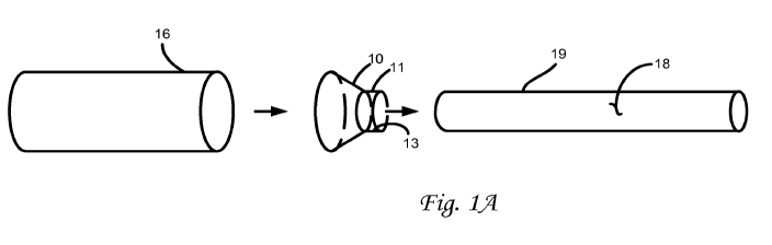
contexts known to those skilled in the art. Referring to Figure 1, extrusion
material (also
called feed stock, a blank or a billet) 16 is pressed through die 10 resulting
in an
extruded part 18. The die can be made by a number of manufacturing processes
including molding, forming and electric discharging machining.
[0047] Microstructures can be imparted to the surface of metal dies with
subtractive methods such as direct machining, cutting, or scoring, or laser
machining;
additive methods such as spraying, coating, or inserts incorporated onto the
die surface;
and surface alteration methods that neither add nor subtract such as micro
molding the
metal die surface.
[0048] Microstructures can be imparted to the surface of polymer dies
with
subtractive methods such as direct machining, cutting, or scoring, or laser
machining;
additive methods such as spraying, coating, or inserts incorporated onto the
die surface;
and surface alteration methods that neither add nor subtract such as micro
molding the
metal die surface. Polymer dies can also be molded, and microstructures can be
imparted via the mold. A common polymer die material is ultem. The
microstructured
molded polymer die can be machined after molding.
8
CA 02828499 2013-08-22
WO 2012/116301 PCT/US2012/026564
[0049] Microstructures can be imparted to the surface of ceramic dies with
subtractive methods such as direct machining, cutting, scoring, or laser
machining;
additive methods such as spraying, coating, or inserts incorporated onto the
die surface.
Ceramic dies can also be molded, and microstructures can be imparted via the
mold.
The microstructured molded ceramic die can be machined after micromolding.
[0050] Extrusion dies can be manufactured or have microstructures applied
to
them as indicated in the PCT application referenced above. Dies can include a
single
outlet opening or multiple outlet openings. Further, the die can be a single
part or an
assembly of parts. The die material can be metal, polymer or ceramic. Common
die
materials include steel, aluminum, and titanium.
[0051] Included in the die is an outlet die member 11 having an outlet
contact
surface 13 forming an outer surface of the resulting part. In one embodiment,
the
diameter of the blank is reduced though the extrusion process. As shown, die
10
contacts the blank on an outer surface 19 of the resulting part 18. In the
event that the
resulting part needs to include a cavity, a mandrel 12 can be included in the
die which
forms the cavity within the blank. Mandrel 12 can include a mandrel contact
surface 13
which forms an inner surface of the resulting part. Dies capable of forming
extruded
parts having cavities include spider dies, porthole dies or bridge dies.
[0052] Extrusion material can be metal or non-metal and can include rubber
(including natural rubber, styrene-butadiene, polybutadiene, neoprene,
ethylene-
propylene, butyl, nitrile, silicones), acrylic, nylon, polycarbonate,
polyester, polyethylene,
polypropylene, polystyrene, polyvinyl chloride, polyolefin and other flexible
polymers
known to those of skill in the art.
9
CA 02828499 2013-08-22
WO 2012/116301 PCT/US2012/026564
[0053]
Microstructures are included on the outlet contact surface. Microfeatures
can include holes, pillars, steps, ridges, curved regions, recessed regions,
raised
regions, and any combination of these employing any cross-sectional shape
including
circles, ellipses, triangles, squares, rectangles, polygons, stars, hexagons,
letters,
numbers, mathematical symbols and any combination of these.
[0054]
When the extrusion material comes in contact with microstructures on the
die, microstructures are imparted on the surface of the resulting part.
These
microstructures can increase hydrophobicity to the part, decrease
hydrophobicity to the
part and/or give the part a self-cleaning ability. The microfeatures can also
impart
optical effects, for example giving an object a prismatic effect, a specific
color, or a
directional dependent color change or color flop (e.g. the object appears a
specific color
when viewed from one angle and another color when viewed from another
direction).
[0055]
The microfeatures can also impart a surface friction or grip to the part, or
can give an object a specific tactile sensation such as feeling fuzzy, rough
or squishy
when touched. In a specific embodiment, the microfeatures can modify the heat
transfer characteristics of an object, for example by changing the surface
area of an
object, changing how the surface interacts with fluids, or changing the
behavior of
nucleation sites. In a specific embodiment, the microfeatures can result in a
decreased
heat transfer by conduction, for example when the microfeatures have a high
aspect
ratio only the tops of the microfeatures will be in contact with another
object for
conductive heat transfer while the voids between surface features will not
transfer heat
well. Further, the surface of the resulting part can include microstructures
that include
"drainage" abilities allowing fluids to drain from the part surface.
Further, the
CA 02828499 2013-08-22
WO 2012/116301 PCT/US2012/026564
microstructures can provide for a capillary action allowing fluid to flow
against gravity.
Friction can also be modified by particular microstructures imparted to the
surface of the
results part.
[0056]
Microstructures can also be electrically conductive, for example metal
microstructures or microstructures comprised of an electrically conductive
polymers.
These types of electrically conductive microstructures are useful, for
example, as an
array of electrical leads for electronic devices.
The electrically conductive
microstructures, for example, can be embossed directly onto the surface of an
object.
In some circumstances, the microstructures on the surface of the extrudate can
mirror
the microstructures on the die or mandrel. In other circumstances, the
microstructures
on the extrudate can be of a different size or shape. Extrudate drawing,
stretching, or
other manipulations can change the shape of the microstructures, for example,
shrinking the microstructures down in size by an order of magnitude or more.
[0057] In
a specific embodiment, the microfeatures have dimensions selected
over the range of 10 nm to 1000 pm. In an embodiment, for example, the
microfeatures
have a length, height, diameter, and/or width selected over the range of 10 nm
to 1000
pm, preferably for some embodiments selected over the range of 10 nm to 100
pm. In
an embodiment, for example, a pitch between microfeatures is selected over the
range
of 10 nm to 1000 pm, for some applications selected over the range of 1 pm to
1000
pm, and for some applications selected over the range of 10 pm to 1000 pm.
[0058] In
one embodiment, a preselected pattern of microfeatures includes a
region of microfeatures having a first cross sectional shape and a region of
microfeatures having a second cross sectional shape, for example different
from the
11
CA 02828499 2013-08-22
WO 2012/116301 PCT/US2012/026564
first cross sectional shape. In one embodiment, a preselected pattern of
microfeatures
includes a region of microfeatures having multiple cross sectional shapes
and/or sizes.
In an embodiment, a preselected pattern of microfeatures refers to two or more
arrays
of microfeatures of two or more cross-sectional shapes and/or sizes. In a
specific
embodiment, the two or more arrays are positioned side by side; that is, where
the two
arrays do not overlap. In another specific embodiment, the two or more arrays
are
positioned to overlap, and microfeatures having the two or more cross
sectional shapes
and/or sizes are interspersed within the overlapping arrays.
[0059] In an embodiment, a preselected pattern of microfeatures includes
multiple dimensions of microfeatures, for example a bimodal or multimodal
distribution
of dimensions. The size distribution could also be random, or the size could
correspond
to the location of the microfeature on the mandrel or die. In an exemplary
embodiment,
a preselected pattern of microfeatures includes a first group of microfeatures
having
dimensions selected from 10 nm to 1 pm and a second group of microfeatures
having
dimensions selected from 1 pm to 100 pm. In a specific embodiment, the sizes,
shapes
and positions of the microfeatures are preselected with micrometer-scale or
nanometer-
scale accuracy and/or precision.
[0060] In an embodiment, the microstructured surface comprises a polymer.
Useful polymers include, but are not limited to: PDMS, PMMA, PTFE, FEP, PEEK,
polyurethanes, Teflon, polyacrylates, polyarylates, thermoplastics,
thermoplastic
elastomers, fluoropolymers, biodegradable polymers, polycarbonates,
polyethylenes,
polyimides, polystyrenes, polyvinyls, polyoelefins, silicones, natural
rubbers, synthetic
rubbers and any combination of these.
12
CA 02828499 2013-08-22
WO 2012/116301 PCT/US2012/026564
[0061] In an embodiment, the microstructured surface comprises a metal.
Useful
metals include any moldable, castable, embossable and/or stampable metal or
alloy.
Useful metals include, but are not limited to: aluminum, aluminum alloys,
bismuth,
bismuth alloys, tin, tin alloys, lead, lead alloys, titanium, titanium alloys,
iron, iron alloys,
steel, stainless steel, hastelloy, inconel, duranickel, indium, indium alloys,
gold, gold
alloys, silver, silver alloys, copper, copper alloys, brass, nickel, nickel
alloys, platinum,
platinum alloys, palladium, palladium alloys, zinc, zinc alloys, cadmium and
cadmium
alloys.
[0062] In one embodiment, the extrusion material 16 can be drawn over an
inner
die 14. The outer surface of the internal die can have microstructures which
cause
microstructures to be imparted on the inner surface of the extrusion material.
In one
embodiment, the extrusion material is a tube with a central cavity.
[0063] The extrusion material can be drawn in a manner which will reduce
its
diameter or its thickness or both after the extrusion material leaves contact
with the die.
In one embodiment, the extrusion material, having a cavity, can be drawn
through
drawings die 15 which will reduce the diameter of the out perimeter, the bore
of the
extrusion material or both.
[0064] In embodiments, one or more physical, mechanical or optical
properties,
other than and/or in addition to hydrophobicity, are established, varied
and/or controlled
by deforming a flexible substrate having a plurality of microfeatures disposed
thereon.
In an embodiment, for example, an optical property, such as the reflectivity,
wavelength
= distribution of reflected or scattered light, transparency, wavelength
distribution of
transmitted light, refractive index or any combination of these, is controlled
by flexing,
13
CA 02828499 2013-08-22
WO 2012/116301 PCT/US2012/026564
bending, expanding, stretching and/or contracting the flexible substrate
having a
plurality of microfeatures disposed thereon. In an embodiment, a physical
property,
such as aerodynamic resistance or hydrodynamic resistance is controlled by
flexing,
bending, expanding, stretching and/or contracting the flexible substrate
having a
plurality of microfeatures disposed thereon. In an embodiment, a tactile
property of the
surface, such as the surface's tactile sensation, is controlled by flexing,
bending,
expanding, stretching and/or contracting the flexible substrate having a
plurality of
microfeatures disposed thereon.
[0065] Figure 2 illustrates that microstructures can be imparted on a
resulting part
without necessarily changing the dimension of the resulting part from that of
the
extrusion material. Therefore, the negative microstructures on the die are
imparted to
the resulting part in generally a 1:1 ratio. When the resulting part
dimensions are
modified through the extrusion process, the ratio of size between the
extrusion material
and the resulting part can be up to 7:1 and greater. In one embodiment, shape
of the
resulting part produced from the die or mandrel can be preserved during the
drawing, or
the shape can change. The shape preservation or shape change can depend upon
the
properties of the extrusion material or how the extrusion material is
subsequently
processed.
[0066] When the diameter size of the extrusion material is changed after
the
microstructures are imparted on the resulting part, the microstructures on the
part are
changed. Therefore, the microstructures contained on the die are larger than
that of the
resulting microstructures on the resulting part to account for the shrinking
of the
resulting part from the extrusion material.
14
CA 02828499 2013-08-22
WO 2012/116301 PCT/US2012/026564
[0067] When the dimensions of the resulting part change from the extrusion
material, one embodiment has the resulting contact angle of the
microstructures on the
die including in the range of 100 degrees to 120 degrees while the
microstructures of
the resulting part are between 101 degrees and 170 degrees. When the
dimensions of
the resulting part change is from the extrusion material, one embodiment has
the
resulting friction properties of the resulting part being 20 times less than
the friction
properties of the microstructures on the die. One embodiment has the resulting
friction
properties of the resulting part being 100 times more that the friction
properties of the
microstructure on the die. When the dimensions of the resulting part change
from the
extrusion material, one embodiment has the microstructures on the die on a
scale of
mm or pm while the microstructures on the resulting part will generally be in
the scale of
pm or nm.
[0068] Referring to Figure 3, the location of microstructures on the die
can vary
with the preferred embodiment placing the microstructures at location 26a as
shown.
Referring to Figure 4, blank 16 can also be extruded with only a portion of
the die
having a negative of a microstructure shown as 28. When the extrusion material
is
forced across the die, the shape created by the interaction with the die
imparts on the
resulting part and can include microstructures. The blank can be manufactured
into a
resulting part through extrusion including drawing the blank through the die.
[0069] Referring to Figure 5, outer surface of a resulting part is shown
as 30
having a space 32 between the microstructures. When the extrusion material is
drawn
down the microstructures on the outer surface are modified, the
microstructures
themselves and the space between the microstructures is compressed as shown in
CA 02828499 2013-08-22
WO 2012/116301 PCT/US2012/026564
drawn down resulting part 34. The same effect is realized with microstructures
that are
on the inner surface of the extrusion material as shown in extrusion inner
surface 36
and drawn down extrusion inner surface 38.
[0070] Referring to Figure 6, the extrusion process is shown in further
detail.
Feed stock 40 is placed in hopper 42. The feed stock is then mixed and melted
in
extrusion chamber 44. The heated feed stock is pumped or otherwise drawn out
of the
extrusion chamber through a pump or gears 46 and forced through a dye, mandrel
or
both shown as 48. The extrudate produced by the dye or mandrel, having
microstructures, can then be cooled by a cooling assembly 50 such as an air
blower or
quench bath, cut by cutter 52 or rolled on a spool 54. In the event that the
spool rotates
at a faster speed then the extrudate exits the die, the extrudate can be drawn
to a
smaller cross-section dimension.
[0071] It should be noted that there can be a plurality of quench baths
using
various quenching solutions. For example, when extruding aluminum, a quench
bath of
salt followed by a quench bath of water can be used. The temperature of the
quench
baths, the time between the extrudate exiting the dye and entering the quench
bath and
the length of time the extrudate is in the quench bath can vary.
[0072] In one embodiment, a puller 54 having an upper belt drive 56 and a
lower
belt drive 58 pulls the extrudate from the dye and into the cutter or toward
the spool.
With a puller, the extrudate can be drawn when the pull of the puller is
greater than the
extrusion rate of the extrudate from the dye. This results in the extrudate
being
stretched resulting in a smaller diameter extrudate. Additionally, the
extrudate can also
shrink when the extrudate is quenched and when the extrudate is rolled onto a
spool.
16
CA 02828499 2013-08-22
WO 2012/116301 PCT/US2012/026564
[0073] Referring to Figure 7, a portion of one microstructure of a
circular die is
shown. The die 60 includes a plurality of microfeatures 62 each having a first
wall 64
and a second wall 66. A channel 68 is defined in the die having a width 70. A
first arc
72 can be included in a lower surface 74. A second arc 76 can also be included
in the
lower surface overlapping the first arc. In use, the die can produce an
extrudate 78
having microstructures 80. It should be noted that the extrudate
microstructure is not a
mirror image of the die microstructures as the extrudate microstructures have
physical
dimensions as the extrudate cools, is drawn or otherwise physically altered
after the
leaving the extrusion die. In one embodiment, the radius of the first arc is
in the range
of 45 to 65 pm. The channel width is in the range of 150 to 250 pm and the
height 80 is
in the range of 250 to 350 pm. The resulting extrudate microstructures can be
between
7 and 13 pm in width and height can have generally a sloped peak
configuration.
[0074] Referring to Figure 8, another microstructure is shown. A lower
surface
82 and a upper surface 84 are included in the die. A first wall 86 and second
wall 88
can be included in the microstructure. A channel 90 can be defined in the
microstructure having a width 92 and a height 94. An arc 94 can be defined in
the
lower surface. A second channel or arc 96 can be defined in the upper surface.
In one
embodiment, the channel height is in the range of 0.8 to 1.6 mm and the height
is in the
range of 1.0 to 2.0 mm. The resulting microstructures 98 on the extrudate can
have a
height in the range of 70 to 90 pm, a width in the range of 120 to 160 pm and
can also
have a general slope shape.
[0075] Referring to Figure 9, another microstructure is shown. A first
wall 100 is
shown having an angle of incident EY in relation to the upper surface less
than 90 and
17
CA 02828499 2013-08-22
WO 2012/116301 PCT/US2012/026564
=
an angle of incident 0" in relation to the upper surface greater than 900. A
first arc 102
can be included in the lower surface and a second arc 104 can be included in
the lower
surface adjacent to the first arc. A channel 106 defined in said die can have
a width 106
that in one embodiment is in the range of 0.25 to 1.25 mm and a height in the
range of
0.25 to 1.25 mm. This arrangement of the first wall, first arc, second arc and
second
wall is a overhang microstructure.
During the extrusion process, the extrudate
microstructure can shrink through drawings, cooling or other reason resulting
in a
extrudate microstructure that is generally smaller than the original mirror of
the die
microstructure. The height of the resulting extrudate microstructure 110 can
be in the
range of 20 to 60 pm and have a width of between 100 and 140 pm. A upper arc
108
can be included in the upper surface.
[0076] In
one embodiment, the sides of the resulting extrudate microstructure are
generally vertical. In another embodiment, the walls can be slanted as shown
in Figure
10. The slanted walls can result from a nylon extrudate manufactured with a
line speed
of 200 feet per second, drawn down about 3.2 times and cooled with a water
quench
bath. The width 112 of the extrudate can be in the range of 250 to 250 pm and
the
height can be in the range of 150 to 250 pm. A channel 114 can be included in
the
upper surface of the die and can have three sides of a generally trapezoidal
shape. The
resulting extrudate microstructure could be a generally round microfeature
included on
the extrudate. The microstructure can have a width in the range of 1000 to
1400 pm
and a height in the range of 500 to 1000 pm. The resulting extrudate can have
a height
in the range of 90 to 210 pm and a width in the range of 100 to 380 pm. -
18
CA 02828499 2013-08-22
WO 2012/116301 PCT/US2012/026564
[0077] Referring to Figure 11, a channel 120 can have a first wall 122, a
second
wall 124 and a arc 126 disposed at the lower surface and between the first and
second
wall. The channel can have a width in the range of 100 to 140 pm and a height
in the
range of 200 to 360 pm. The resulting extrudate microstructure 128 can have a
height
between 45 to 60 pm and a width of 40 to 50 pm.
[0078] Referring to Figures 12 and 13, an extrusion die 130 includes an
opening
132 having microstructures. As shown, the die is a flat die that can include
one or more
parts. Microstructures 134 are disposed along the interior surface of the die.
In one
embodiment, a first wall 136 has an angle of incident 8' that is less than 90
, a first arc
138 adjacent to the first wall, a planar portion 140, a second arc 142 and a
second wall
144 having an angle of incident 8" greater than 90 . The resulting extrudate,
shown in
Figure 14, is a film or otherwise flat extrudate having microstructures 146
which are
generally in the range of 200 to 240 pm apart with a height in the range of 30
to 40 pm.
[0079] Referring to Figure 15A, a circular die 150 is shown having
microstructures 152 disposed along an inner surface of the die. Referring to
Figure
15B, one embodiment of the microstructure is shown. Opening 154 is defined in
the die
with microstructure 156 surrounding the opening. The microstructures define a
first arc
158 and a second arc 160 in an alternating pattern wherein the depth of the
first arc is
greater than the depth of the second arc.
[0080] Referring to Figure 16A, another microstructure for a circular die
is shown.
The microstructure includes a first wall 162 having an angle of incident 8' in
relation to
the upper surface of less than 90 and a second wall 164 having an angle of
incident 8"
in relation to the upper surface of greater than 90 . A first arc 166 can be
included in
19
CA 02828499 2013-08-22
WO 2012/116301 PCT/US2012/026564
said microstructure adjacent to a second arc 168. A lower planar surface 170
can in
included in the microstructure and disposed between the first and second arc.
An upper
cavity 172 can be included in said upper surface and can be arranged in an
alternating
pattern in said microstructure.
[0081] Referring to Figure 17, another microstructure for a circular die
is shown
having a first wall 174 and a second wall 176 defining a cavity 180 having a
lower
planar surface 178. In one embodiment, the first and second wall have a height
in the
range of 400 to 480 pm and a width in the range of 360 to 380 pm. Figure 18
shows a
upper arc 182 defined in the upper surface. In one embodiment, the upper arc
has a
width in the range of 100 to 160 pm and a depth in the range of 100 to 160 pm.
Figure
19 shows a lower arc 184 defined in the lower surface.
[0082] Referring to Figure 20, another microstructure is shown having a
first wall
and a second wall defining a cavity. A first arc 186 is defined in the lower
surface and in
the cavity. A pair of arcs 188a and 188b are defined in the walls of the
cavity.
[0083] Figure 21 shows a mandrel 190 having microstructures 200 so that an
extrudate made using the mandrel would have microstructures formed on the
inner
surface of the extrudate. Figure 22 shows that the microstructures of the
mandrel have
a height 202.
[0084] Figure 22A shows an extrudate 210 manufactured with a mandrel that
does not include microstructures. The inner surface 212 is smooth resulting
from a
mandrel that does not include microstructures. Figure 22B, however, shows an
extrudate 214 having microstructures 216 that are formed on the inner surface
218 by a
mandrel which includes microstructures. Figure 22C shows a mandrel 220 in one
CA 02828499 2013-08-22
WO 2012/116301 PCT/US2012/026564
embodiment having a first circular portion 222 and a second circular portion
224 that are
adjacent to each other. Microstructures 226 are located at the junction 228
between the
circular portions. Smooth portion 230a and 230b are located on the respective
circular
porions as shown in Figure 22D.
[0085] The terms and expressions which have been employed are used as
terms
of description and not of limitation, and there is no intention in the use of
such terms and
expressions of excluding any equivalents of the features shown and described
or
portions thereof, but it is recognized that various modifications are possible
within the
scope of the invention claimed. Thus, it should be understood that although
the present
invention has been specifically disclosed by preferred embodiments and
optional
features, modification and variation of the concepts herein disclosed may be
resorted to
by those skilled in the art, and that such modifications and variations are
considered to
be within the scope of this invention as defined by the appended claims.
21