Note: Descriptions are shown in the official language in which they were submitted.
CA 02828680 2015-09-28
SYSTEM AND APPARATUS FOR ITEM MANAGEMENT
CROSS REFERENCE TO RELATED APPLICATION
This application is a division of Canadian Patent Application Serial No.
2,628,789, filed April 10, 2008.
FIELD
The field relates generally to item management and, more particularly, to item
management providing for improved efficiency in item distribution.
BACKGROUND
Personnel involved in handling of items are routinely required to manage and
organize the items for delivery to an appropriate user or process. An item as
used
herein, means or refers to a separate article, object, or product. Care is
required to ensure
that the correct item is delivered to the user or process. Examples of such
item-
management tasks involve handling of medicament or nutriceutical items
ultimately
intended for use by a patient, consumer, or other user. A medicament means or
refers to
a medication product while a nutriceutical can represent a dietary supplement
which
provides health or medical benefits. (e.g., a vitamin, a mineral, or a
supplement.)
Items such as medicaments and nutriceuticals are provided in various physical
forms, such as solid or substantially solid forms, granular forms, gel forms,
and liquid
forms. Solid or substantially solid medicament and nutriceutical items may be
shaped
into small solid tablets in the physical form of capsules, spheres, ovals,
disks, multi-
angles, squares, triangles, and ellipses. Gel, granular, or liquid-form items
may be
packaged in the form of small capsules and gel caps (for oral consumption), or
ampules
containing a liquid. Medicament and nutriceutical items may also be provided
which
differ in strength of the active chemical constituent. For example, a single
medicament
or nutriceutical item may be provided with a concentration of 1, 5, or 10
milligrams of
the active chemical constituent.
One way in which the foregoing types of items are managed for delivery to the
ultimate user is through automated dispensing machines. Automated dispensing
-1-
,
CA 02828680 2013-09-27
machines are frequently utilized by pharmacies, hospitals, long-term care
facilities, and
others in the health-care field for purposes of automatically dispensing
medicaments
required to fulfill patient prescription orders and to dispense medicaments
administered to
patients in hospitals and long-term care facilities, such as nursing homes.
Automated
dispensing machines can also be used in retail distribution, such as to
dispense
nutriceutical or food items. Such automated dispensing machines are computer
controlled
to dispense an appropriate quantity of medicaments and, typically, to package
the
medicaments. And, automated dispensing machines can typically be programmed to
dispense and package all medicaments required to fulfill all prescription
orders and
dispense requests for a given eight-hour work shift. The automated dispensing
machine
will proceed to automatically execute the instructions until all requested
medicaments
have been output.
Automated dispensing machines typically store and dispense a plurality of
different medicament types. Medicaments which are frequently prescribed or
utilized,
referred to as "fast-moving" medicaments, are stored within the automated
dispensing
machines in large quantities as loose, bulk form items within cassettes,
cells, canisters,
magazines, racks, or other storage apparatus. A single medicament type is
stored in each
storage apparatus.
Medicaments which are less frequently prescribed or utilized are referred to
as
"slow-moving" medicaments. Medicament types which are infrequently required
may be
stored in the automated dispensing machine in what is referred to as an
"exception storage
apparatus," a type of storage apparatus which derives its name merely from
being an
alternative to the medicament storage apparatus used for the faster moving
medicaments.
Slow-moving medicaments could include medicament types with unusual chemical
constituents or with unusual active-constituent concentrations. An exception
storage
apparatus stores small quantities of the less-frequently used medicaments
which could
not be efficiently stored in large bulk quantities. Unlike the cassettes,
cells, canisters,
magazines, racks, or other storage apparatus for the faster moving
medicaments, more
than one medicament type can be stored in a single exception storage
apparatus.
An exception storage apparatus can be provided, for example, as a drawer, or
as a tray-like device, which pulls out from the automated dispensing machine
and
which includes a plurality of medicament-holding cells, or compartments, for
holding
-2-
CA 02828680 2013-09-27
one medicament item or a small quantity of medicaments. In certain automated
dispensing machine types, the cells of the exception storage apparatus are
movable
along a track. The cells can be indexed forward along the track toward an
opening so
that the cell contents fall serially (i.e., one-after-the-other) through a
cell bottom
opening for packaging by the machine. Any number of cells can be provided in
the
exception storage apparatus. For example, an exception storage apparatus could
include 64 total cells grouped in four rows of 16 cells all movable along the
track.
More than one exception storage apparatus may be provided.
The exception storage apparatus offers the operator an opportunity to increase
the range of dispensing options because more than one type of medicament can
be
stored in such storage apparatus. For example, the medicaments can be arranged
in
the exception storage apparatus to dispense medicaments for a particular
patient
according to the order in which the medicaments are to be taken by the patient
(e.g.,
breakfast, lunch, and dinner) or can be loaded to meet the medicament
requirements
of more than one patient.
Upon activation, the automated dispensing machine automatically meters out
from the appropriate storage apparatus the desired quantity of medicament(s)
called
for by the prescription order or dispense request. The medicament item or
items are
directed from the storage apparatus to the packaging apparatus by means of
gravity
through a chute or other guide apparatus, or by mechanical means such as an
auger.
The packaging device may then load the dispensed medicaments into one or more
packages. The type of package utilized is based on the capability of the
particular
type of automated dispensing machine. By way of example only, automated
dispensing machines may load the medicaments into containers such as vials,
bottles,
blister packages, or pouch packages. The medicament or medicaments, once
packaged in the container type utilized by the automated dispensing machine,
may
then be delivered to the patient or other designated user.
Loading or replenishment of the cassettes, cells, canisters, or other storage
apparatus for the fast moving medicaments is relatively easy. All that is
required is
placement of a loaded storage apparatus into the machine (e.g., in place of a
depleted
storage apparatus) or the pouring of a quantity of the bulk-form medicaments
into a
-3-
CA 02828680 2013-09-27
depleted storage apparatus. However, loading or replenishment of the cells or
compartments of the exception storage apparatus is more problematic because a
human
being must manually load or replenish the cells or compartments. In a
pharmacy,
hospital, or long-term care facility, the human is a pharmacy technician or a
registered
pharmacist. The technician or pharmacist must manually load the medicament
items
directly into the exception storage apparatus cells. Altematively, the
medicament
items can be placed into the cells of a "loading device." A loading device is
a device
with cells or compartments that correspond to the cells of the exception
storage
apparatus. The loading device can be loaded at a workstation and carried to
the
automated dispensing machine so that the medicament contents of the loading
device
can be transferred into the appropriate cells of the exception storage device.
By way
of example only, a busy pharmacy might use dozens of different loading devices
to
load the exception storage apparatus during a given work shift.
The exception storage apparatus loading process is tedious and time
consuming, irrespective of whether the medicament items are placed directly
into the
exception storage apparatus cells or are placed into the cells of a loading
device for
transfer to the exception storage apparatus. As can be appreciated, the
loading
process must be undertaken in a deliberate and considered manner to ensure
that the
correct medicament is placed in the correct cell or compartment. Placement of
the
correct medicament in the correct cell or compartment can be difficult because
the
cells or compartments of a typical exception storage apparatus or loading
device are
relatively small and are in close proximity to each other. The chance of an
inadvertent error may be increased because certain medicaments have similar
shapes,
sizes, and appearances.
Typically, printed paper instructions are generated which direct the
technician
or pharmacist to place the required medicament into a designated cell or
compartment. At a minimum, valuable time is required to follow the
instructions. The
instructions may require complex ordering of different medicament types among
the
cells raising the possibility, no mater how slight, that the wrong medicament
could be
placed in a cell or compartment. And, because the technician or pharmacist
must take
her eyes off the exception storage apparatus or loading device to read the
instructions,
-.4-
CA 02828680 2013-09-27
and because the cells typically look alike, there is also a slight possibility
that the
wrong medicament item could be placed in the cell. And, since more than one
loading device could be used by a pharmacy, there is a possibility, no matter
how
remote, that an incorrect loading device could be used to load the exception
storage
apparatus.
If a pharmacist is required to inspect a loading device or exception storage
apparatus before use to verify that the medicaments were loaded correctly,
then the
pharmacist must essentially repeat the loading process to confirm that the
correct
medicament was received in the correct cell.
A skilled pharmacist's time is extremely valuable. Time spent loading an
exception storage apparatus is time that could be spent counseling patients.
And, an
automated dispensing machine must typically be deactivated or taken "off line"
in
order to load the exception storage apparatus. Any time spent loading an
exception
storage apparatus can represent lost productive time in which the automated
dispensing machine cannot be used to fulfill prescription orders or dispense
requests,
thereby decreasing efficiency and increasing costs to the operator.
Problems similar to those described for operators of automated medicament
dispensing machines can exist for operators of other types of automated
dispensing
machines in which both fast and slow moving items must be dispensed from a
single
machine. For instance, the same issues would face the operator of an automated
dispensing machine used to dispense nutriceutical products or other retail
food
products.
There is a need for an item-management system, apparatus and methods which
would improve the item management and distribution process, which would
facilitate
more accurate item management and distribution, and which would reduce the
time
needed to manage items, thereby freeing personnel for other important tasks
and
improving the quality of care which can be offered.
SUMMARY
Item-management systems, apparatus and methods are described. The
systems, apparatus, and methods facilitate management and organization of
items,
-5-
CA 02828680 2013-09-27
=
such as medicaments. The systems, apparatus, and methods may be used, for
example, to ensure that the correct item is provided to a user or other
process. The
systems, apparatus, and methods are described in the preferred context of
management of
medicament-type items but can have application with respect to management of
other
items, such as nutriceuticals.
In embodiments, an item-management system comprises a holder having
plural cells, a docking station to which the holder is docked, at least one
indicator
selectively-operable to indicate the cell of a docked holder into which an
item is to be
received, and at least one controller operable to selectively operate each at
least one
indicator to indicate the cell into which the item is to be received.
In embodiments, a holder for management of items comprises a body defining
plural cells. Preferably, each cell has an inlet and an outlet. It is further
preferred that
at least one gate is mounted with respect to the body and each cell outlet.
The
preferred gate is movable between a first position in which the cell outlet is
closed to
receive an item in the cell and a second position in which the cell outlet is
open to
discharge the item from the cell. A preferred gate type is a shuttle member.
Preferably, the shuttle member includes a pull permitting user operation of
the shuttle
member. In embodiments, the holder cells are in alignment with corresponding
cells
of an automated dispensing machine exception storage apparatus, thereby
permitting
rapid transfer of medicaments from the holder cells, preferably through the
outlets,
and to the automated dispensing machine.
At least one indicator proximate each cell is selectively operable to indicate
the cell into which an item is to be received. The indicators can also be used
for
verification that the correct item was placed into the cell. Each at least one
indicator
provides visible information to the technician, pharmacist or other user,
freeing
personnel from reliance on written instructions regarding the medicament or
other
item to be placed in each holder cell. In embodiments, each at least one
indicator is a
lamp. Preferably, each lamp is a light-emitting diode, also known as an LED.
In
embodiments, a plural-lamp indicator consisting of more than one indicator can
be
provided proximate each cell, for example to provide different types of
information.
For example, each indicator may indicate the quantity or type of medicament to
be
-6-
CA 02828680 2013-09-27
placed in each cell. Plural indicators with colors that differ, or a single
multi-colored
indicator, lamp, or LED may be used, also to communicate useful information to
the
user.
In preferred embodiments, the indicators are associated with the holder. In
other preferred embodiments, the indicators may be associated with a guide
provided
as part of the docking station. The preferred guide is located above a holder
docked at
the docking station and includes openings in registry with the holder cells.
The
indicators indicate which opening through which to place the medicament or
other
item to load the medicament or item into the appropriate holder cell.
In embodiments, a holder may be docked to a docking station by an electro-
mechanical connection between mating contacts on the holder and docking
station
when a holder is docked. In other embodiments a holder may be docked to a
docking
station by a wireless connection with, or without, direct physical contact
between the
holder and docking station. Each connection type enables the selective
indicator
operation. A preferred holder body may include structure facilitating
alignment of the
holder and docking station for holder docking. In yet other embodiments, a
holder
may be directly connected to a controller, without a docking station.
Preferred
docking station embodiments may include a video display operably connected to
the
at least one controller and an input device (e.g., a keyboard and/or mouse)
enabling a
user to input information to the at least one controller. Preferably, the
video display is
operable to display information which indicates the cell into which each
medicament
is to be received.
Preferably, the at least one controller is operatively connected to each at
least
one indicator when the holder is docked at the docking station. It is
preferred that the
at least one controller comprises a computer including a set of instructions
operable to
selectively operate each at least one indicator. Most preferably, the at least
one
controller further includes a programmable logic controller operatively
connected to
the computer and the PLC selectively operates each at least one indicator. In
embodiments, the instructions may be operable to selectively operate the
indicators to
control loading of a medicament into a cell for a patient or for a plurality
of patients.
The instructions may be operable to store information about the medicament
loaded
-7-
CA 02828680 2013-09-27
,
,
into each cell.
Methods for management of medicaments and items are shown and described
herein.
BRIEF DESCRIPTION OF THE DRAWINGS
Exemplary item-management systems, apparatus, and methods may be
understood by reference to the following description taken in conjunction with
the
accompanying drawings, in which like reference numerals identify like elements
throughout the different views. For convenience and brevity, like reference
numbers
are used for like parts amongst the embodiments. The drawings are not
necessarily to
scale, emphasis instead being placed upon illustrating the principles of the
invention.
In the accompanying drawings:
FIGURE 1 is a perspective view of a representative holder docked at a
docking station;
FIGURE 2 is a schematic side sectional view of the representative holder and
docking station taken along section 2-2 of Figure 1;
FIGURE 3 is a schematic top sectional view of a representative holder docked
at a docking station taken along section 3-3 of Figure 1 with certain holder
portions
cut away to facilitate understanding;
FIGURE 4 is a top side view of the representative holder of Figure 1;
FIGURE 5 is a left side elevation view of the representative holder of
Figure 1;
FIGURE 6 is a schematic top sectional view of a representative wireless-type
holder docked at a docking station taken along a section, such as section 3-3
of Figure
1 with certain holder portions cut away to facilitate understanding;
FIGURE 7 is a perspective view of a further exemplary embodiment showing
a docking station with a guide, and a holder docked at a docking station;
FIGURE 8 is a schematic side sectional view of the further exemplary docking
station and guide taken along section 8-8 of Figure 7;
FIGURE 9 is a schematic top sectional view of the further exemplary docking
station and guide taken along section 9-9 of Figure 7;
-8-
CA 02828680 2013-09-27
FIGURE 10 is a top side view of the holder shown in Figures 7-9 shown apart
from the docking station;
FIGURES 11A-11C are enlarged fragmentary views of region 11 of Figures 3,
6, and 9 provided to illustrate an alternative indicator embodiment comprising
a
multi- colored lamp which may be used with the holders or guide of Figures 3,
6, and
9;
FIGURE 11D is an enlarged fragmentary view of region 11 of Figures 3, 6,
and 9 provided to illustrate a further alternative indicator embodiment
comprising a
tri-lamp indicator which may be used with the holders or guide of Figures 3,
6, and 9;
FIGURE 12A is a schematic illustration of an exemplary system including a
docking station and computer external to the docking station;
FIGURE 12B is a schematic illustration of a further exemplary system
including a docking station and computer internal to the docking station;
FIGURE 13 is a perspective view of a storage cabinet including four
representative holders temporarily stored therein;
FIGURE 14 is an exemplary log-on screen display;
FIGURE 15 is an exemplary screen display for loading of a holder;
FIGURE 16 is an exemplary screen display for verification of the items loaded
in the holder;
FIGURE 17 is an exemplary screen display for verification of the items loaded
in the holder including a reference image of a medicament;
FIGURE 18 is a perspective view of an exemplary automated medicament
dispensing machine with which the representative holders of Figures 1-10 may
be
utilized;
FIGURE 19 is a perspective view of the exemplary automated medicament
dispensing machine of Figure 18, but with one exemplary exception storage
apparatus
in an outwardly-extended position ready to receive medicaments;
FIGURE 19A is an enlarged fragmentary view of a portion of the exemplary
exception storage apparatus of Figure 19;
FIGURE 20 is a perspective view of the exemplary automated medicament
dispensing machine of Figures 18 and 19 but with the representative holder of
-9-
CA 02828680 2016-08-03
Figures 1-10 positioned on the exemplary exception storage apparatus:
FIGURES 21A-21C are schematic side sectional views of the representative
holder of Figures 1-5 and exception storage apparatus of Figures 19-20 taken
along
section 21-21 of Figure 20. Figures 21A-21C show an exemplary sequence for
loading the contcnts of the holder into the exception tray; and
FIGURE 22 is an exemplary series of medicament-containing pouch packages
of the type produced by the automated dispensing machine of Figures 18-20.
While the systems, apparatus, and methods are susceptible to various
modifications and alternative forms, specific embodiments thereof have been
shown
by way of example in the drawings and are herein described in detail. It
should be
understood, however, that the description herein of specific embodiments and
rnethods is not intended to limit the invention to the particular forms
disclosed, but on
the contrary, the intention is to cover all modifications, equivalents, and
alternatives
falling within the scope of the invention as defined by the appended claims.
DETAILED DESCRIPTION
Referring first to Figures 1-9 and 12A, there are shown embodiments of an
exemplary system 10 for management of items. The embodiments are described in
the context of a preferred item-management system for management of medicament
11 items. System 10, preferably includes holder 13, docking station 15 to
which
holder 10 may be temporarily docked, and controller 17 which may include one
or
more controls capable of operating system 10. The term "at least one
controller,"
therefore, means or refers to embodiments in which controller 17 includes one
or
more controller components. Controller 17 may include components internal
and/or
external to docking station 15. In a further exemplary system 10' (Figure
12B),
controller 17 is illustrated as being entirely within docking station 15.
System 10 may
be configured and arranged based on the needs of the pharmacy, hospital, long-
temi
care facility or other operator. While it is envisioned that embodiments of
system 10
or 10' will be utilized in the health-care industry, it should be understood
that such
systems and others may have application in fields outside of the health-care
industry
for dispensing of items other than medicaments 11.
-10-
CA 02828680 2013-09-27
Referring then to Figures 1-5, there is shown an exemplary holder 13 for
managing and organizing medicaments. A further exemplary holder 13' is
illustrated
in Figure 6. The word "holder" means or refers to apparatus which holds one or
more
items. Holder 13' is a wireless-type holder but is otherwise identical to
holder 13. For
simplicity and brevity, like reference numbers of holder 13 and docking
station 15 are
used to identify like parts of holder 13' and docking station 15' and the
description of
holder 13 and docking station 15 are incorporated by reference with respect to
holder
13' and docking station 15'.
Exemplary holder 13, 13' has a tray-like appearance in that holder 13, 13' is
a
flat, shallow container used for carrying, holding, and organizing items which
are
preferably medicaments 11. However, other holder configurations may be
utilized
depending on the needs of the user.
Exemplary holder 13, 13' includes a body 19, a top and a bottom 21, 23, a
front and a rear side 25, 27, and a left and a right side 29, 31. Holder 13,
13' further
includes cells, of which cell 33 is representative. Each cell 33 is defined by
a wall 35,
of which wall 35 is representative. For purposes of simplicity and brevity,
each cell
33 of holder 13, 13' is indicated by reference number 33 and each wall is
indicated by
reference number 35.
Each wall 35 defines a cell 33 upper opening, or inlet 37, and a cell lower
opening, or outlet 39. As shown in the examples, the cell inlets 37 extend
through,
and are included in and along, the body top 21 while the cell outlets 39
extend
through, and are included in and along, the body bottom 23. In the
embodiments,
medicaments 11 are loaded into each cell 33 through inlet 37 and are
discharged from
cell 33 through outlet 39 as described in detail below.
In the embodiments, each cell 33 is identical and, as noted, reference number
33 indicates each identical cell 33. However, it is possible that cells 33 of
holder 13,
13' may have a structure which is not identical and which may differ depending
on the
needs of the user.
Referring to Figures 1-6 each exemplary holder 13, 13' shown includes sixty
four total cells 33 organized into four rows of sixteen cells. In the
examples, the
organization of cells 33 is identical to the organization of cells 41 of
exception storage
-11-
CA 02828680 2013-09-27
apparatus 43 shown pulled out from automated dispensing machine 45 in Figures
18-
21C. Exemplary holder 13, 13' is configured and arranged such that each cell
33
outlet 39 is in registry with (i.e., aligned with) a corresponding cell 41 of
exception
storage apparatus 43 permitting direct movement of medicaments 11 from holder
13,
13' into exception storage apparatus 43 as shown in the example of Figures 21A-
21C.
Holder top 21 is preferably provided with human-readable indicia 47
identifying each cell 33. In the examples, indicia 47 is an integer from 1 to
64
proximate each cell 33. Other types of indicia 47 may be used, such as alpha-
numeric
indicia.
Holder 13, 13' further includes at least one indicator 49 for each cell 33, of
which indicator 49 is representative. For purposes of simplicity and brevity,
each
indicator of holder 13, 13' is indicated by reference number 49. An indicator
49 is
located on holder 13, 13' top side 21 next to each cell 33. Each indicator 49
could be
located inside body 19 if body is translucent. One indicator 49 is provided
for each
cell 33 for a total of sixty four indicators 49 in these examples. Each
indicator 49 may
be a visible indicator in the form of a selectively-operable lamp (i.e., an
artificial light
source). Energizing of each lamp-type indicator 49 indicates the cell 33 into
which
the medicament 11 or other item is to be loaded. Preferably, each indicator 49
is a
light-emitting diode (LED), although it is envisioned that other types of lamp-
type
indicators 49 may be used.
Controller 17 is operable to selectively operate each indicator 49 when holder
13 is docked at docking station 15. Selective operation of an indicator 49
proximate
to a cell 33 prompts the technician or pharmacist to place each medicament 11
into
the cell 33 associated with the activated indicator 49 or indicators 49.
Collectively,
the indicators 49 comprise a type of pick-to-light system. Thus, if a
medicament 11 is
to be loaded in the cells 33 designated by human-readable indicia 47 as cells
1, 3, 6, 9,
12, 15, 18, 21, 24, and 27, each of the indicators 49 next to such cells 33
may be
activated communicating to the technician or pharmacist the specific cells 33
which
should contain that medicament 11. Use of a pick-to-light system of indicators
49
advantageously communicates information to the technician or pharmacist
without
resort to a set of written instructions. A pick-to-light system is far
superior to written
-12-
CA 02828680 2013-09-27
=
instructions because the person responsible for loading or verification of
holder 13,
13' need not take his or her eyes off of holder 13, 13' to read the
instructions thereby
increasing accuracy and reducing the time required to load or verify the
medicaments
11 that should be in the holder 13, 13'.
As illustrated in yet a further embodiment illustrated in Figures 11A, 11B,
and
11C, indicator 49 could comprise a single multi-colored indicator 49 for each
cell 33.
For example a multi-colored LED lamp could be used as indicator 49. As is
known,
changing the voltage to a multi-colored LED or selectively activating one of
plural
LED anodes causes the LED to emit a different color as represented in Figures
11A-
11C. Each different color can be used to communicate a different type of
information
to the technician loading the holder 13, 13'. For example, a red color signal
from
indicator 49 (Figure 11A) could indicate that one medicament 11 is to be
loaded into
that cell 33. A green-color signal from indicator 49 (Figure 11B) could
indicate that
more than one medicament 11 is to be loaded in that cell 33. A yellow-color
signal
from indicator 49 (Figure 11C) could indicate that a half-size medicament is
to be
loaded in that cell 33.
A further indicator 49 embodiment is illustrated in Figure 11D. In the
example of Figure 11D, a plural-lamp indicator 49 could be provided for each
cell 33
for purposes of communicating information to the technician or pharmacist. In
Figure
11D, a plural-lamp indicator 49 consisting of three lamps is provided adjacent
each
cell 33. Any number of lamps could be used. Each lamp of indicator 49 could,
for
example, consist of an LED lamp of a different color, such as red 49a, green
49b, or
yellow 49c. Each color could indicate a different type of information as
described in
connection with the multi-colored LED example of Figures 11A-11IC. Energizing
of
only the red-color indicator 49a could indicate that one medicament 11 is to
be loaded
into that cell 33. Energizing of only the green-color indicator 49b could
indicate that
more than one medicament 11 is to be loaded in that cell 33. Energizing of
only the
yellow-color indicator 49c could indicate that a half-size medicament is to be
loaded
in that cell 33. Alternatively, the lamps may all be of the same color and the
number
of activated indicator lamps 49 proximate each cell 33 could indicate the
quantity of
medicaments to be placed in each cell 33. Alternatively, the indicator 49
could have a
-13-
CA 02828680 2013-09-27
blink pattern indicating the medicament 11 to be loaded into the cell 33. A
constant
blink could indicate that one medicament 11 is to be loaded into the cell, two
blinks
could indicate that more than one medicament 11 is to be loaded in that cell
33, and
three blinks could indicate that a half-size medicament is to be loaded in
that cell 33.
Operation of the indicators 49 as described can also be used for verification
of
medicaments received in each cell 33.
Holder 13, 13' further includes a pair of legs 51, 53 depending from holder
13,
13' bottom side 23. Legs 51, 53 may be provided to support holder 13 on a
surface
(such as counter top 85). Referring to Figures 1 and 5, bottom side 23 may
extend
outwardly from holder sides 29, 31 for a purpose described below.
Referring to Figures 1-6 and 21A-21C, exemplary holder 13, 13' further
includes a planar shuttle member 55 positioned in planar track 57 in holder
proximate
each cell 33 outlet 39. Shuttle member 55 includes openings 59 and a pull 61
which
permits the technician or pharmacist to grasp shuttle member 55 with his or
her hand
and to pull or push shuttle member 55.
In the example, shuttle member 55 is movable between a first position in
which shuttle member 55 covers and closes each cell 33 outlet 39 as shown in
Figure
21A and a further position in which the shuttle member 55 openings 59 are in
alignment with each cell 33 outlet 39, thereby opening each cell outlet 39
permitting
medicaments 11 to drop from each cell 33 into a corresponding cell of
exception
storage apparatus 43 as shown in Figure 21C. The first position of shuttle
member 55
is referred to herein as a "cell-closed position" and the further position of
shuttle
member 55 is referred to herein as a "cell-opened position." In between these
positions, the cells 33 are partially open permitting medicaments to start to
fall from
cells 33 as shown in Figure 21B.
In the embodiments, shuttle member 55 serves as a gate, opening and closing
each cell 33 as shuttle member 55 moves between the cell-closed (Figure 21A)
and
cell-opened positions (Figure 21C). Shuttle member 55 thereby blocks each cell
outlet 39 in the cell-closed position permitting a medicament 11 to be loaded
into each
cell 33 for organizing and storage and fiarther opens each cell outlet 39
permitting
each medicament 11 to be discharged from holder 13, 13' for loading into
exception
-14-
CA 02828680 2013-09-27
storage apparatus 43 as described below.
Referring to Figure 3, holder 13 and docking station 15 may include structure
configured to enable or facilitate docking of holder 13 with docking station
15. In the
embodiment, holder 13 is provided with a female alignment pin receiver 63 and
docking station 15 is provided with a male alignment pin 65 which is inserted
into and
seated in receiver 63 when holder 13 is docked with docking station 15. The
mechanical interconnection of receiver 63 and pin 65 properly locates holder
13 at
docking station 15. A contact-switch-type proximity detector 66 may be
provided to
indicate to controller 17 that holder 13 is properly docked at docking station
15.
Holder 13' and docking station 15' may be provided with receiver 63, pin 65,
and
detector 66.
Figures 1-5 and Figure 6 are provided to show exemplary types of connections
between a holder and a docking station. Referring first to Figures 1-5, an
exemplary
electro-mechanical connection between holder 13 and docking station 15 is
shown. In
the example, holder 13 body 19 is provided with a pair of electrical contacts
67, 69
permitting cpntrol over operation of indicators 49 through docking station 15
and
controller 17. Two contacts 67, 69 are not required as any number of contacts
will
suffice. When holder 13 is properly docked with docking station 15, contacts
67, 69
are brought into operable connection with corresponding contacts 71, 73 on
docking
station 15. Contacts 71, 73 are connected by suitable electrical conductors
75, 77 to
programmable logic controller 79 of controller 17. Contacts 67, 69 are
operably
connected to indicators 49 through appropriate conductors (not shown)
permitting
selective energizing and operation of indicators 49 to indicate the cell 33
into which
each medicament 11 is to be loaded. Examples of representative contacts 67,
69, 71,
73 for a holder 13 with sixty four indicators 49 are AmplimiteTM 37 position,
size 4
HD-20 male and female contacts available from Tyco Electronics of Harrisburg,
Pennsylvania.
Referring now to Figure 6, the holder 13' embodiment shown therein includes
structure enabling wireless connection between holder 13', docking station
15', and
controller 17. Holder 13' includes a control circuit board 68, with a wireless
transmitter/receiver 70 powered by a battery 72 associated with holder 13'.
Board 68
-15-
CA 02828680 2013-09-27
is operably connected to indicators 49 through appropriate conductors (not
shown)
permitting selective energizing and operation of indicators 49 to indicate the
cell 33
into which each medicament 11 is to be loaded or to permit verification of
medicaments 11 received in cells 33. Transmitter/receiver 70 sends and
receives
signals with docking station 15' transmitter/receiver 74 permitting selective
operation
of indicators 49 through docking station 15' and controller 17.
In the examples of Figures 1-5 and Figure 6, exemplary holder 13, 13' and
docking station 15, 15' are provided with apparatus 81, 83 for uniquely
identifying
holder 13, 13' to docking station 15, 15' and system 10 or 10' as shown
schematically
in Figure 3. Positive identification of holder 13 enables the user to
precisely control
loading of appropriate medicaments 11 into holder 13 and pennits the user to
maintain
more accurate records of medicaments 11 which have been dispensed. In such
embodiments, holder 13, 13' may include an identification element 81 and
docking
station 15, 15' may include an identification element detector 83 as shown in
Figure 3.
The identifier element 81 may, for example, consist of a radio frequency
identification
tag (RFID) and the detector 83 may be an RFID tag reader (i.e., an
interrogator) on
docking station 15. The exemplary RFID tag 81 may be re-writable or read-only,
as
desired. Exemplary RFID reader 83 provided on docking station 15, 15' detects
information embedded on the RFID tag 81. Information embedded in RFID tag 81
identifying holder 13, 13' may be used by system 10, 10' to control the
medicament-
dispensing process.
An identification element detector 84 may be provided on automated
dispensing machine 45 (Figures 19, 20). In the example utilizing RFID tags,
detector
84 may comprise an RFID reader. If the correct holder 13, 13' identification
element
81 is detectcd by detector 84, the technician or pharmacist is prompted to
transfer
medicaments 11 from holder 13, 13' to exception storage apparatus 43.
Conversely, if
an incorrect holder identification element 81 is detected by detector 84, the
technician
or pharmacist is prompted to not load the exception storage apparatus 43.
Holder 13, 13' may be made of any suitable material or combination of
materials. Preferably, body 19 is made of plastic material construction for
reasons of
ease of manufacture, low weight, ease of cleaning, and cost. Indicators 49 are
-16-
CA 02828680 2013-09-27
preferably LED-type lamps but may comprise other types of visible indicators.
Referring next to Figures 1-3, and 6 there are shown embodiments of docking
stations 15, 15' capable of use with a respective exemplary holder 13, 13'.
Each
docking station 15, 15' may be placed on a counter top 85, such as the counter
top 85
at a workstation in a pharmacy, long-term care facility, hospital, or other
facility. A
mounting bracket 87 may be provided to mechanically secure docking station 15,
15'
to counter top 85.
Each exemplary docking station 15, 15' preferably includes housing 89
including top and bottom walls 91, 93, left and right side walls 95, 97 and
front and
rear walls 99, 101. Indicator 102 is provided on front wall 99. Indicator 102
is
preferably an LED lamp which is activated if a holder 13 is properly docked at
docking station 15, 15' and is recognized as an authorized holder 13 by system
10, 10'
by means of identifier element 81.
In the embodiments of Figures 1-3 and 6, housing 89 encloses a
programmable logic controller (PLC) 79 and a power supply 103. In such
embodiments, PLC 79 is a component of controller 17. Power-supply port 105 is
provided for connection to a suitable 120 Volt electrical power source by
means of an
electrical cord (not shown) to supply electrical power to PLC 79. PLC 79
includes
instructions permitting selective closing and opening of relays within PLC 79
corresponding to the indicator(s) 49 of holder 13, 13' which are to be
selectively
operated to indicate the cell 33 into which each medicament 11 is to be
placed. Power
supply 103 preferably provides Volt DC power to selected ones of LED-type
indicators 49 once the appropriate relays of PLC 79 are selectively closed,
thereby
providing selective energizing and operation of indicators 49. In embodiments
utilizing a multi-color LED-type indicator 49 (Figures 11A-11C) PLC 79 may
also
regulate the voltage to each indicator 49 or selectively energize the anodes
to change
the color emitted by the multi-colored LED. In wireless holder embodiments
13',
control circuit board 68 (e.g., a controller on board 68) activates indicator
49
responsive to signals generated by PLC 79 to transmitter/receiver 74. An
exemplary
PLC 79 suitable for use as a component of controller 17 is a Model 06 Koyo
Electronics PLC available from Automation Direct, Inc. of Cumming, Georgia.
-17-
CA 02828680 2013-09-27
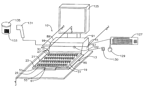
Referring to the embodiment of Figure 12A, system 10 may include a server
107 operably connected to PLC 79 via data port 109 and communication link 111.
In
the embodiment, controller 17 includes both PLC 79 and server 107 operatively
connected thereto. Server 107 may include memory 113 with a program of
instructions 115 residing in memory 113. Server 107 is representative of any
data
management system operated by a pharmacy, hospital, long-term care facility,
or
other operator for purposes of managing information related to dispensing of
medicaments 11. Communication link 111 may be any link capable of transmitting
data and other information. Link 111 may, for example, comprise a dedicated
land
line, wireless link, ethernet, interne, intranet, local area network (LAN), or
other
suitable connection enabling data transmission between PLC 79 and server 107.
Server 107 is preferably an off-the-shelf computer representative of any
suitable data-
management controller. It is envisioned that holder 13 can be connected
directly to
server 107 without a docking station 15, for example through a suitable
communication link.
In a further illustrative embodiment represented by Figure 12B, system 10'
includes an on-board computer 117 within docking station 15, 15' housing 89
and
computer 117 serves as controller 17. Computer 117 includes a program of
instructions 119 residing in memory 121 which are operable to selectively
energize
and operate the indicators 49 to indicate the cell 33 into which one or more
medicament(s) is/are to be placed. In this embodiment, computer 117 is linked
to
automated dispensing machine 45 via communication link 123 and server 124.
Communication link 123 may be of the type as described previously in
connection
with link 111 and server may be a pharmacy information system server provided
to
manage phamiacy workflow generally. Overall activation of indicators 49 is
provided
by computer 117 in this example. System 10' is otherwise identical to system
10 and
the description of system 10 is incorporated by reference with respect to
system 10'.
Each docking station 15, 15' further preferably includes a video display 125,
keyboard 127, and mouse 129 permitting a technician or pharmacist to input and
receive information from server 107 or computer 117 of controller 17. A
biometric
identification device 130 may be provided to permit the technician or
pharmacist to be
-18-
CA 02828680 2013-09-27
identified to the system 10 or 10', particularly when logging on to the
system. The
biometric device 130 may be a fmgerprint reader, retina scanner, or other
suitable
device. A bar code scanner 131 is preferably operably connected to controller
17.
Video display 125 is preferably a touch screen display permitting a technician
to input
information to controller 17 by simply touching her finger on a desired
portion of the
display 125. Bar code scanner 131 may be any off-the-shelf scanner capable of
reading a bar code 133 on a container 135 provided to hold medicaments 11.
Keyboard 127 may be an off-the-shelf QWERTY-type keyboard 127 permitting a
technician to input information to controller 17 and system 10, 10'.
Figures 7, 8, 9, and 10 illustrate a further holder 13" and docking station
15"
embodiment suitable for use with an item-management system, such as system 10
or
10'. For simplicity and brevity, like reference numbers of holders 13, 13' and
docking
stations 15, 15' are used to identify like parts of holder 13" and docking
station 15"
and the description of holders 13, 13' and docking stations 15, 15' are
incorporated by
reference with respect to holder 13" and docking station 15". The embodiment
of
Figures 7-10 differs from the embodiments of Figures 1-6 because the indicator
or
indicators 49 which are selectively-operable to indicate the holder cell 33
into which
an item is to be loaded are located on a guide 136 associated with docking
station 15".
Use of guide 136 with indicators 49 located thereon enables use of the item
management system with a holder 13" which does not include indicators 49
thereon,
typical of holders presently in use.
Referring further to Figures 7-10, holder 13" includes body 19, top and bottom
sides 21, 23, sides 25-31, cells 33 (including inlet and outlet openings 37,
39), legs 51,
53, shuttle member 55. An identification element 81 of the type previously
described
is preferably provided on body 19. An alignment pin receiver 63 may be
provided to
receive pin 65 of docking station 15" to position holder 13" at docking
station 15".
Exemplary docking station 15" includes detector 83, housing 89 with walls 91-
101,
lamp 102, power supply 103, and ports 105, 109, and is provided with a video
display
125, keyboard 127, mouse 129, biometric identification device 130, and bar
code
scanner 131 for the purposes described in connection with docking stations 15,
15'.
Docking station 15" includes a guide 136 attached to housing front wall 99.
-19-
CA 02828680 2013-09-27
Guide 136 is preferably a planar member located in a plane above a holder 13"
docked at docking station 15" beneath guide 136. Guide 136 is provided with
openings, each of which is identified by reference number 138 for brevity. In
the
example, guide 136 is provided with 64 total openings 138 grouped in four rows
of
openings 138. This opening 138 pattern is identical to the pattern of cells 33
in holder
15". This opening 138 pattern is such that the openings 138 in guide 136 are
in
registry and alignment with the corresponding cells 33 of holder 13" when
holder 13"
is docked at docking station 15". This arrangement allows a technician to
rapidly and
accurately load each cell 33 of holder 13" by inserting a medicament through
the
appropriate opening 138 in guide and into the corresponding cell 33 during
holder 13"
loading.
Indicators 49 on guide 136 are proximate each opening 138 to indicate to the
technician, upon activation, which opening 138 a medicament 11 or other item
is to be
inserted. Indicators 49 may, for example, be a single lamp (preferably an LED)
as
illustrated in Figures 1, 3-4, 6-7, and 9, a multi-colored LED as illustrated
in Figures
11A-11C, or plural indicators 49 as illustrated in Figure 11D, or another
indicator
type. Human-readable indicia 140 is preferably provided on guide 136 so that
each
opening 138 on guide 136 has the same indicia 140 as indicia 47, 211 on holder
13"
and exception storage apparatus 43. Indicia 140 further assists the technician
to
ensure that the correct medicament 11 is loaded into the correct guide 136
opening
138. Guide 136 indicators 49 are connected to PLC 79 through appropriate
conductors (not shown) permitting selective energizing and operation of
indicators 49
to indicate the opening 138 through which each medicament 11 is to be loaded.
Guide 136 may be made of any suitable material such as metal, plastic,
laminate or a
combination of materials.
Docking station 15" is otherwise identical to docking station 15 previously
described and illustrated and the description of docking station 15 is
incorporated by
reference. Controller 17, as previously described, controls operation of
docking
station 15" and indicators 49 on guide 136 and holder 13", docking station
15", and
controller 17 may be used as part of an item-management system, such as system
10
or 10' (Figures 12A, 12B).
-20-
CA 02828680 2013-09-27
Figures 14-17 are exemplary screen displays of a type which could be
displayed to a technician or pharmacist on display 125 for purposes of
implementing
system 10 or 10' using holder 13, 13', or 13" and docking station 15, 15', or
15".
The screen displays of Figures 14-17 are intended to represent non-limiting
examples
as the type and number of screen displays can be modified and the information
provided in the screen displays may be customized to meet the needs of the
particular
pharmacy, hospital, long-term care facility or other operator. For convenience
and
brevity, the screen displays of Figures 14-17 are described in connection with
system
including holder 13 and docking station 15, it being understood that the
screen
10 displays and methods of implementing system 10 are applicable for use
with system
10' or with holder 13', 13" and docking station 15', 15".
Referring to the screen displays of Figures 14-17, a technician or registered
pharmacist initiates use of system 10 by logging on to the system 10.
preferably at
docking station 15. Preferably, loading of holder 13 is performed by a
technician
while verification of the loaded holder 13 is performed by a registered
pharmacist.
Referring to Figure 14, the technician is initially presented with a log-on
screen 137 displayed on video display 125. The technician logs on to the
system 10
by keying his or her password into the password field 139 using keyboard 127
and
selecting the ENTER icon 141. Alternatively. the technician could utilize
biometric
device 130 to identify herself to the system 10. The technician's password
information is transmitted to server 107 (or server 124 in system 10'),
whereupon it is
determined that the technician is an authorized user.
If a holder 13 is not already docked at docking station 15 as shown in Figures
1-3 (or is not in wireless communication with docking station 15' as in Figure
6),
a further screen (not shown) may be displayed on video display 125 prompting
the
technician to dock a holder 13 at docking station 15. In the example of
Figures 1-3.
holder 13 is shown docked at docking station 15 by insertion of pin 65 in
receiver 63,
thereby positioning holder 13 to form an electrical connection between holder
contacts 67, 69 and docking station contacts 71, 73. Identification element
detector
83 identifies the unique identifier element embedded in holder 13. Detector 83
preferably detects an RFID-type identification element 81 to identify holder
13 to
-21-
CA 02828680 2013-09-27
system. If the docked holder 13 is recognized by system 10 (or if wireless-
type holder
13' is recognized by system 10), indicator lamp 102 is activated to inform the
technician that the system 10 is in a ready state. Proximity detector 66 may
also
indicate to controller 17 that holder 13 is properly docked at docking station
15.
Referring next to Figure 15, if the technician is authorized and if holder 13
is
docked and recognized, then a holder-loading screen 143 is displayed on video
display 125. Holder-loading screen 143 provides information for loading each
medicament 11 into the correct cell 33.
Information which may be presented on holder-loading screen 143 can include
an identification field 145 identifying the operator name (e.g., Nowtime
Pharmacy),
technician name, and date and time-of-day on which holder 13 is being loaded.
Additional information which may be displayed in connection with screen 143 is
the
holder identifier 147 and transaction code 149 which indicates the transaction
corresponding to loading of the holder 13 for record-keeping purposes.
Preferably,
the transaction number and all other information relating to loading and
verification of
holder 13 is stored in a database on server 107 or 124. Holder identifier 147
may be
any symbol or group of symbols capable of distinguishing one holder 13 from
another
holder 13. In the example, holder identifier 137 is identical to the
identifier embedded
in RFID tag-type identification element 81. In the example, the holder
identifier 147
is the number 2. A unique identifier 147 can be important if more than one
identical
holder 13 is used by the pharmacy, hospital, long-term care provider or other
operator.
Referring further to Figure 15, holder-loading screen 143 includes information
151 required for loading of cells 33 of holder 13. Preferably, information 151
is
displayed in the form of a graphical user interface (GUI), thereby
facilitating ease of
use by the technician. In the example, information 151 includes a select field
152, a
cell location field 153, a medication type field 155, a dosage strength field
157, an
NDC number 159 field, a shelf location 161 field, and a status 163 field. In
the
example, information 151 is displayed for each medicament 11 to be loaded into
holder 13. In the example of Figure 15, three medicament 11 types, namely,
Cardura
tablets, Azithrmycin tablets, and Coumadin tablets are to be loaded into
holder 13.
The cell location field 153 identifies the cell 33 into which medicament 11 is
-22-
CA 02828680 2013-09-27
to be loaded by referencing the human-readable indicia 47 associated with the
designated cell 33. In the example, Cardura tablets are to be loaded into
cells of
holder 13 associated with the human-readable indicia 47 represented by numbers
"1,
3, 6, 9, 12, 15, 18, 21, 24, 27" while the other medicaments are to be loaded
into the
other cells 33 of holder 13 identified in the cell location field 153. The
ordering of the
medicaments 11 is determined by the order in which the medicaments 11 are
required
in order to load each container or containers (e.g., a vial, bottle, blister
package, or
pouch package) for each prescription order or dispense request. For example,
server
107 may order the medicaments 11 presented on screen 143 based on the sequence
in
which prescription orders or dispense requests are to be filled for more than
one
patient or may order the medicaments 11 presented on screen 143 based on a
drug
regimen for a single patient, for example, ordering the medicaments by the
time of
day the medicaments 11 are to be taken by the patient (e.g., breakfast, lunch,
and
dinner). The slow mover medicaments 11 indicated on screen 143 may be arranged
and ordered for serial dispensing (i.e., one-after-the-other) or may be
arranged and
ordered to alternate with medicaments dispensed from other storage apparatus
(e.g.,
cassettes, cells, canisters, etc.) within automated dispensing machine 45.
The medication type field 155 and dosage strength field 157 information refers
to the type and strength of the medicament 11, while the NDC number field 159
information refers to the 10-digit National Drug Code (NDC) number for the
specific
medicament 11 called for by the prescription order or dispense request.
The shelf location field 161 information refers to the shelf location of the
pharmacy, hospital, long-term care facility, or the like at which the
medicament
container, for example representative container 135 (Figure 1), holding a
medicament
11 is located. This information is provided to assist the technician in
retrieving the
container 135 from storage. In the example, fictitious alpha-numeric shelf
locations
are displayed.
As illustrated in Figures 1 and 7, it is envisioned that the technician will
scan
the bar code 133 on the container 135 with bar code scanner 131. Program of
instructions 115 running on server 107 can then verify that the correct
container 135
has been selected from storage based on information contained in bar code 133.
The
-23-
CA 02828680 2013-09-27
technician can also verify that the correct medicament container 135 has been
selected
by comparing the medication type 155, strength 157, and human-readable NDC
information 159 on the screen 143 with human-readable information on the label
for
container 135.
The status information field 163 indicates the status of the holder-loading
process. Selection of each medicament 11 for loading can be made simply by
touching the technician's finger on the row 165 of touch-screen video display
125
associated with one medicament 11 or by selecting the row 165 with another
input
device, such as keyboard 127 and mouse 129. In the example of Figure 15, the
technician is in the process of loading Cardura tablets into cells 33. This is
indicated
by the row 165 associated with Cardura tablets having been selected as
indicated by
the X character in the select field 152 and the IN-PROCESS text in status
information
field 163. The row 165 associated with the Azithrmycin tablets indicates
FILLED in
the status information field 163 indicating that loading of the Azithrmycin
tablets has
been previously completed. The row 165 associated with the Coumadin tablets
has
not yet been selected as indicated by the UNFILLED indication in field 153.
PLC 79 (or computer 117 in system 10') selectively activates the indicator 49
for each cell 33 into which the medicament 11 is to be loaded once the
appropriate
row 165 associated with the medicament is selected. This pick-to-light feature
enables the technician to load medicaments 11 without any necessity for
reliance on
written loading instructions. Thus, in the example of Figure 15, the indicator
49,
preferably an LED lamp, associated with each of cells 33 indicated by the
human-
readable indicia 47 "1, 3, 6, 9, 12, 15, 18, 21, 24, 27" is energized to tell
the
technician to load a Cardura tablet into each of these cells 33. Each
indicator 49
associated with each other cell 33 of holder 13 is not activated. Activation
of only
each indicator 49 associated with the cell to be loaded is referred to herein
as selective
indicator 49 activation or operation.
Once all cells 33 associated with a row 165 are filled, the technician then
selects the next row 165 of medicaments to be filled and proceeds to load
holder 13 as
directed by indicators 49. Selection can again be accomplished by touching the
technician's finger on the row 165 of touch-screen video display 125
associated with
-24-
CA 02828680 2013-09-27
the next medicament 11 to be loaded in holder 13 or by selecting the row 165
with the
keyboard 127 or mouse 129. The indicator or indicators 49 previously activated
are
deactivated and the appropriate indicators 49 for the next medicament 11 to be
loaded
are activated. This process is repeated until all medicaments 11 have been
loaded in
holder 13 as called for by screen 143.
Once all cells 33 of holder 13 are loaded as required by holder-loading screen
143, the technician clicks on, or otherwise selects, the HOLDER FILLED icon
167.
Selection of icon 167 sends a signal to server 107 (or server 124 in system
10'
indicating that loading of holder 13 has been completed. Each loaded holder 13
can
subsequently be verified by a registered pharmacist prior to loading of
medicaments
11 from loaded holder 13 into automated dispensing machine 45.
Referring now to Figure 13, a storage cabinet 169 may optionally be provided
to store one or more holder 13, 13a, 13b, and 13c thereby facilitating loading
and
verification of multiple holders. In the example, each holder represented by
reference
numbers 13a, 13b and 13c has structure identical to holder 13. Loaded holders
13,
13a, 13b, and 13c may be stored in cabinet 169 after loading and before
verification
or may be stored in cabinet 169 after verification by a registered pharmacist
and
before loading of the verified medicaments 11 into exception storage apparatus
43 of
automated dispensing machine 45.
If provided, storage cabinet 169 includes top and bottom walls 171, 173,
sidewalls 175, 177, and a front opening 179 through which holders (e.g.,
holder 13)
are placed into cabinet 169. Stacked opposed slot pairs 181,183 may be
provided to
receive the bottom 23 of each holder 13 permitting holders 13, 13a, 13b, and
13c to be
stored in cabinet 169.
As already noted, each loaded holder 13 can be verified by a registered
pharmacist to ensure that each cell 33 has been loaded with the correct
medicament
11. Figure 16 shows an exemplary holder-verification screen 185 which
corresponds
to the holder-loading screen 143 for that holder 13. Holder-verification
screen 185
includes information 187 required for verification of the medicaments 11
loaded into
cells 33 of holder 13. This information is essentially identical to that
displayed in
connection with holder-loading screen 143. For convenience and simplicity,
-25-
CA 02828680 2013-09-27
reference numbers of information displayed on holder-loading screen 143 are
used
again to identify corresponding fields of information on holder-verification
screen
185.
As with the holder-loading screen 143, an identification field 145 can be
provided to identify the operator name (e.g., Nowtime pharmacy), name of the
pharmacist responsible for medicament 11 verification, and the date and time-
of-day
on which holder 13 is verified. The holder identifier 147 and transaction code
149 are
also preferably displayed for the same purpose as described in connection with
the
holder-loading screen 143.
Preferably, information 187 is again displayed in the form of a graphical user
interface (GUI), thereby facilitating ease of use by the verifying pharmacist.
In the
example, the displayed information 187 again includes a select field 152, a
cell
location field 153, a medication type field 155, a dosage strength field 157,
an NDC
number field 159, a shelf location field 161, and a status information field
163
including the information described in connection with holder-loading screen
143. In
the example, information 187 is again displayed for each medicament 11 to be
loaded
into holder 13. In the example of Figure 16, the Cardura tablets, Azithrmycin
tablets,
and Coumadin tablets previously loaded into cells 33 of holder 13 are
presented for
verification by the pharmacist.
In order to verify that each cell 33 holds the correct medicament 11, the
pharmacist simply selects the row 165 to be verified. Selection is
accomplished by
touching the touch screen display 125 on row 165 or by selecting row 165 with
the
keyboard 127 or mouse 129. The status information field 163 again indicates
the
status of the holder-verification process.
Referring further to Figure 16, the screen display 185 shows an example of
displayed information for verification that the Cardura tablets have been
correctly
loaded into the cells 33 indicated by the human-readable indicia 47 "1, 3, 6,
9, 12, 15,
18, 21, 24, 27" located on holder 13. Selection of the Cardura tablets for
verification
is indicated in the example by the row 165 associated with Cardura tablets
having
been selected as indicated by the X character in the select field 152 and the
IN-
PROCESS text in status information field 163. The row 165 associated with the
-26-
CA 02828680 2013-09-27
Azithrmycin tablets indicates VERIFIED in the status information field 163
indicating
that verification of the Azithrmycin tablets has been completed. The row 165
associated with the Coumadin tablets has not yet been selected for
verification as
indicated by the UN-VERIFIED indication in field 163. A selected row 165 can
also
be highlighted to facilitate identification of the row 165 then being
verified.
Referring next to Figure 17, a further verification screen display 186 may be
provided to assist the pharmacist with the verification process. As each row
165 is
selected, a medicament-specific verification screen 186 may be displayed. In
the
example, screen 186 displays the row 165 being verified including the cell
location
field 153, medication type field 155, dosage strength field 157, NDC number
field
159, shelf location field 161, and status information field 163. Screen 186
also
displays a reference image of the physical appearance of the medicament 188
together
with a word description 190 of the physical appearance of the medicament 11.
In this
example of the Cardura medicaments 11, the word description 190 is white
oblong
tablet. A screen display similar to display 186 of Figure 17, including a
reference
image 188 and word description 190, may be displayed to the technician during
the
holder-loading process associated with screen 143 to assist the technician in
placing
the correct medicament(s) 11 into each cell 33.
Upon selection of a row 165, PLC 79 of controller 17 again selectively
activates each indicator 49, preferably an LED lamp, for each cell 33 to be
verified by
the pharmacist. As with the loading process, this pick-to-light capability
enables the
pharmacist to rapidly confirm that the correct medicament 11 has been loaded
into the
correct cell 33 without the necessity for reliance on written verification
instructions.
The pharmacist can quickly compare the physical appearance of each medicament
11
in each indicated cell 33 without the necessity of reliance solely on written
instructions. This process is facilitated by presentation of screen 186 and
the
reference image and description information 188, 190 as the pharmacist can
quickly
compare the appearance of the medicament 11 on screen 186 with the appearance
of
the medicament(s) 11 in each cell 33 associated with an activated indicator
49.
Thus, in the verification example of Figures 16-17, each indicator 49
associated with each of cells indicated by the human-readable indicia 47 "1,
3, 6, 9,
-27-
CA 02828680 2013-09-27
12, 15, 18, 21, 24, 27" into which Cardura tablets was to be loaded, is
activated by
PLC 79 of controller 17 (or computer 117 in system 10') during the
verification
process. Each other indicator 49 is inactive.
If screen 186 is provided, selection of the DONE icon 192 returns the
pharmacist to screen 185 for selection of the next medicament 11 to be
verified.
Once all cells 33 associated with a row 165 are verified, the technician then
selects the
next row 165 of medicaments to be verified and proceeds to verify the
medicament(s)
in each cell 33 as directed by indicators 49. The indicator or indicators 49
previously
activated are deactivated and the appropriate indicators 49 for the next
medicament 11
10 are activated. This process is repeated until all medicaments 11 have been
verified
as called for by screen 185.
Once all rows 165 and medicaments 11 are verified, the pharmacist selects the
HOLDER VERIFIED icon 189. Selection of icon 189 sends a signal to server 107
of
system 10 (or server 124 of system 10') indicating to system 10 that holder 13
has
been fully verified and that the medicament 11 contents are in the correct
cells 33
ready for use with automated dispensing machine 45. A record may be made of
the
verified medicament 11 contents of holder 13 cells 33 which may be stored in a
database residing on server 107 (or server 124). Such a record is useful in
further
confirming that the correct medicaments 11 were loaded in holder 13. Each
verified
holder 13 can then be stored in cabinet 169 awaiting use, or the holder 13 and
its
medicament 11 contents can be taken directly to automated dispensing machine
45 for
immediate loading of medicaments 11 into exception storage apparatus 43.
Referring now to Figures 18-20, there is shown an exemplary automated
dispensing machine 45 and exception storage apparatus 43 which may be quickly
and
accurately loaded with medicaments 11 using holder 13 or 13' or 13".
Dispensing
machine 45 includes a cabinet 191 with top and bottom walls 193, 195 and left
and
right sidewalls 197, 199. A touch-screen video display 201 is mounted to
sidewall
199. Display 201 includes controls permitting a technician or pharmacist to
control
operation of dispensing machine 45 and to receive information about the status
of the
medicament filling process.
-28-
CA 02828680 2013-09-27
-
Exemplary dispensing machine 45 includes twenty pull-out drawers of which
drawers 203 are exemplary. In the example, drawers 203 are organized into five
rows
of four drawers 203. Each drawer 203 supports a plurality of removable
cassette-type
storage apparatus (not shown), each of which stores a large quantity of bulk-
form
medicaments 11. The cassettes can be replenished as medicaments 11 stored
therein
are depleted.
Exemplary dispenser 45 further includes a pair of doors 205, 207 which cover
exception storage apparatus 43 as shown in Figure 18 and which can be opened
as
shown in Figures 19-20. As previously described, exception storage apparatus
43
may be provided to store and to dispense "slow mover" medicaments 11 loaded
therein. In the example, dispenser 45 includes a single exception storage
apparatus 43.
However, any number of exception storage apparatus 43 may be provided based on
the needs of the operator.
In the example, exception storage apparatus 43 is a drawer or tray-like device
which can be pulled out from cabinet 191 as shown in Figures 19-20. When in
the
state of Figures 19-20, automated dispensing machine 45 is temporarily shut
down
and is out of service and unavailable to fill prescription orders and dispense
requests
while exception storage apparatus 43 is pulled out from cabinet 191.
Therefore, it is
important to load exception storage apparatus 43 as promptly as possible to
return
dispensing machine 45 to service.
The exception storage apparatus 43 shown in Figures 19-20 can be described
as having a somewhat flat and narrow configuration with a plurality of cells
41
provided therein. Each cell 41 of exception storage apparatus 43 is capable of
storing
one medicament 11, or a small quantity of medicaments 11 as illustrated in
Figures
21A-22. In the example, cells 41 include 64 total cells grouped in four rows
of 16
cells.
Cells 41 are indexed for movement along a track (not shown) in exception
storage apparatus 43. Cells 41 are indexed forward along the track toward an
opening
(not shown) in the bottom of apparatus 43 so that the contents of each cell 41
fall
through a cell bottom opening (not shown) and to a packaging device within
dispensing machine 45 through chutes, hoppers or other guide structure, or by
a
-29-
CA 02828680 2013-09-27
mechanical device such as an auger. Medicaments 11 may be discharged from
cells
41 by any other suitable means including a movable gate (not shown) over a
cell
bottom outlet (not shown), or by a solenoid, air-powered actuator, air-jet, or
mechanical arm which ejects the medicament through an upper cell inlet 209 of
the
type shown in Figure 19A. The medicaments 11 fall via chutes, guides to a
packaging
device or are directed to packaging device by mechanical means (e.g. an
auger).
In the example, automated dispensing machine 45 includes a pouch-package-
type packaging apparatus (not shown) within a lower portion of cabinet 191.
Alternatively, packaging apparatus capable of packaging medicaments 11 into
other
container types (e.g., bottles, vial, blister packages) may be utilized. A
pouch-
package-type packaging device includes a form-fill-seal packaging device. A
"form-
fill-seal" packaging device forms a package (i.e., a pouch) in a web of
packaging
material, fills the package with the medicament(s), and seals the package
forming a
plurality of discrete packages, or pouches.
In the example, one or more medicament 11 discharged from the cassette-type
storage apparatus (not shown) or exception storage apparatus 43 is loaded into
separate pouches 202 formed (e.g., by heat-sealing or sonic welding) in a web
of
packaging material 204 as illustrated in Figure 22. Information can be printed
on
each pouch 202 by a printer (not shown) associated with dispenser 45 and such
information can include the patient's name 206, medicament name and quantity
208,
prescription number 210, date 212, instructions for taking the medicament 214
(such
as time of day the medicament is to be taken) and machine-readable indicia 216
(such
as a bar code) representative of the aforesaid information. Pouch packages are
ideal
for use in administering medication regimens because the exact medicaments to
be
taken at a given time can be packaged together in a single pouch, and the
pouches can
be organized and labeled in the exact order in which each medicament is to be
taken,
for example, morning, noon and evening. An exemplary automated dispensing
machine 45 is a model ATP 320, 371, or 384 dispensing machine available from
Chudy Group, LLC of Powers Lake, Wisconsin.
-30-
CA 02828680 2013-09-27
Transfer of medicaments 11 from holder cells 33 to exception storage
apparatus will now be described in connection with Figures 21A-21C. In the
example,
cells 33 of holder 13 are positioned and arranged so that they have a pattern
which is
identical to that of cells 41 in exception storage apparatus 43. Holder 13,
therefore,
can be placed directly on top of exception storage apparatus 43 as shown in
Figure 20
and Figures 21A-21C with each cell 33 and 41 completely aligned and in
registry. In
the example, holder 13 and exception storage apparatus 43 each have 64 total
cells 33,
41 grouped in four rows of 16 cells. Human-readable indicia 211 is preferably
provided on exception storage apparatus 43 (Figure 19A) so that each cell 33
on
holder 13 has the same indicia 47 as indicia 211 on exception storage
apparatus 43.
The cell 33 pattern and indicia 47 of holder 13 is most preferably identical
to the cell
41 pattern and indicia 211 of exception storage apparatus 43.
Referring again to Figures 20 and 21A-21C, the verified holder 13 is taken to
exception storage apparatus 43 of dispensing machine 45 by a technician or
pharmacist. Holder 13 is set on top of exception storage apparatus 43. Legs
51, 53
position holder 13 over exception storage apparatus 13 as shown. for example,
in
Figures 21A-21C to ensure that holder 13 is in the correct orientation on
exception
storage apparatus 43 with correct alignment of cells 33, 41. Once aligned,
holder 13
is initially in the position shown in Figure 21A.
At this point in the process, identification element 81 is detected by
detector
84 of dispensing machine 45. If the correct holder 13 is positioned over
exception
storage apparatus 43, the technician/pharmacist is given a prompt signal by
video
display 201. If an incorrect holder 13 is positioned over exception storage
apparatus
43, then display 201 prompts the technician/pharmacist to not transfer the
medicaments 11 and may present an error message and/or alarm. In addition,
system
10 or 10' may deactivate dispenser 45 preventing dispenser 45 operation until
the
correct holder 13 is in place or the technician/pharmacist overrides the
system 10, 10'.
Prior to medicament 11 transfer and as shown in Figure 21A, shuttle member
55 is in its "closed" position with cell 33 outlets 39 covered by shuttle
member 55.
Medicaments 11 cannot exit cells 33 in this closed position.
-31-
CA 02828680 2013-09-27
_
_
Next, and as shown in Figure 21B, the technician grasps pull 61 and moves
shuttle member 55 in the direction of arrow 217. Movement of shuttle member 55
in
the direction of arrow 217 partially opens cell outlets 39 as openings 59 in
shuttle
member 55 are aligned with cell outlets 39. As a result, medicaments 11 begin
to fall
by means of gravity into the aligned cells 41 of exception storage apparatus
43.
Finally, and as shown in Figure 21C, the technician moves shuttle member 55
fully in the direction of arrow 217 by means of pull 61 to fully align
openings 59 in
shuttle member 55 with cell outlets 39. Cells 33 are fully open in this
position
causing medicaments 11 in cells 33 to fall into the corresponding cells 41 of
exception
storage apparatus 43. Exception storage apparatus is now correctly loaded and
is
ready for dispensing and packaging of the slow mover medicaments 11 stored in
cells
41. This loading process shown in Figures 21A-21C is very rapid (less than one
minute) and enables automated dispensing machine 45 to be quickly returned to
service.
Systems 10, 10' accurately and rapidly enable loading of medicaments 11 in
the exact order in which the medicaments 11 are to be loaded into exception
storage
apparatus 43. The medicaments 11 are rapidly verified by the system 10, 10'
and
docking station 15 in a way which is not possible based solely in reliance on
written
instructions. This is because selective operation of the indicators 49 permits
pharmacy personnel to load and verify the contents of holder 13 without having
to
take his or her eyes off of the holder 13 to read instructions. Each exemplary
system
10, 10' therefore, speeds the holder-loading process while at the same time
providing
a high confidence level that each cell 33 and 41 has been loaded with the
correct
medicament 11. Accurate loading of medicaments 11, in tuna provides a better
level
of care for all patients which, of course, is always the primary objective of
any
pharmacy, hospital, long-term care facility or other care-giver.
And, time required for selecting, verifying, and loading medicaments 11 into
the automated dispensing machine is significantly decreased. This frees
pharmacists
to better serve their patients and enables the automated dispensing machine 45
to be
immediately returned to service. The result once again is improved patient
care and
reduced cost of operation to the pharmacy, hospital, long-term care provider
or other
-32-
CA 02828680 2013-09-27
operator.
While the principles of this invention have been described in connection with
specific embodiments, it should be understood clearly that these descriptions
are made
only by way of example and are not intended to limit the scope of the
invention.
-33-