Note: Descriptions are shown in the official language in which they were submitted.
CA 02828870 2013-08-30
WO 2012/121946 PCT/US2012/027075
-1-
METHODS OF FORMING POLYCRYSTALLINE TABLES
AND POLYCRYSTALLINE ELEMENTS AND RELATED STRUCTURES
PRIORITY CLAIM
This application claims the benefit of the filing date of United States Patent
Application Serial Number 13/040,900, filed March 4, 2011, for "METHODS OF
FORMING POLYCRYSTALLINE TABLES AND POLYCRYSTALLINE
ELEMENTS AND RELATED S _______ FRUCTURES."
TECHNICAL FIELD
Embodiments of the present invention relate generally to methods of forming
polycrystalline tables, methods of forming polycrystalline elements, and
related
structures. Specifically, embodiments of the disclosure relate to methods for
attaching fully leached or substantially fully leached polycrystalline tables
to
substrates to form polycrystalline elements, and intermediate structures
related
thereto.
BACKGROUND
Earth-boring tools for forming wellbores in subterranean earth formations
may include a plurality of cutting elements secured to a body. For example,
fixed-cutter earth-boring rotary drill bits (also referred to as "drag bits")
include a
plurality of cutting elements that are fixedly attached to a bit body of the
drill bit.
Similarly, roller cone earth-boring rotary drill bits may include cones that
are
mounted on bearing pins extending from legs of a bit body such that each cone
is
capable of rotating about the bearing pin on which it is mounted. A plurality
of
cutting elements, known in the art as "inserts," may be mounted to each cone
of the
drill bit.
The cutting elements used in such earth-boring tools often include
polycrystalline diamond compact (often referred to as "PDC") cutting elements,
also
termed "cutters," which are cutting elements that include a polycrystalline
diamond
(PCD) material, which may be characterized as a superabrasive or superhard
material. Such polycrystalline diamond materials are formed by sintering and
bonding together relatively small synthetic, natural, or a combination of
synthetic
CA 02828870 2013-08-30
WO 2012/121946
PCT/US2012/027075
-2-
and natural diamond grains or crystals, termed "grit," under conditions of
high
temperature and high pressure in the presence of a catalyst, such as, for
example,
cobalt, iron, nickel, or alloys and mixtures thereof, to form a region of
polycrystalline diamond material, also called a diamond table. These processes
are
often referred to as high temperature/high pressure ("HTHP") processes. The
cutting element substrate may comprise a cermet material, i.e. , a ceramic-
metal
composite material, such as, for example, cobalt-cemented tungsten carbide. In
some instances, the polycrystalline diamond table may be formed on the cutting
element, for example, during the HTHP sintering process. In such instances,
cobalt
or other catalyst material in the cutting element substrate may be swept into
the
diamond grains or crystals during sintering and serve as a catalyst material
for
forming a diamond table from the diamond grains or crystals. Powdered catalyst
material may also be mixed with the diamond grains or crystals prior to
sintering the
grains or crystals together in an HTHP process. In other methods, however, the
diamond table may be formed separately from the cutting element substrate and
subsequently attached thereto.
To reduce problems associated with differences in thermal expansion and
chemical breakdown of the diamond crystals in PDC cutting elements, "thermally
stable" polycrystalline diamond compacts (which are also known as thelinally
stable
products or "TSPs") have been developed. Such a thermally stable
polycrystalline
diamond compact may be formed by leaching catalyst material out from
interstitial
spaces between the interbonded grains in the diamond table. When the diamond
table is folined separately and subsequently attached to a substrate, also
known in
the art as a "reattach" process, inadequate attachment may result in
delamination of
the diamond table from the substrate and premature failure of the cutting
element.
In addition, catalyst material may sweep from the substrate into the
polycrystalline
table during the attachment process, and the polycrystalline table may again
require
leaching to reduce problems associated with differences in rates of thermal
expansion and chemical breakdown of the diamond crystals.
CA 02828870 2015-11-24
-3-
DISCLOSURE OF THE INVENTION
In some embodiments, the disclosure includes a method of forming a
polycrystalline
element, comprising: disposing a first plurality of particles comprising a
superabrasive
material, a second plurality of particles comprising the superabrasive
material, and a catalyst
material in a mold; sintering the first and second pluralities of particles in
the presence of
the catalyst material to form a polycrystalline table comprising a first
region having a first
permeability and at least a second region having a second, greater
permeability, wherein the
first region comprises a first density of superabrasive material and the at
least a second
region comprises a second, lesser density of superabrasive material; at least
substantially
removing the catalyst material from the polycrystalline table; and attaching
the
polycrystalline table to an end of a substrate comprising a hard material and
a flowable non-
catalyst material separate from the catalyst material, the at least a second
region being
interposed between the first region and the substrate, by infiltrating a
portion of the flowable
non-catalyst material from the substrate into interstitial spaces among
interbonded grains of
the superabrasive material of at least the second region of the
polycrystalline table.
In other embodiments, the disclosure includes a method of attaching a
polycrystalline table to a substrate, comprising: forming a polycrystalline
table of
superabrasive material and comprising a first region having a first
permeability and at least a
second region having a second, greater permeability, wherein the first region
comprises a
first density of superabrasive material and the at least a second region
comprises a second,
lesser density of superabrasive material; at least substantially removing
catalyst material
from the polycrystalline table; contacting the polycrystalline table on an end
of a substrate
comprising a hard material and a flowable non-catalyst material separate from
the catalyst
material, the at least a second region being interposed between the first
region and the
substrate; and infiltrating interstitial spaces among interbonded grains of
the superabrasive
material of the at least the at least a second region of the polycrystalline
table with the
flowable non-catalyst material from the substrate.
CA 02828870 2015-11-24
-3a-
In additional embodiments, the disclosure includes a polycrystalline element,
comprising: a substrate comprising a hard material and a flowable non-catalyst
material; and
a polycrystalline table comprising a superabrasive material and having a first
region
exhibiting a first permeability and at least a second region exhibiting a
second, greater
permeability attached to an end of the substrate, the at least a second region
being interposed
between the substrate and the first region, wherein the first region comprises
a first density
of superabrasive material and the at least a second region comprises a second,
lesser density
of superabrasive material; and wherein the flowable non-catalyst material is
separate from a
catalyst material used to catalyze formation of intergranular bonds among
grains of the
superabrasive material of the polycrystalline table and a portion of the
flowable non-catalyst
material from the substrate is resident in interstitial spaces among
interbonded grains of at
least the second region of the polycrystalline table.
BRIEF DESCRIPTION OF THE DRAWINGS
1 5 While the specification concludes with claims particularly pointing out
and distinctly
claiming that which is regarded as the present invention, various features and
advantages of
embodiments of this invention may be more readily ascertained from the
following description
of embodiments of the invention when read in conjunction with the accompanying
drawings, in
which:
CA 02828870 2013-08-30
WO 2012/121946 PCT/US2012/027075
-.4-
FIG. 1 is a partial cut-away perspective view of a cutting element including a
polycrystalline table of the present disclosure;
FIG. 2 illustrates a cross-sectional view of another cutting element including
a dome-shaped polycrystalline table of the present disclosure;
FIG. 3 depicts a simplified view of how a microstructure of a first region of
a
polycrystalline table of the present disclosure may appear under
magnification;
FIG. 4 is a simplified view of how a microstructure of a second region of a
polycrystalline table of the present disclosure may appear under
magnification;
FIG. 5 illustrates a cross-sectional view of a cutting element including
another configuration of a polycrystalline table of the present disclosure;
FIG. 6 depicts a cross-sectional view of a cutting element including another
configuration of a polycrystalline table of the present disclosure;
FIG. 7 is a cross-sectional view of a cutting element including a non-planar
interface design at an interface between a substrate and a polycrystalline
table of the
present disclosure;
FIG. 8 illustrates a cross-sectional view of a cutting element including a
non-planar interface design at an interface between regions within a
polycrystalline
table of the present disclosure;
FIGS. 9A through 9F depict cross-sectional views of non-planar interface
designs that may be used in connection with a polycrystalline table of the
present
disclosure;
FIG. 10 is a cross-sectional view of a mold used in a process for attaching a
polycrystalline table of the present disclosure to a substrate;
FIG. 11 illustrates a cross-sectional view of an intermediate structure in a
process for attaching a polycrystalline table of the present disclosure to a
substrate;
FIG. 12 depicts a simplified view of how a microstructure of a second region
of the intermediate structure shown in FIG. 11 may appear under magnification;
FIG. 13 is a cross-sectional view of a mold used in a process for attaching a
polycrystalline table to a substrate;
FIG. 14 illustrates a cross-sectional view of a mold, similar to the mold
shown in FIG. 10, used in a process for attaching a polycrystalline table of
the
present disclosure to a substrate; and
CA 02828870 2013-08-30
WO 2012/121946 PCT/US2012/027075
-5-
FIG. 15 illustrates a perspective view of an earth-boring tool to which a
cutting element including a polycrystalline table of the present disclosure
may be
attached.
MODE(S) FOR CARRYING OUT THE INVENTION
The illustrations presented herein are not meant to be actual views of any
particular earth-boring tool, cutting element, or bearing, but are merely
idealized
representations that are employed to describe the embodiments of the
disclosure.
Additionally, elements common between figures may retain the same or similar
numerical designation.
The terms "earth-boring tool" and "earth-boring drill bit," as used herein,
mean and include any type of bit or tool used for drilling during the
foimation or
enlargement of a wellbore in a subterranean formation and include, for
example,
fixed-cutter bits, roller cone bits, percussion bits, core bits, eccentric
bits, bicenter
bits, reamers, mills, drag bits, hybrid bits, and other drilling bits and
tools known in
the art.
As used herein, the term "polycrystalline table" means and includes any
structure comprising a plurality of grains (i.e., crystals) of material (e.g.,
superabrasive material) that are bonded directly together by inter-granular
bonds.
The crystal structures of the individual grains of the material may be
randomly
oriented in space within the polycrystalline material.
As used herein, the terms "inter-granular bond" and "interbonded" mean and
include any direct atomic bond (e.g., covalent, metallic, etc.) between atoms
in
adjacent grains of superabrasive material.
The term "sintering," as used herein, means temperature driven mass
transport, which may include densification and/or coarsening of a particulate
component, and typically involves removal of at least a portion of the pores
between
the starting particles (accompanied by shrinkage) combined with coalescence
and
bonding between adjacent particles.
As used herein, the terms "nanoparticle" and "nano-size" mean and include
particles (e.g., grains or crystals) having an average particle diameter of
500 nm or
less.
CA 02828870 2013-08-30
WO 2012/121946 PCT/US2012/027075
-6-
As used herein, the term "material composition" means the chemical
composition and microstructure of a material. In other words, materials having
the
same chemical composition but a different microstructure are considered to
have
different material compositions.
As used herein, the term "tungsten carbide" means any material composition
that contains chemical compounds of tungsten and carbon, such as, for example,
WC, W2C, and combinations of WC and W2C. Tungsten carbide includes, for
example, cast tungsten carbide, sintered tungsten carbide, and
macrocrystalline
tungsten carbide.
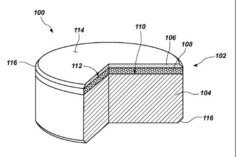
Referring to FIG. 1, a partial cut-away perspective view of a cutting
element 100 including a polycrystalline table 102 is shown. The
polycrystalline
table 102 of the cutting element 100 is attached to an end of a substrate 104.
The
polycrystalline table 102 may be formed separately from the substrate 104 and
subsequently be attached to the substrate 104 in a reattach process. The
polycrystalline table 102 comprises a first region 106 having a first
permeability and
a second region 108 having a second, greater permeability. The second region
108
of the polycrystalline table 102 may be proximate the substrate 104, and the
first
region 106 may be disposed on an end of the second region 108 opposing the
substrate 104. Thus, the second region 108 may be interposed between the first
region 106 and the substrate 104. The polycrystalline table 102 may be
attached to
the substrate 104 at an interface 110. Thus, the interface 110 may comprise a
boundary between the second region 108 and the substrate 104. The first region
106
may form a boundary with the second region 108 at another interface 112 within
the
polycrystalline table 102. In some embodiments, a surface of the first region
106
may form a cutting face 114 of the polycrystalline table 102.
The cutting element 100 may be formed as a generally cylindrical body.
Thus, the substrate 104 may comprise a cylinder and the polycrystalline table
102
may comprise another cylinder or disc attached to an end of the substrate 104.
The
cylindrical substrate 104 may have a circular cross-section. In some
embodiments, a
chamfer 116 may be formed around the peripheral edges of the polycrystalline
table 102, the substrate 104, or both.
The polycrystalline table 102 may comprise a superabrasive, sometimes used
interchangeably to mean "superhard," polycrystalline material. For example,
the
CA 02828870 2013-08-30
WO 2012/121946 PCT/US2012/027075
-7-
superabrasive material may comprise synthetic diamond, natural diamond, a
combination of synthetic and natural diamond, cubic boron nitride, carbon
nitrides,
and other superabrasive materials known in the art. Individual grains of the
superhard material may form inter-granular bonds to form a superabrasive
polycrystalline material.
Typically, a superabrasive polycrystalline material is fonned by sintering
particles of superabrasive material in the presence of a catalyst material
using a
high-temperature/high-pressure (HTHP). Suitable catalyst material may include,
for
example, an alloy (e.g., cobalt-based, iron-based, nickel-based, iron and
nickel-based, cobalt and nickel-based, and iron and cobalt-based) or a
commercially
pure element (e.g., cobalt, iron, and nickel) that catalyzes grain growth and
inter-granular bonding. After formation of the superabrasive polycrystalline
material, catalyst material may remain in interstitial spaces among the
interbonded
grains of superabrasive material foiming a polycrystalline structure.
The substrate 104 may comprise a hard material suitable for use in
earth-boring applications. For example, the hard material may comprise a
ceramic-metal composite material (i.e., a "ceimet" material) comprising a
plurality
of hard ceramic particles dispersed throughout a metal matrix material. The
hard
ceramic particles may comprise carbides, nitrides, oxides, and borides
(including
boron carbide (B4C)). More specifically, the hard ceramic particles may
comprise
carbides and borides made from elements such as W, Ti, Mo, Nb, V, Hf, Ta, Cr,
Zr,
Al, and Si. By way of example and not limitation, materials that may be used
to
form hard ceramic particles include tungsten carbide, titanium carbide (TiC),
tantalum carbide (TaC), titanium diboride (TiB2), chromium carbides, titanium
nitride (TiN), aluminum oxide (A1203), aluminum nitride (AIN), and silicon
carbide
(SiC). The metal matrix material of the ceramic-metal composite material may
include, for example, cobalt-based, iron-based, nickel-based, iron and nickel-
based,
cobalt and nickel-based, and iron and cobalt-based. The matrix material may
also be
selected from commercially pure elements, such as, for example, cobalt, iron,
and
nickel. As a specific, non-limiting example, the hard material may comprise a
plurality of tungsten carbide particles in a cobalt matrix, known in the art
as
cobalt-cemented tungsten carbide.
CA 02828870 2013-08-30
WO 2012/121946 PCT/US2012/027075
-8-
Referring to FIG. 2, another cutting element 100', such as, for example, an
insert for a roller cone in a roller cone earth-boring drill bit, including a
dome-shaped polycrystalline table 102 is shown. The polycrystalline table 102
of
the cutting element 100' is attached to an end of a substrate 104. The
polycrystalline
table 102 may be formed separately from the substrate 104 and subsequently be
attached to the substrate 104 in a reattach process. The polycrystalline table
102
includes a first region 106 having a first permeability and a second region
108
having a second, greater permeability. The second region 108 may be interposed
between the first region 106 and the substrate 104. The substrate 104 may
comprise
an intermediate region 118 proximate the second region 108 and forming a
boundary
with the second region 108 at the interface 110 between the polycrystalline
table 102
and the substrate 104. The intennediate region 118 may comprise a layer or
stratum
of material between the polycrystalline table 102 and the remainder of the
substrate 104. The intermediate region 118 may comprise a combination of the
superabrasive material of the polycrystalline table 102 and the hard material
of the
remainder of the substrate 104. Thus, the intermediate region 118 may enhance
the
attachment strength of the polycrystalline table 102 to the substrate 104 by
providing
a more gradual transition between the materials thereof.
The polycrystalline table 102 may comprise a dome shape, such as, for
example, a hemisphere. The polycrystalline table 102 may comprise a hollow
dome
shape, as shown. The substrate 104 may comprise a corresponding dome-shaped
protrusion that contacts the polycrystalline table 102 at the interface 110
therebetween. A remainder of the substrate 104 may be cylindrical in shape. In
other embodiments, the polycrystalline table 102 may comprise a solid dome
disposed on a cylindrical substrate 104. In still other embodiments, the
polycrystalline table 102 and the cutting element 100 may have other forms,
shapes,
and configurations known in the art, such as, for example, chisel-shaped,
tombstone,
etc.
Referring to FIG. 3, a simplified view of how a microstructure of a first
region 106 of a polycrystalline table 102, such as the first regions 106 shown
in
FIGS. 1, 2, and 5 through 9F, may appear under magnification is shown. The
first
region 106 may comprise a bi-modal grain size distribution, including larger
grains 120 and smaller grains 122 of superabrasive material. In other
embodiments,
CA 02828870 2013-08-30
WO 2012/121946 PCT/US2012/027075
-9-
the first region 106 may comprise a mono-modal grain size distribution or a
multi-modal grain size distribution other than bi-modal (e.g., tri-modal,
quinti-modal, etc.). A multi-modal grain size distribution may enable the
grains 120
and 122 to be more densely packed (i.e., relatively smaller grains 122 may
occupy
portions of the interstitial spaces among larger grains 120 that would
otherwise be
devoid of superabrasive material), resulting in a higher density of
superabrasive
material within the first region 106. In some embodiments, the first region
106 may
include at least some nano-sized grains (i.e., grains having an average
particle
diameter of 500 nm or less) of superabrasive material. For example, the
smaller
grains 122 in the bi-modal grain size distribution may comprise nano-sized
grains.
The larger grains 120 may have an average grain size of, for example, greater
than
51õtm, and the smaller grains 122 may have an average grain size of, for
example,
less than 1 Jim. As specific, non-limiting examples, the larger grains 120 may
have
an average grain size of 5 ,m, 25 1õ1,m, or even 40[1m, and the smaller
grains may
have an average grain size of 1 pM, 500 nm, 250 nm, 150 nm, or even 6 nm.
The first region 106 may have a first volume percentage of superabrasive
material. For example, the grains 120 and 122 of superabrasive material may
occupy between 92% and 99% by volume of the first region 106 of the
polycrystalline table 102. As a specific, non-limiting example, the grains 120
and
122 of superabrasive material may occupy 95% by volume of the first region 106
of
the polycrystalline table 102. A multi-modal grain size distribution, for
example,
may enable the first region 106 to have a relatively high volume percentage of
grains 120 and 122 of superabrasive material. Alternatively or in addition,
using
relatively small grains may enable the grains 120 and 122 to be more densely
packed
than relatively larger grains, and therefore impart a higher volume percentage
of
superabrasive material to the first region 106. Because a large percentage of
the
volume of the first region 106 is occupied by grains 120 and 122 of
superabrasive
material, there may be relatively fewer and smaller interstitial spaces 124
through
which fluid may flow. Thus, the first region 106 may exhibit a relatively low
permeability.
The first region 106 may have a first interconnectivity among interstitial
spaces 124 that are dispersed among the interbonded grains 120 and 122 of
superabrasive material. For example, at least some of the interstitial spaces
124 may
CA 02828870 2013-08-30
WO 2012/121946 PCT/US2012/027075
-10-
form an open, interconnected network within the microstructure of the first
region 106 through which a fluid may flow. Others of the interstitial spaces
124
may remain in closed, isolated spatial regions among the grains 120 and 122,
to
which fluid may not flow or to which flow may at least be impeded. Because
relatively fewer of the interstitial spaces 124 may be connected to the open,
interconnected network within the microstructure of the first region 106, the
flow of
fluid through that network may be impeded. Thus, the first region 106 may
exhibit a
relatively low permeability.
The grains within the first region 106, such as the larger and smaller
grains 120 and 122, may be interbonded in three dimensions to form a
polycrystalline structure of superabrasive material. Interstitial spaces 124
among the
interbonded grains 120 and 122 of superabrasive material may be at least
substantially free of catalyst material. Thus, catalyst material may have been
removed, such as, for example, by a leaching process, from all or
substantially all of
the first region 106. When it is said that the interstitial spaces 124 between
the
interbonded grains 120 and 122 of superabrasive material in the first region
106 of
the polycrystalline table 102 may be at least substantially free of catalyst
material, it
is meant that catalyst material is removed from the open, interconnected
network of
spatial regions among the grains 120 and 122 within the microstructure of the
first
region 106, although a relatively small amount of catalyst material may remain
in
closed, isolated spatial regions among the grains 120 and 122, as a leaching
agent
may not be able to reach volumes of catalyst material within such closed,
isolated
spatial regions.
Referring to FIG. 4, a simplified view of how a microstructure of a second
region 108 of a polycrystalline table 102, such as the second regions 108
shown in
FIGS. 1, 2, and 5 through 9F, may appear under magnification is shown. The
second region 108 may comprise a mono-modal grain size distribution. In other
embodiments, the second region may comprise a multi-modal grain size
distribution.
In either case, grains 126 within the second region 108 and may have a larger
average grain size than the average grain size of grains 120 and 122 within
the first
region 106 (see FIG. 3). For example, the grains 126 within the second region
108
may have an average grain size that is 50 to 150 times larger than the average
grain
size of grains 120 and 122 within the first region 106. The grains 126 within
the
CA 02828870 2013-08-30
WO 2012/121946 PCT/US2012/027075
-11-
second region 108 may have an average grain size that is, for example, at
least 5 pm.
Thus, the second region 108 may be free of or substantially devoid of nano-
sized
grains. As specific, non-limiting examples, the grains 126 within the second
region 108 may have an average grain size of 5 pm, 25 p.m, or even 40 p.m. In
some
embodiments, the grains 126 within the second region 108 may have the same
average grain size as at least some grains (e.g., larger grains 120) within
the first
region 106. In other embodiments, the grains 126 within the second region 108
may
have an average grain size that is larger than any average grain size of
grains (e.g.,
larger grains 120 or smaller grains 122) within the first region 106.
The second region 108 may have a second volume percentage of
superabrasive material that is greater than the first volume percentage of
superabrasive material of the first region 106. For example, the grains 126 of
superabrasive material may occupy less than 91% and even as low as 80% by
volume of the second region 108 of the polycrystalline table 102. As a
specific,
non-limiting example, the grains 126 of superabrasive material may occupy 85%
by
volume of the second region 108 of the polycrystalline table 102. A mono-modal
grain size distribution, for example, may enable the second region 108 to have
a low
volume percentage of grains 126 of superabrasive material when compared to the
volume percentage of superabrasive material in first region 106. Alternatively
or in
addition, using larger grains may enable the grains 126 to be less densely
packed
than smaller grains (e.g., the grains 120 and 122 of the first region 106),
and
therefore impart a lower volume percentage of superabrasive material to the
second
region 108 as compared to the volume percentage of superabrasive material in
the
first region 106. Because a smaller percentage of the volume of the second
region 108 is occupied by grains 126 of superabrasive material, there may be
relatively more and larger interstitial spaces 124 through which fluid may
flow.
Thus, the second region 108 may exhibit a higher penneability than the first
region 106.
The second region 108 may have a second, greater interconnectivity among
interstitial spaces 124 that are dispersed among the interbonded grains 126 of
superabrasive material when compared to the first interconnectivity among
interstitial spaces 124 within the first region 106. For example, a greater
quantity of
the interstitial spaces 124 may form an open, interconnected network within
the
CA 02828870 2013-08-30
WO 2012/121946 PCT/US2012/027075
-12-
microstructure of the second region 108 through which a fluid may flow. Fewer
of
the interstitial spaces 124 in the second region 108 may remain in closed,
isolated
spatial regions among the grains 126, to which fluid may not flow or to which
flow
may at least be impeded. Because relatively more of the interstitial spaces
124 may
be connected to the open, interconnected network within the microstructure of
the
second region 108, the flow of fluid through that network may be impeded to a
lesser extent. Thus, the second region 108 may exhibit a greater permeability
than
the first region 106.
The grains 126 of superabrasive material may be interbonded to form a
polycrystalline structure. A catalyst material may be disposed in interstitial
spaces 124 among the interbonded grains 126 of superhard material. The same
catalyst material may also be found in the substrate 104 (see FIGS. 1 and 2).
For
example, the metal matrix of the hard material of the substrate 104 may
comprise a
catalyst material that flows and migrates (i.e., sweeps) from the substrate
104 into
the second region 108 of the polycrystalline table 102 while the
polycrystalline
table 102 is attached on an end of the substrate 104, for example, during a
reattach
process. In some embodiments, the catalyst material disposed in the
interstitial
spaces 124 among interbonded grains 126 of superabrasive material may be a
different catalyst material than a catalyst material initially used to form
the
polycrystalline table 102. As a specific, non-limiting example, cobalt may be
used
to catalyze formation of the polycrystalline table 102, and nickel may
subsequently
be swept into the second region 108 of the polycrystalline table 102 during a
reattach process. In other embodiments, the catalyst material disposed in the
interstitial spaces 124 among interbonded grains 126 of superabrasive material
may
be the same as the catalyst material initially used to form the
polycrystalline
table 102.
Referring to FIG. 5, a cutting element 100 including another configuration of
a polycrystalline table 102 is shown. The first region 106 of the
polycrystalline
table 102 may extend at the periphery of the polycrystalline table 102 toward
the
substrate 104, forming an annular body between the second region 108 and an
exterior of the cutting element 100. Thus, the first region 106, which may be
at least
substantially free of catalyst material, may extend from the cutting face 114
of the
cutting element 100 toward the substrate 104 and around the periphery of the
CA 02828870 2013-08-30
WO 2012/121946
PCT/US2012/027075
-13-
polycrystalline table 102. The second region 108 may be interposed between the
first region 106 and the substrate 104.
Referring to FIG. 6, a cutting element 100 including another configuration of
a polycrystalline table 102 is shown. The polycrystalline table 102 may
include a
third region 128 of polycrystalline superabrasive material. The third region
128 may
be disposed on an end of the first region 106 opposing the second region 108.
Thus,
the first region 106 may be interposed between the second region 108 and the
third
region 128, and the second region 108 may be interposed between the first
region 106 and the substrate 104. The first, second, and third regions 106,
108, and
128 may be provided in layers or strata on the substrate 104. An exposed
surface of
the third region 128 may form the cutting face 114 of the cutting element 100.
The
third region 128 may have a third permeability that is lower than the first
peimeability of the first region 106. In some embodiments, the third region
128 may
comprise substantially the same material composition as the second region 108.
In
other embodiments, the third region 128 may have a material composition that
is
different from the material composition of the first and second regions 106
and 108.
The third region 128, like the first region 106, may be at least substantially
free of
catalyst material that may otherwise be disposed in interstitial spaces among
interbonded grains of superabrasive material.
Referring to FIG. 7, a cutting element 100 including a non-planar interface
design at the interface 110 between the substrate 104 and the polycrystalline
table 102 is shown. The non-planar interface design may enhance the attachment
strength of the polycrystalline table 102 to the substrate 104, thereby
preventing or
minimizing the likelihood of delamination of the polycrystalline table from
the
substrate 104. The non-planar interface design may comprise a plurality of
protrusions and recesses that increase the overall contact area of the
interface 110
between the substrate 104 and the polycrystalline table 102. The non-planar
interface design may comprise, for example, a series of concentric rings,
radially
extending spokes, or other non-planar interface designs known in the art.
Referring to FIG. 8, a cutting element 100 including a non-planar interface
design at another interface 112 between the first and second regions 106 and
108
within the polycrystalline table 102 is shown. The non-planar interface design
may
enable selected regions (e.g., the first region 106) to be at least
substantially free of
CA 02828870 2013-08-30
WO 2012/121946 PCT/US2012/027075
-14-
catalyst material while other regions (e.g., the second region 108) may have
catalyst
material disposed in interstitial spaces among interbonded grains of
superabrasive
material. Thus, catalyst material may not be present in selected, desirable
regions,
such as, for example, near the cutting face 114 or around the periphery of the
polycrystalline table 102. The non-planar interface design may also enhance
bonding between the first and second regions 106 and 108 by including a
plurality of
protrusions and recesses that increase the overall contact area of the other
interface 112 between the first and second regions 106 and 108. The non-planar
interface design may comprise, for example, a series of concentric rings,
radially
extending spokes, or other non-planar interface designs known in the art.
Referring to FIGS. 9A through 9F, non-planar interface designs that may be
used in connection with a polycrystalline table 102 and/or a substrate 104 are
shown.
The views shown are cross-sections taken within the polycrystalline table 102,
and
depict portions of the first region 106 and the second region 108. Although
the
non-planar interface designs are depicted as being within the polycrystalline
table 102 between the first and second regions 106 and 108 of superabrasive
polycrystalline material, similar interface designs may likewise be disposed
between
the polycrystalline table 102 and the substrate 104 (see FIG. 7).
Referring to FIG. 10, a mold 130 used in a process for attaching a
polycrystalline table 102 to a substrate 104 is shown. The mold 130 may
include
one or more generally cup-shaped members, such as cup-shaped member 132a,
cup-shaped member 132b, and cup-shaped member 132c, which may be assembled
and swaged and/or welded together to form the mold 130. A substrate 104, a
catalyst material 134, a first plurality of particles 136, and a second
plurality of
particles 138 may be disposed within the inner cup-shaped member 132c, as
shown
in FIG. 10, which has a circular end wall and a generally cylindrical lateral
side wall
extending perpendicularly from the circular end wall, such that the inner cup-
shaped
member 132c is generally cylindrical and includes a first closed end and a
second,
opposite open end. Thus, the mold 130 may impart a generally cylindrical shape
to
a cutting element 100 formed therein. In other embodiments, the mold may
impart
other shapes to a cutting element, such as the shapes discussed previously in
connection with FIG. 2. In addition, the substrate 104 may be omitted from
some
other embodiments, and only the catalyst material 134, the first plurality of
CA 02828870 2013-08-30
WO 2012/121946 PCT/US2012/027075
-15-
particles 136, and the second plurality of particles 138 may be disposed in
the
mold 130. In still other embodiments, ceramic particles and metal particles
may be
disposed in the mold and subsequently sintered to form a substrate 104
comprising
the ceramic particles in a metal matrix.
The first plurality of particles 136 may be configured to form a first
region 106 of a polycrystalline table 102 having a first permeability. The
second
plurality of particles 138 may be configured to form a second region 108 of a
polycrystalline table 102 having a second, greater permeability. Thus, the
first and
second pluralities of particles 136 and 138 may comprise a superabrasive
material,
such as any of the superabrasive materials discussed previously in connection
with
FIG. 1. The first plurality of particles 136 may have a first packing density,
and the
second plurality of particles 138 may have a second, lower packing density in
the
mold 130. For example, the second plurality of particles 138 may have a
mono-modal particle size distribution and the first plurality of particles 136
may
have a multi-modal particle size distribution that packs more densely than the
second plurality of particles 138. The first plurality of particles 136 may
have a first
average particle size and the second plurality of particles 138 may have a
second,
greater average particle size, such as, for example, any of the sizes and size
differences discussed previously in connection with FIGS. 3 and 4, although it
is
noted that the particles may experience some size increase and may also
experience
some size decrease (e. g., by crushing and fracturing under pressure during an
HTHP
process) as the particles bond to form the grains of a superabrasive
polycrystalline
material. At least some particles of the first plurality of particles 136 may
comprise
nanoparticles.
The catalyst material 134 may comprise any of the catalyst materials
discussed previously in connection with FIG. 1. In embodiments where the first
and
second pluralities of particles 136 and 138 are disposed in the mold 130 with
a
substrate 104, the catalyst material 134 may be present within the substrate
104. For
example, the substrate 104 may comprise a celinet material, and the metal
matrix of
that cermet material may be a catalyst material. In addition, catalyst
material 134
may be disposed in the mold 130 in the form of a catalyst powder that may be
intermixed with and interspersed among the first and/or second pluralities of
particles 136 and 138. In some embodiments, extra catalyst material 134 (e.g.,
a
CA 02828870 2013-08-30
WO 2012/121946
PCT/US2012/027075
-16-
quantity of catalyst material that exceeds the minimum quantity necessary to
catalyze grain growth and interbonding of the particles) may be intermixed
with and
interspersed among the second plurality of particles 138. By doing so, the
packing
density of the second plurality of particles 138 may be further decreased as
compared to the packing density of the first plurality of particles 136. In
some
embodiments, catalyst material 134 may be coated onto the exterior surfaces of
other
particles in the mold 130 using, for example, a chemical solution deposition
process,
commonly known in the art as a "sol-gel" process. For example, at least some
particles of the first plurality of particles 136 may be coated with the
catalyst
material 134. In embodiments where the first plurality of particles 136
comprises at
least some nanoparticles, the nanoparticles may be coated with the catalyst
material 134. Catalyst material 134 may be particularly disposed within or
near the
first plurality of particles 136 because the flow of catalyst material 134
among the
first plurality of particles 136 may be restricted or impeded. By providing
catalyst
material 134 proximate the first plurality of particles 136, adequate
sintering and
grain growth may be ensured.
Another plurality of particles 140 comprising a non-catalyst material
removable by a leaching agent may also be optionally disposed in the mold 130.
For
example, the other plurality of particles 140 may comprise gallium, indium, or
tungsten. The other plurality of particles 140 may be intermixed with and
interspersed among the second plurality of particles 138. By disposing the
other
plurality of particles 140 in the mold 130, the packing density of the second
plurality
of particles 138 may be further decreased as compared to the packing density
of the
first plurality of particles 136.
The first plurality of particles 136, the second plurality of particles 138,
the
optional substrate 104, and the optional other plurality of particles 140 may
be
sintered in the presence of the catalyst material 134. For example, an HTHP
process
may be used to sinter the first plurality of particles 136 and the second
plurality of
particles 138 to form a polycrystalline table 102 having a first region 106
having a
first permeability and a second region 108 having a second, greater
permeability. In
embodiments where a substrate 104 is also present in the mold 130, the
polycrystalline table 102 so formed may be attached on an end of the substrate
104,
the second region 108 being interposed between the first region 106 and the
CA 02828870 2013-08-30
WO 2012/121946 PCT/US2012/027075
-17-
substrate 104. Although the specific parameters of the HTHP process may vary
depending on the materials used and the quantities of material in the mold
130, a
pressure of at least 5 GPa may be applied to the mold 130, while the
temperature
may be elevated above 1320 C, and the first and second pluralities of
particles 136
and 138, along with any other materials and structures in the mold 130, may
remain
at peak pressure and peak temperature for about 5 minutes. For example, the
peak
applied pressure may be 6 GPa, 7 GPa, 8 GPa, or even greater. The peak
temperature may be, for example, 1400 C or even greater. The time cycle may be
adjusted so that the time at peak pressure and temperature is less than 5
minutes or
greater than 5 minutes. The exact conditions may be selected to impart a
desired
final microstructure (e.g., the microstructures depicted in FIGS. 3 and 4) and
associated properties to the resulting polycrystalline table 102. Thus, a
polycrystalline table 102 comprising a first region 106 having a first
permeability
and a second region 108 having a second, greater permeability may be formed.
After sintering, the polycrystalline table 102 may comprise a first volume
percentage of catalyst material 134. The first region 106 of the
polycrystalline
table 102 may comprise a first volume percentage of catalyst material 134
disposed
in interstitial spaces among interbonded grains of superabrasive material. The
second region 108 may comprise a second, greater volume percentage of catalyst
material 134 disposed in interstitial spaces among interbonded grains of
superabrasive material. For example, the first region 106 of the
polycrystalline
table 102 may comprise between 1% and 8% by volume of catalyst material 134.
By contrast, the second region 108 may comprise greater than 9% by volume of
catalyst material 134, and may even comprise up to 20% by volume of catalyst
material. As specific, non-limiting examples, the first region 106 may
comprise 5%
by volume of catalyst material 134 disposed in interstitial spaces among
interbonded
grains of superabrasive material, and the second region 108 may comprise 15%
by
volume of catalyst material 134 disposed in interstitial spaces among
interbonded
grains of superabrasive material.
Referring to FIG. 11, an intermediate structure 142 in a process for attaching
a polycrystalline table 102 to a substrate 104 is shown. The intermediate
structure 142 may comprise a polycrystalline table 102 of superabrasive
polycrystalline material. The polycrystalline table 102 may comprise a first
CA 02828870 2013-08-30
WO 2012/121946 PCT/US2012/027075
-18-
region 106 having a first peimeability and a second region 108 having a
second,
greater permeability. In embodiments where the polycrystalline table 102 is
formed
on an end of a substrate 104, the substrate 104 may be removed from the
polycrystalline table 102, for example, by electrical discharge machining, by
dissolving in acid, by laser removal, by ultrasonic carbide machining, or by
other
processes for removing a substrate 104 of hard material known in the art. The
intermediate structure 142 may be at least substantially free of catalyst
material.
Catalyst material may have been removed from the polycrystalline table 102 by
a
leaching agent, such as, for example, aqua regia. As the first region 106 of
the
polycrystalline table 102 may have a relatively low peimeability, the
polycrystalline
table 102 may be exposed to the leaching agent for a greater amount of time to
ensure that the first region 106 is at least substantially fully leached. For
example,
the polycrystalline table 102 may be leached for 3 weeks, 4 weeks, 5 weeks, or
even
longer to ensure that catalyst material is at least substantially removed from
the
polycrystalline table 102. A microstructure of the first region 106 of the
polycrystalline table 102 may be substantially the same as the microstructure
shown
and described in FIG. 3.
Referring to FIG. 12, a simplified view of how a microstructure of the
second region 108 of the intermediate structure 142 shown in FIG. 11 may
appear
under magnification. The second region 108 comprises grains 126 of
superabrasive
material that have formed inter-granular bonds in a polycrystalline structure.
The
interstitial spaces 124 among interbonded grains 126 are at least
substantially free of
catalyst material, as catalyst material may have been removed therefrom.
Referring to FIG. 13, a mold 130' used in a process for attaching a
polycrystalline table 102 to a substrate 104 is shown. The mold 130' may be
the
same mold 130 shown in FIG. 10, or may be another mold. The at least
substantially fully leached polycrystalline table 102 may be placed in the
mold, and
a substrate 104 may be placed in the mold as well. In some embodiments, the
substrate 104 may be the same substrate 104 that was previously removed from
the
polycrystalline table 102. In other embodiments,-the substrate 104 may be a
different substrate comprising a hard material. In still other embodiments, a
plurality of ceramic particles and metal particles may be disposed in the mold
130'
in the place of the fully formed substrate 104. A surface of the second region
108 of
CA 02828870 2013-08-30
WO 2012/121946
PCT/US2012/027075
-19-
the polycrystalline table 102 opposing the first region 106 may abut an end
surface
of the substrate 104. The second region 108 may be interposed between the
first
region 106 and the substrate 104. The polycrystalline table 102 may then be
attached to an end of the substrate 104, such as, for example, by subjecting
the
polycrystalline table 102 and the substrate 104 to another sintering process.
The
sintering process may be another HTHP process, or may involve pressures and
temperatures that are lower than are required for an HTHP process. For
example,
the peak applied pressure may be less than 5 GPa, or may be 5GPa, 6 GPa, 7
GPa,
8 GPa, or even greater. The peak temperature may be, for example, less than
1320 C, may be 1400 C, or may be even greater than 1400 C. In addition, the
sintering process may remain at peak temperature and pressure for a relatively
short
time, such as, for example, less than 10 minutes, less than 8 minutes, less
than
5 minutes, or even less than 2 minutes. As a specific, non-limiting example,
the
sintering process may remain at peak temperature and pressure for 5 minutes.
Accordingly, a cubic press, as known in the art, may be particularly suited to
apply
pressure to the mold 130. Alternatively, a belt press, as known in the art,
may be
used to apply pressure to the mold 130. The exact conditions may be selected
to
impart a desired final microstructure (e.g., the microstructures depicted in
FIGS. 3
and 4) and associated properties to the resulting polycrystalline table 102.
During the sintering process, a flowable material within the substrate 104,
such as, for example, a metal catalyst material 134' or a non-catalyst
meltable
material may melt and infiltrate the second region 108 of the polycrystalline
table 102. In some embodiments, the catalyst material 134' may be the same as
the
catalyst material 134 used to form the polycrystalline table 102. As a
specific,
non-limiting example, commercially pure cobalt may be used to both form the
polycrystalline table 102 and to attach the polycrystalline table 102 to a
substrate 104 after leaching. In other embodiments, the catalyst material 134'
may
be different from the catalyst material 134 used to forni the polycrystalline
table. As
specific, non-limiting examples, a cobalt-based alloy may be used to form the
polycrystalline table 102 and a nickel-based alloy may be used to attach the
polycrystalline table 102 to a substrate 104 after leaching, or a cobalt-based
alloy
may be used to form the polycrystalline table 102 and commercially pure cobalt
may
be used to attach the polycrystalline table 102 to a substrate 104 after
leaching. In
CA 02828870 2013-08-30
WO 2012/121946 PCT/US2012/027075
-20-
still other embodiments, a disc, foil, or mesh of catalyst material 134' may
be
disposed between the polycrystalline table 102 and the substrate 104, however,
the
relatively low permeability of the second region 108 may render this
unnecessary.
As the second region 108 may have a relatively low petmeability, at least as
compared to the first region 106, the flowable material may sweep into the
second
region 108 relatively quickly. Thus, time in the sintering process for
attaching the
polycrystalline table 102 to the substrate 104 may be reduced when compare to
conventional reattach processes. In addition, the first region 106 may form a
barrier
that impedes the flow of catalyst material 134' therein. Thus, the first
region 106
may remain at least substantially free of catalyst material 134' while
catalyst
material 134' may be swept into the second region 108 of the polycrystalline
table 102.
Referring to FIG. 14, a mold 130, similar to the mold 130 shown in FIG. 10,
used in a process for attaching a polycrystalline table 102 to a substrate 104
is
shown. In addition to the first and second pluralities of particles 136 and
138 of
superabrasive material and the substrate 104, a third plurality of particles
144
comprising the superabrasive material may be disposed in the mold. The third
plurality of particles 144 may be configured to form the third region 128
shown and
described in connection with FIG. 6. Thus, the third plurality of particles
144 may
be disposed on an end of the first plurality of particles 136 opposing the
second
plurality of particles 138. In other words, the first plurality of particles
136 may be
interposed between the second plurality of particles 138 and the third
plurality of
particles 144. Catalyst material 134 may be distributed among the third
plurality of
particles 144 in the form of a catalyst powder or may be coated on the third
plurality
of particles. In addition, catalyst material 134 may be disposed in the mold
130 in
the faun of a disc, foil, or mesh. As shown, the catalyst material 134 may be
disposed in the form of a disc, foil, or mesh between the first and second
pluralities
of particles 136 and 138. In other embodiments, the catalyst material 134 may
be
disposed in the form of a disc, foil, or mesh between the second plurality of
particles 138 and the substrate 104, between the first plurality of particles
136 and
the third plurality of particles 144, or on an end of the third plurality of
particles 144
opposing the first plurality of particles 136.
CA 02828870 2013-08-30
WO 2012/121946 PCT/US2012/027075
-21-
Referring to FIG. 15, an earth-boring tool 146 to which a cutting element 100
(e.g., any of the cutting elements 100 and 100' described previously in
connection
with FIGS. 1, 2, and 5 through 9F) may be attached is shown. The earth-boring
tool 146 may comprise an earth-boring drill bit and may have a bit body 148
with
blades 150 extending from the bit body 148. The cutting elements 100 may be
secured within pockets 152 formed in the blades 150. However, cutting
elements 100 and polycrystalline tables 102 as described herein may be bonded
to
and used on other types of earth-boring tools, including, for example, roller
cone
drill bits, percussion bits, core bits, eccentric bits, bicenter bits,
reamers, expandable
reamers, mills, hybrid bits, and other drilling bits and tools known in the
art.
While the present invention has been described herein with respect to certain
embodiments, those of ordinary skill in the art will recognize and appreciate
that it is
not so limited. Rather, many additions, deletions, and modifications to the
embodiments described herein may be made without departing from the scope of
the
invention as hereinafter claimed, including legal equivalents. In addition,
features
from one embodiment may be combined with features of another embodiment while
still being encompassed within the scope of the invention as contemplated by
the
inventor.