Note: Descriptions are shown in the official language in which they were submitted.
CA 02829112 2013-09-04
,
=
METHOD AND DEVICE FOR TRANSMITTING/RECEIVING DIGITAL
BROADCAST SIGNAL
TECHNICAL FIELD
[0001] The present invention relates to a method of
transmitting and receiving
a digital broadcasting signal including a 3 dimensional image and apparatus
therefor.
More particularly, if a screen conversion between a 2 dimensional image and
the 3
dimensional image is taking place when the digital broadcasting signal
including the 3
dimensional image is displayed, the present invention relates to a method of
transmitting and receiving a digital broadcasting signal configured to signal
the screen
conversion and apparatus therefor. If a conversion between a frame-compatible
compatible service and a 2D service compatible service occurs, the present
invention
relates to a method of transmitting and receiving a digital broadcasting
signal
configured to signal the conversion and apparatus therefor.
BACKGROUND ART
[0002] As the dissemination of a 3 dimensional television
(3DTV) is raging, a
transmission of a 3D image content performed by a digital broadcasting as well
as the
dissemination of the 3D image content performed by a storing media is
vitalized.
[0003] In general, a 3 dimensional image provides a 3D
effect using a
principle of stereo vision of two eyes. Since a human feels perspective via
parallax of
two eyes, in other word, binocular parallax due to a space between two eyes
apart from
each other about 65 mm, the 3D image may provide the 3D effect and the
perspective in
a manner of providing an image, which makes a left eye and a right eye see a
related
plane image, respectively.
[0004] The 3D image display method includes a stereoscopic
technique, a
volumetric technique, a holographic technique, and the like. In case of the
stereoscopic
technique, it provides a left view image supposed to be watched by a left eye
and a right
view image supposed to be watched by a right eye. The stereoscopic technique
enables
to recognize a 3D image effect in a manner of making the left eye and the
right eye
watch the left view image and the right view image respectively using a
polarized
1
CA 02829112 2013-09-04
glasses or a display device itself.
[0005] In case of a stereoscopic 3D image content, if two similar images
having viewpoints different from each other are transmitted, the stereoscopic
technique
uses a technique that a receiver displays a 3D image using the two images. In
case that
the 3D image is displayed by the receiver, the 3D image is provided in a
manner that the
binocular disparity occurs due to a disparity between a left view image and a
right view
image.
[0006] A digital broadcasting may be able to include a 2D image program
and
a 3D image program. For instance, after broadcasting a movie made by a 3D
image, a
following advertising image may correspond to a 2D image. In this case, a
broadcasting
receiver should precisely catch a timing point of a conversion from the 3D
image to the
2D image. If the timing point is not clear, it is unable to provide a normal
image
program to a user. In particular, if the receiver is still configured to
display the 3D
image program but a received program corresponds to a 2D, either a left view
image or
a right view image no longer exists and then an abnormal screen is displayed.
[0007] And, in case that the receiver supports a full resolution, the
receiver
may be able to operate in a frame-compatible compatible mode or a 2D service
compatible mode according to a broadcast signal transmitted by a broadcasting
station.
In this case, the receiver should precisely catch a timing point of conversion
between
modes as well. Otherwise, it is unable to provide a normal screen to the user
since a
received signal and a mode of the receiver are not matched with each other.
DISCLOSURE OF THE INVENTION
TECHNICAL TASK
[0008] The present invention is intended to solve the aforementioned
problems.
The technical task that the present invention intends to achieve is to display
a 2D or a
3D image in a manner of receiving a digital broadcasting signal including a
signaling
information configured to display the 3D image without experiencing the
aforementioned problem according to a method of receiving the digital
broadcasting
signal and apparatus therefor.
2
CA 02829112 2013-09-04
,
, .
TECHNICAL SOLUTION
[0009] In order to solve the aforementioned technical task,
a digital
broadcasting signal receiving device according to one embodiment of the
present
invention includes a tuner configured to receive a digital broadcasting signal
of a
transport packet containing a video stream, which implements a 3 dimensional
image,
and a signaling data, a demodulator configured to demodulate the received
digital
broadcasting signal, a decoding module configured to extract a mode conversion
information from the demodulated digital broadcasting signal, and an output
formatter
configured to output an image signal decoded based on the mode conversion
information.
100101 And, the mode conversion information according to
one embodiment
of the present invention includes an information on a timing point of
conversion
between a 2 dimensional image signal and a 3 dimensional image signal.
[0011] And, the mode conversion information according to
one embodiment
of the present invention is received in a manner of being included in an
adaptation field() in a transport packet level or in a video header in a video
level.
[0012] And, the decoding module according to one embodiment
of the present
invention includes a 1st decoder and a 2nd decoder configured to be controlled
whether
to operate according to the mode conversion information.
[0013] And, the mode conversion information according to
one embodiment
of the present invention includes an information on a conversion between a
frame-
compatible compatible mode and a 2D service compatible mode.
[0014] And, the mode conversion information according to
one embodiment
of the present invention is received in a manner of being included in an
adaptation field() in a transport packet level, in a SI information in a
system level, or in
a video header in a video level.
[0015] And, the decoding module according to one embodiment
of the present
invention includes an L/R splitter configured to separate and merge an
inputted image
signal in case of the frame-compatible compatible mode and configured to
bypass or
switch an input image in case of the 2D service compatible mode according to
the mode
conversion information.
3
CA 02829112 2015-08-17
74420-654
[0016] In order to solve the aforementioned technical task, a method
of receiving a
digital broadcasting signal according to one embodiment of the present
invention includes the
steps of receiving a digital broadcasting signal of a transport packet
containing a video stream,
which implements a 3 dimensional image, and a signaling data, demodulating the
received
digital broadcasting signal, extracting a mode conversion information from the
demodulated
digital broadcasting signal, and outputting an image signal decoded based on
the mode
conversion information.
[0017] And, the mode conversion information according to one
embodiment of the
present invention includes an information on a timing point of conversion
between a 2
dimensional image signal and a 3 dimensional image signal.
[0018] And, the mode conversion information according to one
embodiment of the
present invention is received in a manner of being included in an adaptation
field() in a
transport packet level or in a video header in a video level.
[0019] And, the method of receiving a digital broadcasting signal
according to one
embodiment of the present invention further includes the step of controlling
an operation of a
s' decoder and a 2nd decoder according to the mode conversion information
after the step of
extracting the mode conversion information.
[0020] And, the mode conversion information according to one
embodiment of the
present invention includes an information on a conversion between a frame-
compatible
compatible mode and a 2D service compatible mode.
[0021] And, the mode conversion information according to one
embodiment of the
present invention is received in a manner of being included in an adaptation
field() in a
transport packet level, in a SI information in a system level, or in a video
header in a video
level.
[0022] And, the method of receiving a digital broadcasting signal according
to one
embodiment of the present invention further includes the step of separating
and merging an
4
CA 02829112 2015-08-17
74420-654
inputted image signal in case of the frame-compatible compatible mode and
bypassing or
switching an input image in case of the 2D service compatible mode according
to the mode
conversion information after the step of extracting the mode conversion
information.
[0022a] According to another aspect of the disclosure, there is
provided a digital
broadcasting signal receiving device, comprising: a tuner configured to
receive a digital
broadcasting signal comprising a service and a signaling data, wherein the
service comprises a
first video stream and a second video stream, wherein the signaling data
comprises first
information indicating whether the service is a 2 dimensional(2D) service or a
3
dimensional(3D) service; a demodulator configured to demodulate the received
digital
broadcasting signal; a decoder configured to decode at least one of the first
video stream and
the second video stream from the demodulated digital broadcasting signal based
on the first
information, wherein signaling of the signaling data takes place after an
actual switching of a
stream structure from a single video stream to a dual video stream in a case
of switching from
the 2D service to the 3D service; and an output formatter configured to output
the service.
[0022b] There is also provided a method of receiving a digital broadcasting
signal,
comprising the steps of: receiving a digital broadcasting signal comprising a
service and a
signaling data, wherein the service comprises a first video stream and a
second video stream,
wherein the signaling data comprises first information indicating whether the
service is a 2
dimensional(2D) service or a 3 dimensional(3D) service; demodulating the
received digital
broadcasting signal; decoding at least one of the first video stream and the
second video
stream from the demodulated digital broadcasting signal based on the first
information,
wherein signaling of the signaling data takes place after an actual switching
of a stream
structure from a single video stream to a dual video stream in a case of
switching from the 2D
service to the 3D service; and outputting the service.
ADVANTAGEOUS EFFECTS
4a
CA 02829112 2013-09-04
,
, .
[0023] According to the present invention, a method of
receiving a digital
broadcasting signal and apparatus therefor has an effect as follows.
[0024] According to one embodiment of the present
invention, a timing point
of conversion between 2D and 3D can be precisely identified by receiving a
digital
broadcasting signal.
[0025] According to one embodiment of the present
invention, a timing point
of conversion between a frame-compatible compatible mode and a 2D service
compatible mode can be precisely identified by receiving a digital
broadcasting signal.
[0026] According to one embodiment of the present
invention, it may be able
to appropriately control an operation of a receiver in real time according to
a received
digital broadcasting signal.
DESCRIPTION OF DRAWINGS
[0027] FIG. 1 is a diagram of an embodiment for a method of
configuring a
stereoscopic 3DTV service based on a dual codec according to a conventional
invention;
[0028] FIG. 2 is a conceptual diagram for a conversion
between 2D and 3D in
a stereoscopic 3DTV system based on a dual stream according to one embodiment
of
the present invention;
[0029] FIG. 3 is a diagram of a syntax structure of an MPEG-
2 transport
packet according to one embodiment of the present invention;
[0030] FIG. 4 is a diagram of a syntax structure of an
adaptation_field of an
MPEG-2 transport packet according to one embodiment of the present invention;
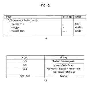
[0031] FIG. 5 (a) is a diagram of a syntax structure of a
2D_3D_transition_info_data_byte according to one embodiment of the present
invention;
[0032] FIG. 5 (b) is a diagram of an interpretation for a
value of a data_type
field according to one embodiment of the present invention;
[0033] FIG. 6 is a diagram of a method of transporting a
2D_3D_transition_info_data_byte according to one embodiment of the present
invention in an MPEG-2 video;
CA 02829112 2013-09-04
[0034] FIG. 7 is a diagram of a method of transporting a
2D_3D_transition_info_data_byte according to one embodiment of the present
invention in an AVC/H.264 video;
[0035] FIG. 8 is a diagram of a structure of a receiver for receiving and
outputting a 3D stereoscopic broadcasting in a dual stream case according to
one
embodiment of the present invention;
[0036] FIG. 9 is a flowchart of a method of receiving a broadcasting
signal
according to a screen conversion between 2D and 3D according to one embodiment
of
the present invention;
[0037] FIG. 10 is a diagram of a basic structure of a 3D image signal
receiver
having an MVC decoder according to one embodiment of the present invention;
[0038] FIG. 11 is a diagram of a basic structure of an L/R splitter
according to
one embodiment of the present invention;
[0039] FIG. 12 is a diagram of a method of supporting 2 types of full
resolution 3D image signals (HD stereo mode) based on an MVC codec according
to
one embodiment of the present invention;
[0040] FIG. 13 is a diagram of a syntax structure to signal in a video
level
according to one embodiment of the present invention;
[0041] FIG. 14 is a diagram of a syntax structure of a
stereo_3D_info_data()
according to one embodiment of the present invention;
[0042] FIG. 15 is a diagram of a method of signaling a 3D service mode by
configuring an SEI message according to one embodiment of the present
invention;
[0043] FIG. 16 is a diagram of a definition for a stream_content and a
component_type according to one embodiment of the present invention;
[0044] FIG. 17 is a diagram of a kind of a service type according to one
embodiment of the present invention;
[0045] FIG. 18 is a syntax structure of a transport_packet() according to
one
embodiment of the present invention;
[0046] FIG. 19 is a syntax structure of an adaptation_field() according
to one
embodiment of the present invention;
[0047] FIG. 20 is a diagram of a structure of a receiver to receive and
output a
6
CA 02829112 2013-09-04
3D stereoscopic broadcasting according to one embodiment of the present
invention;
[0048] FIG. 21 is a diagram of a structure of a transmitter for a frame-
compatible compatible 3DTV service according to one embodiment of the present
invention;
[0049] FIG. 22 is a flowchart of a method of receiving a broadcasting
signal
according to a 3D mode for a full resolution according to one embodiment of
the
present invention.
BEST MODE
[0050] Reference will now be made in detail to the preferred embodiments
of
the present invention, examples of which are illustrated in the accompanying
drawings.
Yet, the present invention may be non-limited or non-restricted by the
embodiments.
[0051] Although terminologies used in the present specification are
selected
from general terminologies used currently and widely in consideration of
functions,
they may be changed in accordance with intentions of technicians engaged in
the
corresponding fields, customs, advents of new technologies and the like.
Occasionally,
some terminologies may be arbitrarily selected by the applicant(s). In this
case, the
meanings of the arbitrarily selected terminologies shall be described in the
corresponding part of the detailed description of the specification.
Therefore,
terminologies used in the present specification need to be construed based on
the
substantial meanings of the corresponding terminologies and the overall
matters
disclosed in the present specification rather than construed as simple names
of the
terminologies.
[0052] The method of expression for a 3 dimensional image may include a
stereoscopic technique considering two viewpoints and a multiple view image
technique
(or a multi-view technique) considering more than 3 viewpoints. Comparably, a
conventional single view image technique may be called a monoscopic image
technique.
[0053] The stereoscopic technique uses a pair of image, i.e., a left view
image
(hereinafter a left image) and a right view image (hereinafter a right image)
obtained by
photographing a same subject with a left camera and a right camera, which are
away a
certain distance from each other. Or, the stereoscopic technique uses a pair
of image of a
7
CA 02829112 2013-09-04
base view video stream and an additional view video stream. The multi-view
technique
uses more than 3 images obtained by photographing with 3 or more cameras
having a
certain distance and angle. In the following description, although the present
invention
explains the stereoscopic technique as one embodiment, the idea of the present
invention may also be applied to the multi-view technique.
[0054] According to the present invention, the stereoscopic technique
includes
a side-by-side, a top-down, a checker board technique, and the like. The side-
by-side
technique is a technique configuring one stereoscopic image by performing a
half down
sampling horizontally on each of a left image and a right image, respectively
and
situating one sampled image in a left region and the other sampled image in a
right
region. The top-down technique is a technique configuring one stereoscopic
image by
performing a half down sampling vertically on each of a left image and a right
image,
respectively and situating one sampled image in a top region and the other
sampled
image in a bottom region. The checker board technique is a technique
configuring one
image by performing a half down sampling in a manner that a left image and a
right
image respectively intersect horizontally and vertically.
[0055] Yet, the stereoscopic technique according to the present invention
may
be non-limited or non-restricted by the aforementioned example. As one
example, it is
also possible to provide a 3D image service in a manner of transceiving two
images
having an intact resolution without going through the aforementioned down
sampling
process. Transceiving two images having an intact resolution can be called a
full
resolution 3D image service. The full resolution 3D image service can be
transmitted to
a user in two ways. For clarity of terminology, a receiver mode for providing
the full
resolution 3D image service is briefly explained.
[0056] First of all, a frame-compatible compatible mode is a method of
transceiving two 3D images, which went through the aforementioned down
sampling, of
a stereoscopic scheme. A receiver represents both a left image and a right
image with a
full resolution in a manner of combining two images down sampled by half and
provides the images as a full resolution 3D image using a binocular parallax.
[0057] A 2D service compatible mode means to transmit a left image of
full
resolution and a right image of full resolution, respectively. A receiver
receives the
8
CA 02829112 2013-09-04
above mentioned left image and the right image and may be able to represent as
a full
resolution 3D image using the binocular parallax. Detail explanation is
described
together with a signaling signal for conversion between modes in the following
description.
[0058]
[0059] First of all, as a 1st embodiment of the present invention, in
case that a
received signal is converted between a 2D image and a 3D image, a preparation
work
for a decoder operation and a method of signaling a timing point of the
decoder
operation to smoothly perform the operation are explained.
[0060] In case that a 2D/3D conversion occurs in a stereoscopic 3DTV
system
based on a single or a dual system, if a disagreement between the 2D/3D
conversion by
an actual frame unit and a signaling data or a synchronization error occurs,
there may
exist a problem as follows.
[0061] In a section converting from a 3D mode to a 2D mode, a) a receiver
may perform a 2D operation even though an actual program corresponds to 3D,
since a
received signaling data judged the program as 2D, b) the receiver may perform
a 3D
operation even though an actual program corresponds to 2D, since a received
signaling
data judged the program as 3D.
[0062] In a section converting from a 2D mode to a 3D mode, c) the
receiver
may perform a 3D operation even though an actual program corresponds to 2D,
since a
received signaling data gives information of 3D, d) the receiver may perform a
2D
operation even though an actual program corresponds to 3D, since a received
signaling
data gives information of 2D. Hence, a method capable of precisely signaling
the 2D/3D
conversion by a frame unit is required.
[0063] In the following description, a method of signaling the 2D/3D
conversion in a stereoscopic 3DTV system based on a dual codec is described.
The
method may include 1) a method of signaling 2D/3D conversion information in an
MPEG-2 transport packet level, 2) a method of signaling the 2D/3D conversion
information in a video level. This method can be identically applied to a
stereoscopic
3DTV system based on a single codec as well.
[0064]
9
CA 02829112 2013-09-04
[0065] FIG. 1 is a diagram of an embodiment for a method of configuring a
stereoscopic 3DTV service based on a dual codec according to a conventional
invention.
100661 The stereoscopic 3DTV service based on a dual codec includes two
videos. A video 1 corresponds to a base view video stream and is used as one
of
stereoscopic viewpoints in the 3DTV service. The video 1 can be used as a 2D
image in
a legacy TV service. A video 2 corresponds to an additional view video stream
and is
used as an enhancement of the video 1 to provide the stereoscopic 3DTV
service.
[0067] A 3D image program includes both the video 1 and the video 2. In
case
that the 3D image program is based on a single codec, the video 1 and the
video 2 can
be encoded using an identical codec. In case that the 3D image program is
based on a
dual codec, the video 1 and the video 2 can be transmitted in a manner of
being
compressed by an individual method, respectively.
[0068]
[0069] FIG. 2 is a conceptual diagram for a conversion between 2D and 3D
in
a stereoscopic 3DTV system based on a dual stream according to one embodiment
of
the present invention.
[0070] Referring to FIG. 2, when a 3D broadcasting is started, the video
1 and
the video 2 are received together. Hence, a decoder for the video 2 should
start to
operate on the exact time according to the start time of the 3D broadcasting.
In case of
converting to a 2D broadcasting again after ending of the 3D broadcasting,
since the
video 1 is received only, the decoder for the video 2 has to stop operating in
time. The
bottom part of the diagram distinguishes cases related to between a receiving
timing
point of the 2D or 3D broadcasting program and an actual operating timing
point of the
decoder according to time.
[0071] In case that a receiving program is converted to 2D, a case A
corresponds to a case that a conversion timing point indicated by a signaling
data is
earlier than the timing point of an actual conversion. In particular, a
receiver outputs a
last part of a 3D program in a 2D mode in the timing point that the actual 3D
program is
not over yet. Although this part is not an intended operation, if it is
considered for an
outputted image only, since a normal image is outputted in the 2D mode even
though it
is not a 3D image, the case A can be regarded as a relatively less critical
case.
CA 02829112 2013-09-04
=
[0072] In case that a receiving program is converted to 2D,
a case B
corresponds to a case that a conversion timing point indicated by a signaling
data is later
than the timing point of an actual conversion. In this case, the decoder for
the video 2 is
off belatedly. A malfunction may occur in a section that the decoder is
incorrectly on. In
particular, although an actually received signal corresponds to a 2D signal, a
receiver
considers the signal as a 3D signal and may be then able to perform a wrong
operation
in a signal processing process. For instance, a static image of a lastly
received 3D image
is maintained as an additional view video stream screen (underflow) and a 2D
dedicated
image, which is currently receiving, is displayed as a base view video stream.
Hence, a
situation that a 3D screen of an abnormal combination is outputted may occur.
[0073] In case that a receiving program is converted to 3D,
a case C
corresponds to a case that a conversion timing point indicated by a signaling
signal is
earlier than the timing point of an actual conversion. In this case, if a
decoder starts to
operate in advance, a malfunction may occur in a section that the decoder is
incorrectly
on. In particular, like as mentioned in the case of malfunctioning on 2D
conversion,
although an actually received signal corresponds to a 2D signal, a receiver
considers the
signal as a 3D signal and may be then able to perform a wrong operation in a
signal
processing process. For instance, a phenomenon that a decoder runs idle
(underflow)
without an additional view video stream may occur. In this case, 3D may
operate under
a situation that an additional view video stream is displayed with a black
color screen
only.
[0074] In case that a receiving program is converted to 3D,
a case D
corresponds to a case that a conversion timing point indicated by a signaling
data is later
than the timing point of an actual conversion. This corresponds to a case that
a 2D mode
is temporarily maintained although an actual 3D program is started. Similar to
the case
A, although this part is not an intended operation, if it is considered in
terms of a display,
since a normal 2D image is outputted, the case D can be regarded as a
relatively less
critical problem.
[0075]
[0076] As a first method to solve the aforementioned
problem, it is able to
safely convert a mode between 2D and 3D in a manner of avoiding a critical
error via a
CA 02829112 2013-09-04
receiver implementation while a legacy signaling scheme is maintained and
controlling
a timing point of conversion.
[0077] In order to perform a 2D/3D conversion on an exact timing point,
it is a
principle that the 2D/3D conversion is performed as frame accurate as
possible. Yet,
under a situation that a signaling scheme for the principle does not exist, it
is hardly
expected that an exact conversion is performed. Hence, as the second best
plan, in case
of converting from 2D to 3D, a conversion is performed in a manner of delaying
(embodiment: about 1 ¨ 2 seconds) the conversion as much as a pre-configured
time
compared to the timing point identified by an actual signaling data to avoid a
critical
error. By doing so, a critical error case corresponding to the case C can be
avoided.
[0078] In case of converting from 2D to 3D, although a signaling
information
on an additional video is included via an SI level signaling, a mode
conversion is not
performed immediately. When a PID stream corresponding to the additional video
is
detected, a conversion to the 3D is performed. In particular, if a PID
corresponding to
the additional video (e.g., AVC/H.264 video) is detected in a demux, the
conversion to
the 3D is performed.
[0079] In case of converting from 3D to 2D, a conversion is performed
earlier
(embodiment: about 1 ¨ 2 seconds) than a timing point of conversion identified
by an
actual signaling data to avoid a critical error. By doing so, a critical error
case
corresponding to the case B can be avoided.
[0080]
[0081] As a second method, there exists a 2D/3D conversion signaling
method
using an adaptation layer of a transport packet.
[0082] FIG. 3 is a diagram of a syntax structure of an MPEG-2 transport
packet according to one embodiment of the present invention. In this case, a
transport
packet level signaling method is able to signal a 2D/3D conversion signal
using an
adaptation_field of a transport packet.
[0083]
[0084] FIG. 4 is a diagram of a syntax structure of an adaptation_field
of an
MPEG-2 transport packet according to one embodiment of the present invention.
A
transport_private_data_flag of the adaptation_field() is set to '1' for
synchronization. By
12
CA 02829112 2013-09-04
using a transport_private_data_length, it is signaled that how many bytes are
in a
private_data_byte. Since a bit number of a signaled conversion signal in an
embodiment
of the present invention corresponds to '40', the
transport_private_data_length has a
value of '5'. It is because the private_data_byte having a size of 8-bit is
able to
represent a conversion signal of 40-bit in a manner of repeating 5 times,
which
corresponds to the value of the transport_private_data_length. The
private_data_byte
includes a 2D_3D_transition_info_data_byte to be explained in FIG. 5 and a
receiver
identifies information on a timing point of conversion by analyzing the
2D_3D_transition_info_data_byte. By doing so, the receiver controls an output
of a
video decoder for an additional view video stream and a related display
module.
[0085]
[0086] FIG. 5 (a) is a diagram of a syntax structure of a
2D_3D_transition_info_data_byte according to one embodiment of the present
invention.
[0087] The 2D_3D_transition_info_data_byte can be positioned at the
private_data_byte part in the adaptation field region of the MPEG-2 transport
packet
and includes information for indicating a timing point of conversion between
2D and
3D. A transition type may be able to indicate whether a conversion of a
received
broadcasting signal is to 2D or to 3D. If the transition type field is set to
'0', it means
the conversion from 2D to 3D. If the transition_type field is set to '1', it
means the
conversion from 3D to 2D. A data_type may be able to indicate a unit of a
transition_count. A detail meaning of the data_type is shown in FIG. 5 (b).
The
transition_count means a timing point that an actual conversion is taking
place.
[0088] FIG. 5 (b) is a diagram of an interpretation for a value of a
data_type
field according to one embodiment of the present invention. For instance, in
case of the
data_type = '0 * 00', a 2D (or a 3D) transition occurs after the packets as
many as the
number specified by a value of the transition_count. The packet including the
2D_3D_transition_info_data_byte is not included in a process of counting a
remaining
time. Moreover, the packet having an identical PID value with a corresponding
packet is
counted only.
[0089] In case of the data_type = '0 * 01', it means that a transition
occurs
13
CA 02829112 2013-09-04
. .
after a picture frame as many as the number specified by the value of the
transition_count.
[0090] In case of the data_type = '0 * 02', the
transition_count clearly informs
a PTS value corresponding to a timing point that an actual transition occurs.
In this case,
a PCR value to be used is on the basis of a recently received PCR. In case
that the PCR
is updated, the PCR value should be transmitted again according to the need.
[0091]
[0092] As a third method, it is able to use a method of
signaling 2D/3D
conversion information in a video level.
[0093] FIG. 6 is a diagram of a method of transporting a
2D_3D_transition_info_data_byte according to one embodiment of the present
invention in an MPEG-2 video.
[0094] The 2D_3D_transition_info_data_byte may be able to
signal a timing
point of conversion in a base view video stream. A receiver refers to a user
structure()
included in the user data() of the base view video stream of the MPEG-2 video.
In this
case, a user_data_start_code corresponds to '0 * 0000 01B2' and a
user_data_identifier
refers to an ATSC_user_data() having a value of '0 * 4741 3934'. Lastly, it is
able to
obtain information on the timing point of conversion from the
2D_3D_transition_info_data_byte having a value of 'a user_data_type_code = '0
* 11'
in the user_data_type_structure().
[0095] In case that the MPEG-2 video corresponds to an
additional view video
stream, information on a conversion from 3D to 2D can be signaled via the
2D _ 3D_ transition info data.
[0096] The 2D_3D transition_info_data is transmitted in a
manner of being
included in the user data() of the Picture Extension and User Data region. The
receiver
extracts the user_data() satisfying a condition that the user_data_start_code
value
corresponds to '0 * 0000 01B2' and the user_data_identifier value corresponds
to '0 *
4741 3934'. The receiver extracts data satisfying a condition that the
user_data_type_code corresponds to '0 * 11' in a manner of reading the data of
the
user _structure(). The receiver recognizes a type and a timing point of
conversion
between 2D and 3D via the 2D_3D_transition_info_data().
14
CA 02829112 2013-09-04
[0097]
[0098] FIG. 7 is a diagram of a method of transporting a
2D_3D_transition_info_data_byte according to one embodiment of the present
invention in an AVC/H.264 video.
[0099] The 2D_3D_transition_info_data_byte may be able to signal a timing
point of conversion in an additional view video stream. In case of H.264 (or
AVC) video,
the 2D_3D_transition_info_data_byte transmits a corresponding information to
SEI
(supplemental enhancement information) region and transmits to make an
user_data_registered_itu_t_1350 include the user_identifier and the
user_structure. In
particular, the 2D 3D transition_info_data_byte transports the corresponding
information to SEI payloads instead of the user_data(). The SEI plays a role
of the
picture extension and user data of the MPEG-2 and can be constrained to have a
similar
position as well.
[00100] In case that the AVC video corresponds to an additional view video
stream, information on a conversion from 3D to 2D can be signaled via the
2D_3D transition info data.
_ _ _
[00101] The 2D_3D_transition_info_data 0 is received via an SEI RBSP (raw
byte sequence payload). If a nal_unit_type value corresponds to '6' by parsing
an AVC
NAL unit, it corresponds to a SEI data. The receiver checks a user_identifier
value by
reading a user_data_registered_itu_t_t35 SEI message satisfying a condition
that a
payloadType corresponds to '4'. The receiver extracts data satisfying a
condition that
the user_data_type_code corresponds to '0 * 11' in a manner of reading the
user_structure() corresponding to a condition that the user_identifier value
corresponds
to '0 * 4741 3934'. The receiver may be able to recognize a timing point of
conversion
from 3D to 2D in a manner of parsing the 2D_3D_transition_info_data().
[00102]
[00103] FIG. 8 is a diagram of a structure of a receiver for receiving and
outputting a 3D stereoscopic broadcasting in a dual stream case according to
one
embodiment of the present invention.
[00104] The receiver may include a tuner 1, a demodulator 2, a TP demux 3,
an
SI processor 4, video decoder 1 and 2 5a/5b, picture engine 6a/6b, an L/R
synchronizer
CA 02829112 2013-09-04
,
7, and an output formatter 8. In this case, the TP demux 3, the SI processor
4, and the
video decoder 1 and 2 5a/5b can be implemented by a single module and the
single
module can be called a decoding module.
[00105] The receiver receives and demodulates a broadcasting signal via
the
tuner 1 and the demodulator 2. The demodulated broadcasting signal is
demultiplexed
by the demux 3. In case of transceiving information on a timing point of
conversion in a
manner of being included in the transport packet of the aforementioned second
method,
the information on a timing point of conversion is extracted by the TP demux 3
and is
then delivered to the SI processor 4 to be processed. The receiver determines
whether
the video 2 is decoded and whether the video 2 is image processed using the
information on a timing point of conversion and may be then able to determine
whether
the video decoder 2 5b and the picture engine 6b operate.
[00106] The demultiplexed video 1 and video 2 are inputted to the video
decoder 1 5a and the video decoder 2 5b, respectively and then decoded. In
case of
transceiving information on a timing point of conversion in a manner of being
included
in the MPEG-2 or the AVC/H.264 video of the aforementioned third method, the
information on a timing point of conversion is extracted when a decoding is
performed
in the video decoder. In this case, the receiver determines whether the video
2 is
decoded and whether the video 2 is image processed using the information on a
timing
point of conversion and may be then able to determine whether the video
decoder 2 5b
and the picture engine 6b operate.
[00107] Each of the decoded video 1 and 2 is inputted to the L/R
synchronizer 7
after going through the picture engine 6a/6b, respectively and then
synchronizes a left
image and a right image. The synchronized left and right image are inputted to
the
output formatter 8 and then provided to a user as a 3D image.
[00108] FIG. 9 is a flowchart of a method of receiving a broadcasting
signal
according to a screen conversion between 2D and 3D according to one embodiment
of
the present invention.
[00109] The receiver receives a digital broadcasting signal including a
video
stream and a signaling data [S10]. The receiver obtains an adaptation_field0
in a
transport packet level or a signaling information on a conversion between 2D
and 3D in
16
,
CA 02829112 2013-09-04
,
. .
a video level [S12]. In this case, the acquisition of the signaling
information in the video
level is achieved from the user_data_type_structure0 in case of the MPEG video
and is
achieved from the SEI region in case of the AVC/H.264 video.
[00110] According to the obtained information on the
conversion between 2D
and 3D, the receiver controls the operation of the video decoder 1 and 2
[S14]. In case
of a conversion from 2D to 3D, the receiver makes both the video decoder 1 and
2
operate. In case of a conversion from 3D to 2D, the receiver temporarily stops
the
operation of the video decoder 2.
[00111] The receiver outputs an image signal outputted from
the video decoder
[S16] and then provides the image signal to a user.
[00112]
[00113] In the following description, a 2nd embodiment of
the present invention
is described. In case that a broadcasting signal supporting a full resolution
is received, a
method of signaling whether a corresponding broadcasting signal corresponds to
a
frame-compatible compatible signal or a 2D service compatible signal and
apparatus
therefor making an UR splitter of a receiver suitably operate according to a
various
types of signal is explained. The 2nd embodiment of the present invention
proposes a
method for a 3DTV based on a multi-layer codec to deal with two types of
stereo 3D
broadcasting modes different from each other. In particular, the 2nd
embodiment of the
present invention proposes an appropriate signaling method and a method of
controlling
a 3D display output based on a corresponding signaling.
[00114] FIG. 10 is a diagram of a basic structure of a 3D
image signal receiver
having an MVC decoder according to one embodiment of the present invention.
[00115] A basic structure from a 3D video decoder module 10
to a 3D formatter
18 of a receiver supporting a stereo 3D broadcasting is shown in FIG. 10. The
video
streams outputted from the multi-layer video decoder 10 are divided into a
left image
and a right image via the L/R splitter module 14. For clarity, an MVC decoder
is
explained as an example in the present embodiment.
[00116] The MVC decoder decodes a base view video stream
with an AVC
decoder 11, performs an inter-layer prediction 12 based on the result of the
decoding
and then inputs to an enhancement decoder 13. The enhancement decoder 13
decodes an
17
CA 02829112 2013-09-04
additional view video stream in a manner of combining the result of the inter-
layer
prediction 12 and an inputted additional view video stream data. An image
decoded in
the AVC decoder 11 and the enhancement decoder 13 is inputted to the L/R
splitter 14
and is then divided into a left image and a right image. Each of the divided
left image
and the right image is provided to a user as a 3D image via the 3D formatter
18 after
going through a deinterlacer 16a/16b and a frame rate controller (FRC)
17a/17b,
respectively. In this case, an SI processor 15 delivers signaling information
to the 3D
video decoder module 10 and the L/R splitter 14 and may be able to make the
decoder
and the splitter suitably operate according to a type of a 3D broadcasting
service.
[00117] A legacy receiver may be able to perform an operation limited to
either
a (2D) service-compatible 3D broadcasting service or a frame-compatible
compatible
(FCC) 3D broadcasting service. The present invention includes a scenario
realizing a
3D output and a 2D output for all cases. To this end, a new receiver operation
mechanism in the L/R splitter 14 and a signaling in a system layer via an SI
are required.
[00118]
[00119] FIG. 11 is a diagram of a basic structure of an L/R splitter
according to
one embodiment of the present invention.
[00120] A base stream 20 and an enhancement stream 21 corresponding to the
input value of the L/R splitter module 23 are differently processed according
to a stereo
broadcasting mode.
[00121] In case of a frame-compatible compatible 3D broadcasting, the
video
stream 20 transmitted to a base layer corresponds to an image of a frame-
compatible 3D
form. The video stream 21 transmitted to an enhancement layer may also
correspond to
an image of the frame-compatible 3D form or may correspond to a data of a
different
form in some cases.
[00122] In case of a service-compatible compatible 3D broadcasting, the
video
stream 20 transmitted to the base layer corresponds to an image of a 2D form
compatible with a legacy full HD 2D broadcasting. The video stream 21
transmitted to
the enhancement layer may also correspond to an image of the 2D form or may
correspond to a data of a different form such as a depth map in some cases.
[00123] The L/R splitter 23 combines two video streams 20/21 to coincide
with
18
CA 02829112 2013-09-04
a type of a 3D broadcasting delivered from the SI processor 15 or an SEI
messages 22
and may be able to output a right image 25 and a left image 25 of full
resolution with
the result of the combination.
[00124] A method of combining a stream varies according to each mode and
the
method is described in the following description.
[00125]
[00126] FIG. 12 is a diagram of a method of supporting 2 types of full
resolution 3D image signals (HD stereo mode) based on an MVC codec according
to
one embodiment of the present invention.
[00127] FIG. 12 (a) is a diagram of operation of the L/R splitter 23 in
case that a
received signal corresponds to a frame-compatible compatible mode.
[00128] A frame-compatible compatible mode service is a structure
compatible
with a conventional frame-compatible (phase 1) service. An image signal
consists of a
base layer (Lb/Rb) 31 corresponding to a phase 1 3DTV and an enhancement layer
(Le/Re) 32. First of all, a video signal (Lb/Rb) received via the base layer
is divided into
a left and right image of a half resolution via a local splitter in the L/R
splitter 23 after a
decoding is performed. And, a video signal (Le/Re) received via the
enhancement layer
is also divided into a left and right image of a half resolution via a local
splitter in the
L/R splitter 23 after a decoding is performed. The video signal split after
the decoding
generates a full resolution image in a manner of being merged by an identical
eye-view
unit.
[00129] In particular, a full resolution left image (LO 34 is generated by
combining the Lb with the Le and a full resolution right image (RO 33 is
generated by
combining the Rb with the Re. Consequently, this full resolution image pair
(the Lf and
the RI) is went through the 3D formatter and is then finally outputted via a
3D display.
[00130] FIG. 12 (b) is a diagram of operation of the L/R splitter 23 in
case that a
received signal corresponds to a 2D compatible mode.
[00131] A 2D compatible mode service is a structure compatible with a
conventional 2D HD service. An image signal consists of a base layer
corresponding to
an HD service (2D) and an enhancement layer. In this case, one eye-view among
the left
and the right is selected and transmitted via the base layer and the remaining
eye-view is
19
CA 02829112 2013-09-04
,
. .
transmitted via the enhancement layer. According to the present embodiment,
the left
image (Lb) 35 is transmitted via the base layer and the right image (Re) 36 is
transmitted via the enhancement layer. It is possible to transmit the right
image (Rb) via
the base layer and transmit the left image (Le) via the enhancement layer
according to
embodiment.
[00132] The received base and enhancement layer are
outputted to
corresponding view positions after going through switching (blocks represented
by 1
and 2) according to eye-views, which correspond to the base and enhancement
layer,
respectively. In particular, according to whether the base layer is left or
right, it is
determined whether a matching is heading to the Lf 34 or the Rf 33. The
reconstructed
full resolution videos (the Lf and the RD are finally outputted via the 3D
display after
going through the 3d formatter, respectively.
[00133] A full resolution 3D broadcasting can be outputted
by combining the
stream received via the base layer with the stream received via the
enhancement layer in
case of both the frame-compatible compatible mode and the 2D compatible mode.
Although a received stream is different, an output, which corresponds to a
full HD left
image and a full HD right image, outputted from the L/R splitter module is
identical.
Hence, if a single L/R splitter module supports all of the processing methods
of FIG. 12
(a) and (b), a receiver may be able to provide a full resolution 3D
broadcasting no
matter what mode is received by the receiver. In the following description, a
method of
signaling which mode is used to transceive a full resolution 3D broadcasting
signal is
explained.
[00134]
[00135] A major part of a signaling is to indicate that
which 3D mode is used. A
needed information for outputting per each mode is as follows.
[00136] In case of the frame-compatible compatible mode, a
format type of a
broadcasting signal should be signaled. For instance, the format type may
correspond to
a side by side type, a top and bottom type, a checkerboard type, or the like.
A position of
a left and right image and sampling mode (even, odd) information should be
signaled
together.
[00137] In case of the 2D service compatible mode, the
position information of
CA 02829112 2013-09-04
=
the left and the right image indicating whether a base layer stream
corresponds to a left
image or whether an enhancement layer stream corresponds to the left image
should be
signaled.
[00138] Mode information and detail information per each
mode can be
delivered via a signaling in a video level, the signaling in a system level,
or the
signaling in a transport packet level.
[00139] In case of signaling a 3D mode in the video level,
two methods, i.e.,
expansion of a legacy SEI message or designation of a new SEI message can be
used.
[00140] In case of signaling the 3D mode in the system
level, a component type,
a new descriptor, or a service type can be used.
[00141] In case of signaling the 3D mode in the transport
packet level, count
information and/or 3D mode information in the method of using an adaptation
layer can
be used.
[00142] In terms of using the aforementioned three methods,
if a conversion
between 3D modes occurs in the middle of watching, it is difficult to
precisely handle a
timing point of conversion with the signaling in the system level only. Thus,
it is
necessary to inform the conversion information between 3D modes by the video
level.
Hence, a method of signaling by the transport packet level or the video level
is
necessary. In particular, the signaling of the system level should be
accompanied by the
signaling of the video level or the transport packet level.
[00143]
[00144] FIG. 13 is a diagram of a syntax structure to signal
in a video level
according to one embodiment of the present invention.
[00145] In case of an H.264 (or AVC) video, it is able to
signal by utilizing an
SEI (supplemental enhancement information) region.
[00146] FIG. 13 (a) is a diagram of an SEI syntax structure
to transmit a
stereo_3D_info_data() according to one embodiment of the present invention. It
is
transmitted to include a user_identifier and a user_structure in a
user_data_registered_itu_t_1350. A video stream in which an information is
included
may correspond to both a base layer and an enhancement layer. A signaling can
be
performed by two methods, i.e., expanding a conventional SEI message and
designating
21
CA 02829112 2013-09-04
a new SE! message.
[00147] First of all, a method of expanding a conventional SEI message can
be
used by expanding a syntax structure depicted in FIG. 13 to send an auxiliary
data to a
video elementary stream. In an SEI syntax in FIG. 13 (a), the user_identifier
and the
user_structure use '0 * 4741 3934 ('GA94') and a DVB1_data() value as shown in
FIG.
13 (b). In this case, as shown in FIG. 13 (c), a user_data_type_code and a
user_data_type_structure() in the DVB1_data are used by assigning an expanded
value
to transmit 3D stereo related information to the user_data_type_code and the
user_data_type_structure(). In this case, values to be assigned are shown in
FIG. 13 (d).
The value of the user_data_type_code according to one embodiment of the
present
invention corresponds to '0 * 04' and the content of the
user_data_type_structure() may
correspond to `stereo_3D-info_data(l.
[00148] FIG. 14 is a diagram of a syntax structure of a stereo_3D
info_data()
according to one embodiment of the present invention.
[00149] A stereo_3D field is a field indicating that a current stream
belongs to
which type of stereo 3D service. An available 3D mode may include a frame-
compatible
compatible 3D service, a 2D service compatible 3D service, and the like.
[00150] An LR_first field is a field indicating whether a pixel situating
at the
very left in a screen configuring a frame-compatible 3D service for a current
layer (or a
stream) is left or a right.
[00151] A stereoformat field is a field indicating a type of a
stereoformat of a
current layer (or a stream). The type of the stereo format may include a side-
by-side, a
top-and- bottom, a checkerboard, and the like.
[00152] A left_view_sampling_mode field means a left image sampling mode
for a current layer (or a stream). In case that the stereoformat corresponds
to the side-
by-side, this field indicates whether a sampling of a vertical direction
extracted an even
line or an odd line. In case that the stereo_format corresponds to the top-and-
bottom,
this field indicates whether a sampling of a horizontal direction extracted an
even line or
an odd line. In case of the checkerboard format, this field also indicates
that which
mode is used among the two available methods.
[00153] A right_view_sampling mode means a right image sampling mode for a
22
CA 02829112 2013-09-04
current layer (or a stream). Details are identical to the
left_view_sampling_mode field.
[00154] An LR flag field is a field indicating whether a stream
corresponding
to a base layer among the streams configuring a 2D service compatible 3D
service is left
or a right. This can be signaled in a way of indicating whether a stream to
which a
corresponding data is delivered is left or a right.
[00155] In the following description, a method of configuring a new SEI
message is explained. This corresponds to a case that a new SEI message is
individually
defined to indicate a 3D service mode without using the aforementioned
user_data_registered_itu_t_l 350. This method uses a following method.
[00156] FIG. 15 is a diagram of a method of signaling a 3D service mode by
configuring an SEI message according to one embodiment of the present
invention.
[00157] An sei_message in FIG. 15 (a) includes a payloadType field. The
payloadType field may be able to define a type of each sei_payload. Hence, in
case that
a payloadType corresponds to a value of '36' in the sei_payload syntax
structure in FIG.
15 (b), a 3D service mode can be signaled using a stereo_3D info in FIG. 15
(c).
[00158] The stereo_3D_info includes the stereo_3D_mode, the LR_first, the
stereo format, the lekview_sampling_mode, a right_view_sampling_mode, and the
LR_flag field. Explanation on each field is already explained in the above
description.
[00159]
[00160] In case of signaling a 3D mode in a system level, it may be able
to use
a component type of a DVB SI, a 3D stereo descriptor, or a service type.
[00161] Since a signaling using the component type in the system level
informs
a type of each stream via a value of a stream_content and a component_type, it
is able
to judge a 3D mode to which a broadcasting signal belongs thereto and an L/R
configuration method in a manner of checking a component value of a stream.
[00162] FIG. 16 is a diagram of a definition for a stream_content and a
component_type according to one embodiment of the present invention. When a 3D
mode is signaled in a system level, a stream_content is set to '0 * 05'. A
component_type has a value ranging from '0 * 84 to 0 * 8b'. According to each
of the
values, the mode of a full resolution 3D broadcasting signal is determined. In
case of a
frame-compatible compatible mode, a side-by-side type or a top-and-bottom type
is
23
CA 02829112 2013-09-04
determined. And, in case of a 2D service compatible mode, a left image or a
right image
is determined. A receiver identifies the 3D mode and a 3D screen configuration
according to a component type (the stream_content and the component type). The
identified information is delivered to the L/R splitter and can be used to
extract a left
and a right image of full HD.
[00163] Similar to this, the 3D mode signaling in the system level can be
performed based on an ATSC PSIP in case of an ATSC scheme. It is able to use
TVCT
and EIT of the PSIP. The TVCT uses a method of transmitting fields of the
stereo_3D_info_data using a descriptor of a virtual level. And, the EIT may be
able to
signal a 3D service mode for a future event in a manner of transmitting field
information of the stereo_3D_info_data using a descriptor of an event level.
[00164]
[00165] A method of signaling in a system level using a descriptor can use
a
3D_stereo_info_descriptor. This is situated at the descriptor attached to each
elementary
stream inside of an SDT section of a DVB. In particular, the
3D_stereo_info_descriptor
is situated at a base layer stream or an enhancement layer stream. Details are
already
described in FIG. 14 and may include identical field. A receiver identifies a
3D mode
information and a 3D screen configuration information in a manner of parsing a
stereo_3D_info_descriptor() included in the base layer or the enhancement
layer.
[00166] The 3D mode can also be signaled in the system level using a
service_type and a service configuration may have two types as follows. There
may
exist a case that a stream delivered via the base layer and a stream delivered
via the
enhancement layer belong to an identical service or a case that the stream
delivered via
the base layer and the stream delivered via the enhancement layer belong to a
service
different from each other.
[00167] FIG. 17 is a diagram of a kind of a service type according to one
embodiment of the present invention. First of all, in case that a stream
delivered via the
base layer and a stream delivered via the enhancement layer belong to an
identical
service, a service_type of a 2D service compatible 3D service corresponds to
'0 * 22'
and the service_type of a frame compatible 3D service corresponds to '0 * 1F'.
From
this, it is able to signal that it corresponds to a phase 2 (2D service
compatible) 3DTV
24
CA 02829112 2013-09-04
service.
[00168] As a different case, in case that a stream delivered via the base
layer
and a stream delivered via the enhancement layer belong to a service different
from
each other, a service including the stream corresponding to the base layer
corresponds to
'0 * 19' or '0 * IC' and a service including the stream corresponding to the
enhancement layer can be signaled in a manner of designating with such a new
service_type form as '0 * 25' and '0 * 28'. In case of being transmitted to a
service
different from each other, the type of the 3D mode can be identified if one of
the two
services is checked only.
[00169] A receiver identifies the 3D mode information in a manner of
checking
the service_type value via the aforementioned signaling signal. Detail
information can
be identified based on the component type value or the content of the
stereo_3D_info_descriptor() included in the signal after parsing each element.
The
identified information is delivered to the L/R splitter module and can be used
to extract
a left and right image of full HD.
[00170]
[00171] A signaling in a transport packet level can be performed using an
adaptation layer.
[00172] FIG. 18 is a syntax structure of a transport_packet() according to
one
embodiment of the present invention. For a signaling in the transport packet
level, an
adaptation_field() in a transport_packet() can be used. Specifically, it is
able to signal
using a private_data_byte() field in the adaptation_field(). The
adaptation_field() is
described in detail in FIG. 19.
[00173] FIG. 19 is a syntax structure of an adaptation_field() according
to one
embodiment of the present invention. In this case, the private_data_byte
included in the
adaptation_field() contains an identical content with the
stereo_3D_info_data()
suggested in the aforementioned video level signaling.
[00174] In the adaptation_field(), a transport_private_data_flag indicates
whether the private_data_byte exists. A transport_private_data_length signals
a byte
number of the private_data_byte and the private_data_byte includes the content
of the
stereo_3D_info_data().
CA 02829112 2013-09-04
. ,
[00175] Operation sequence of a receiver is as follows. The
receiver checks that
the transport_private_data_flag of the adaptation_field0 corresponds to ' 1 '.
After
checking that the transport_private_data_flag corresponds to ' I ', the
receiver checks the
number of byte of the private_data_byte using the
transport_private_data_length. If the
stereo_3D_info_data() is signaled via the private_data_byte, the receiver
identifies a 3D
mode and the information on a stereo broadcasting configuration by reading the
signaling information. The receiver controls the output of the L/R splitter
module
receiving the base stream and the enhancement stream as an input value using
the
identified information.
[00176]
[00177] As mentioned in the foregoing description, in case
that the receiver
receives a 3D image signal, an operation of the receiver varies according to
each mode.
Moreover, the operation of the receiver may vary according to a 3D mode even
in case
of watching a 2D view.
[00178] In case of a 2D service compatible 3D service, the
receiver may be able
to display a 2D screen in a manner of selecting either the base layer stream
or the
enhancement layer stream. In particular, in this case, it is not necessary to
go through
the L/R splitter module.
[00179] In case of a frame-compatible compatible 3D service,
since each half of
the screen configuring a 2D screen is delivered to the base layer and the
enhancement
layer, respectively, the receiver may be able to display a 2D in a manner of
selecting one
of the L/R images went through the L/R splitter.
[00180]
[00181] FIG. 20 is a diagram of a structure of a receiver to
receive and output a
3D stereoscopic broadcasting according to one embodiment of the present
invention.
[00182] The receiver may include a tuner 40, a demodulator
41, a TP demux 42,
an SI processor 43, an AVC layer decoder 44, an MVC extension layer decoder
45, an
L/R splitter 46, and an output formatter 47. In this case, the TP demux 42,
the SI
processor 43, and the AVC layer decoder / the MVC extension layer decoder
44/45 can
be implemented by a single module and the single module can be called a
decoding
module.
26
CA 02829112 2013-09-04
. ..
[00183] The receiver receives and demodulates a broadcasting
signal via the
tuner 40 and the demodulator 41. The demodulated broadcasting signal is
demultiplexed
by the TP demux 42. In case of transceiving information on a 3D mode in a
manner of
being included in the aforementioned transport packet, the information on a
timing point
of conversion is extracted by the TP demux 42 and is then delivered to the SI
processor
44 to be processed.
[00184] The demultiplexed base layer video and the
enhancement layer video
are inputted to the AVC layer decoder 44 and the MVC extension layer decoder
45,
respectively and then decoded. In case that the 3D mode information is
signaled in a
video level, the receiver may be able to obtain the 3D mode information in
this
decoding process.
[00185] Both the decoded base layer video and the
enhancement layer video are
inputted to the L/R splitter 46 and then merged, switched, or bypassed
according to the
signaled 3D mode, and then outputted as a left image and a right image of full
resolution. The outputted left and right image are inputted to the output
formatter 47 and
then provided to a user as a 3D image.
[00186]
[00187] FIG. 21 is a diagram of a structure of a transmitter
for a frame-
compatible compatible 3DTV service according to one embodiment of the present
invention. The transmitter structure operates according to the steps of
obtaining a left /
right image (image capture 50), dividing the obtained image into a left and a
right and
dividing a layer according to a service mode (layer separation 51), encoding a
video for
each layer (encoding 52), and multiplexing & transmitting (mux & transport
53). In this
case, the present invention explains the layer separation step for full
resolution.
[00188] The transmitter may include a subtractor 54a/54b, a
down-sampling
unit 55a/55b, a residual unit 56a/56b, a mixer 57a/58b, a base layer video
encoder 58,
an inter-layer prediction 59, and an enhancement layer video encoder 60.
[00189] In case of a frame-compatible compatible service
mode, the transmitter
performs a down-sampling 55a/55b for a left and right image to generate a
frame
compatible (side-by-side, top-and-down) video signal. The transmitter goes
through the
subtractor 54a/54b to separate a residual signal of a left/right image of full
resolution
27
CA 02829112 2013-09-04
,
and the down-sampled left/right image. The signal went through the subtractor
54a/54b
is inputted to the residual unit 56a/56b. The residual signal consists of a
remaining
signal except the down-sampled left/right image in the left/right image of
full resolution.
[00190] A result of down-sampling 55a/55b for the left/right image merges
via
the mixer 57b and is then inputted to the base layer video encoder 58 to be
encoded.
And, the output value of the residual unit 56a/56b for the left/right image
merges via the
mixer 57a and is then inputted to the enhancement layer video encoder 60. The
enhancement layer video encoder 60 receives the inter-layer prediction (in
case of using
the MVC codec, inter-view prediction) 59 from the base layer video encoder 58
and
then encodes the enhancement layer on the basis of the base layer.
[00191] In particular, a broadcasting signal transmitter of the frame-
compatible
compatible service may include two down-sampling units configured to perform a
down-sampling for an inputted original left/right image signal, two
subtractors
configured to output a difference between the original left/right image signal
and a
down-sampled left/right image signal, a 1st mixer configured to merge the down-
sampled left/right image signal, a 2" mixer configured to merge the left/right
residual
image signals which correspond to the output of the two subtractors, a 1st
video encoder
configured to encode the output of the 1st mixer to the base layer, and a 2nd
video
encoder configured to encode in a manner of considering the output of the 2nd
mixer and
the result of the inter-layer prediction from the 1st video encoder together.
[00192] And, in case of a 2D service compatible mode, since a left and
right
image are directly inputted to the base layer video encoder 58 or the
enhancement layer
video encoder 60, a structure of the layer separation module is relatively
simple.
[00193]
[00194] FIG. 22 is a flowchart of a method of receiving a broadcasting
signal
according to a 3D mode for a full resolution according to one embodiment of
the
present invention.
[00195] The receiver receives a video stream and a digital broadcasting
signal
including a signaling data [S20]. The receiver obtains an adaptation_field()
in a
transport packet level, SI information in a system level, or a signaling
information on a
3D service mode in a video level [S22]. In this case, obtaining the signaling
information
28
CA 02829112 2015-08-17
74420-654
in the video level can be achieved from a user data_type_structure() in case
of an MPEG
video and can be achieved in an SEI region in case of an AVC/H.264 video.
[00196] The receiver controls the operation of the L/R splitter
according to the obtained
3D service mode [S24]. In case of the frame-compatible compatible service
mode, an inputted
image is separated by a local splitter and outputted by merging according to
each timing point.
In case of the 2D service compatible mode, the inputted image is directly
outputted according
to a left/right image or is outputted by being switched. Detail explanation is
described in
FIG. 12.
[00197] The receiver outputs an image signal outputted from the L/R
splitter [S26] and
then provides to a user.
[00198] The aforementioned signaling information for a conversion
between 2D and
3D mode of the 1st embodiment and the signaling information for the conversion
between the
2D service compatible mode and the frame-compatible compatible mode of the 2"
embodiment can be used in a manner of being transmitted together in a single
system as well
as being transmitted from systems different from each other. The receiver
receives at least one
of the aforementioned two signaling signals and processes the signal. the
receiver may be able
to control the operation of a decoding module according to the corresponding
information.
[00199]
[00200] While the present invention has been described and illustrated
herein with
reference to the preferred embodiments and diagrams thereof, the present
invention may be
non-limited to the embodiments and it will be apparent to those skilled in the
art that various
modifications and variations can be made therein without departing from the
scope of the
invention. Thus, it is intended that the present invention covers the
modifications and
variations of this invention that come within the scope of the appended claims
and their
equivalents. The scope of the claims should not be limited by the examples
herein, but should
be given the broadest interpretation consistent with the description as a
whole.
29
CA 02829112 2015-08-17
74420-654
MODE FOR INVENTION
100201] As mentioned in the foregoing description, the related is
described in the best
mode for invention.
INDUSTRIAL APPLICABILITY
1002021 As mentioned in the foregoing description, the present invention
can be
29a
CA 02829112 2013-09-04
=
applied to a whole or a part of a digital broadcasting system.