Language selection

Search

Patent 2829355 Summary

Third-party information liability

Some of the information on this Web page has been provided by external sources. The Government of Canada is not responsible for the accuracy, reliability or currency of the information supplied by external sources. Users wishing to rely upon this information should consult directly with the source of the information. Content provided by external sources is not subject to official languages, privacy and accessibility requirements.

Claims and Abstract availability

Any discrepancies in the text and image of the Claims and Abstract are due to differing posting times. Text of the Claims and Abstract are posted:

  • At the time the application is open to public inspection;
  • At the time of issue of the patent (grant).
(12) Patent: (11) CA 2829355
(54) English Title: RETRACTABLE SYRINGE WITH SEGMENTED RETAINING LEDGE
(54) French Title: SERINGUE RETRACTABLE AYANT UN REBORD DE RETENTION SEGMENTE
Status: Granted
Bibliographic Data
(51) International Patent Classification (IPC):
  • A61M 5/34 (2006.01)
  • A61M 5/50 (2006.01)
(72) Inventors :
  • CAIZZA, RICHARD (United States of America)
(73) Owners :
  • MIDLAND MEDICAL DEVICES HOLDINGS, LLC (United States of America)
(71) Applicants :
  • MIDLAND MEDICAL DEVICES HOLDINGS, LLC (United States of America)
(74) Agent: GOWLING WLG (CANADA) LLP
(74) Associate agent:
(45) Issued: 2014-02-25
(86) PCT Filing Date: 2012-03-06
(87) Open to Public Inspection: 2012-09-13
Examination requested: 2013-11-07
Availability of licence: N/A
(25) Language of filing: English

Patent Cooperation Treaty (PCT): Yes
(86) PCT Filing Number: PCT/US2012/027924
(87) International Publication Number: WO2012/122191
(85) National Entry: 2013-09-06

(30) Application Priority Data:
Application No. Country/Territory Date
61/449,981 United States of America 2011-03-07

Abstracts

English Abstract

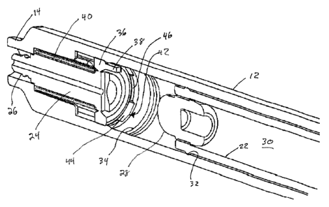
A retractable needle syringe having a segmented retaining ledge at the distal end of the syringe barrel. The retaining ledge has uniformly spaced members configured to enable the retaining ring to break from the needle stem with a reduced plunger engagement force, which provides an improved tactile feeling of the syringe plunger and comfort of use. The segmented retaining ledge also makes it easier to install the needle stem and retaining ring in the barrel distal end, such that it snaps into place therepast with less axial force.


French Abstract

L'invention concerne une seringue à aiguille rétractable ayant un rebord de rétention segmenté à une extrémité distale du corps de seringue. Le rebord de rétention comporte des éléments uniformément espacés conçus pour permettre à l'anneau de rétention de se rompre de la tige de l'aiguille avec une force d'insertion du piston réduite, ce qui confère une meilleure sensation tactile du piston de la seringue et un confort d'utilisation. Le rebord de rétention segmenté facilite également l'installation de la tige de l'aiguille et de l'anneau de rétention dans l'extrémité distale du corps de seringue, de telle sorte qu'il s'encliquette au-delà avec une force axiale moindre.

Claims

Note: Claims are shown in the official language in which they were submitted.


What is claimed is:
1. A syringe, comprising:
a barrel having a proximal end and a distal end, and an interior surface
defining a cavity
configured as a fluid transfer device
a plunger disposed in the barrel and configured to advance toward the barrel
distal and
proximal ends;
a needle stem disposed in the barrel distal end;
a needle assembly selectively coupled to the needle stem and configured to
deliver a fluid
upon advancement of the plunger toward the barrel distal end; and
wherein the barrel interior surface comprises a segmented retaining ledge at
the burel
distal end configured to secure the needle stem distal of the segmented
retaining ledge, wherein
the segmented retaining ledge comprises a plurality of members extending
inwardly from the
barrel interior surface with a space defined between each of the members,
wherein the needle
stem includes a retaining ring disposed annularly thereabout, wherein the
segmented retaining
ledge is configured to reduce an engagement force of the plunger necessary to
separate the
retaining ring from the needle stem.
2. The syringe as specified in claim 1 wherein the segmented retaining
ledge extends
annularly about the barrel cavity.
3. The syringe as specified in claim 1 wherein the members are uniformly
spaced from one
another.
4. The syringe as specified in claim 1 wherein the retaining ring is
configured to be broken
from the needle stem, wherein the segmented retaining ledge is configured to
reduce an
engagement force of the plunger necessary to break the retaining ring from the
needle stem.
5. The syringe as specified in claim 1 wherein the needle stem and the
needle assembly are
configured to automatically retract past the segmented retaining ledge and
within the barrel upon
delivery of the fluid from the barrel.
6. The syringe as specified in claim 5 wherein the needle stem is spring
biased toward the
barrel proximal end.

6

7. A syringe, comprising:
a barrel having a proximal end and a distal end, and an interior surface
defining a cavity
configured as a fluid transfer device a plunger disposed in the barrel and
configured to advance
toward the barrel distal and proximal ends;
a needle stem disposed in the barrel distal end;
a needle assembly selectively coupled to the needle stem and configured to
deliver a fluid
upon advancement of the plunger toward the barrel distal end; and
wherein the barrel interior surface comprises a segmented retaining ledge at
the barrel
distal end configured to secure the needle stem distal of the segmented
retaining ledge, wherein
the segmented retaining ledge comprises a plurality of members extending
inwardly from the
barrel interior surface with a space defined between each of the members,
wherein the needle
stem includes a retaining ring disposed annularly thereabout, wherein the
segmented retaining
ledge is configured to reduce an axial force required to advance the retaining
ring distally
thereover.
8. The syringe as specified in claim 7 wherein the segmented retaining
ledge has rounded
surfaces configured to engage the needle stem as it is advanced distally
thereover during
installation into the barrel distal end.
9. A syringe, comprising:
a barrel having a proximal end and a distal end, and an interior surface
defining a cavity
configured as a fluid transfer device a plunger disposed in the barrel and
configured to advance
toward the barrel distal and proximal ends;
a needle stem disposed in the barrel distal end;
a needle assembly selectively coupled to the needle stem and configured to
deliver a fluid
upon advancement of the plunger toward the barrel distal end; and
wherein the barrel interior surface comprises a segmented retaining ledge at
the barrel
distal end configured to secure the needle stem distal of the segmented
retaining ledge, wherein
the segmented retaining ledge comprises a plurality of members extending
inwardly from the
barrel interior surface with a space defined between each of the members,
wherein the barrel has

7

a space distal of the segmented retaining ledge, wherein the needle stem is
configured to snap
distal of the segmented retaining ledge and seat in the space.

8

Description

Note: Descriptions are shown in the official language in which they were submitted.


CA 02829355 2013-11-07
WO 2012/122191 PCDUS2012/027924
RETRACTABLE SYRINGE WITH SEGMENTED RETAINING LEDGE
[0001]
BACKGROLTND OF THE INVENTION
{0002] The present invention is directed to safety syringes, and particularly
syringes with
retractable needles confirured to retract after use and prevent re-use and
unintended sticking.
Retractable syringes are known in the art, which typically include a needle
configured to
automatically retract into a syringe barrel after delivery of a medicant into
a patient In some
designs, a needle stem including a separable or breakable retaining ring
thereabout is installed
through a barrel proximal end and secured in the barrel distal end. The needle
stem may be
fixedly secured or selectively secured to a needle. Conventional mechanisms
that secure the
needle stem and retaining ring in place define a required axial plunger force
required to
selectively break the needle stem from the retaining ring after final use to
allow automatic
retraction of the spring biased needle.
[0003] There is desired a retractable syringe configured to enable the
retaining ring to break from
the needle stem with a reduced plunger engagement force, which provides an
improved tactile
feeling of the syringe plunger and comfort of use. There is also desired a
retractable syringe
configured to make it easier to install the needle stem and retaining ring in
the barrel distal end,
such that it can snap into place therepast with less axial force.

CA 02829355 2013-09-06
WO 2012/122191 PCT/US2012/027924
BRIEF DESCRIPTION OF THE FIGURES
[0004] Figure 1 shows an exploded view of a retractable syringe having a
conical frustum tip, as
well as an interchangeable needle and hub forming a needle assembly configured
to extend
through the conical frustum tip;
[0005] Figure 2 shows a longitudinal cross sectional view of the syringe of
Figure 1 depicting a
needle stem positioned in the syringe distal end and configured to receive the
interchangeable
needle assembly disposed through the conical frustum tip;
[0006] Figure 3 shows an enlarged sectional view of the syringe distal end
illustrating the needle
stem having a threaded distal end configured to receive needles of various
sizes through the
conical frustum tip;
[0007] Figure 4 shows a longitudinal cross sectional view of the syringe of
Figure 1 depicting the
needle assembly after retraction into the syringe barrel; and
[0008] Figure 5 shows a cross section of the syringe barrel just distal of the
segmented retaining
ledge shown in Figure 3.
2

CA 02829355 2013-11-07
WO 2012/172191 PCUUS2012/027924
SUMMARY OF TIM INVENTION
[0009] The present invention achieves technical advantages as a retractable
needle syringe
having a segmented retaining ledge at the distal end of the syringe barrel
interior wall. The
segmented retaining ledge is defined by a plurality of spaced raised dimples,
notches or detents
in the ledge to provide several features. The segmented retaining ledge
locates the needle stem
and retaining ring in the interior of the barrel and resists movement in the
proximal direction due
to the energized spring while enables the retaining ring to break from the
needle stem with a
reduced plunger engagement force, which provides an improved tactile feeling
of the syringe
plunger and comfort of use. The segmented ledge also makes it easier to
install the needle stem
and retaining ring in the barrel distal end, such that it snaps into place
therepast with less axial
force.
DETAILED DESCRIPTION OF A PREFERRED EMBODIMENT
[0010] Referring to Figure 1 there is shown a retractable needle syringe 10
having a syringe
barrel 12 with a distal end 14 configured as a conical frustum tip. The
conical frustum tip 14 is
configured to attach to female Luer* compatible devices including a filling
needle & Luer hub 16
as shown, collectively referred to as a luer filling needle, as well as
delivery tubes and the like.
The syringe 10 is also shown to include a selectively attachable,
interchangeable needle
assembly 18 including a needle and threaded needle hub, allowing needles of
different sizes and
lengths to be interchanged with the syringe 10. Needle assembly 18 has
radially extending ribs
and is configured to be threadably coupled to a threaded needle stem 24 within
the distal end of
the conical frustum tip 14, as shown in the Figure 2 as will be described
shortly. Syringe 10 also
includes a syringe proximal end 20 and a plunger 22 slidable therein from the
proximal end, the
plunger 22 configured to both aspirate a fluids through the Luer filling
needle/hub 16, and also
dispense the medicant upon compression. The plunger 22 is also configured to
aspirate a fluid
through the needle assembly 18 if desired. The filling needle/hub 16 may be
desired as it is a
common inexpensive needle that can also speed up the drawing process, and also
prevents the
possible unintentional retraction of the needle assembly 18 during insertion
into the medicant
vial or during the handling of the syringe 10 when drawing the medicant
Moreover, the conical
*trade mark 3

= = CA 02829355 2013-11-07
WO 2012/122191
PCT/US2012/027924
frustum tip 14 advantageously allows the syringe 10 to be conveniently
prefilled with medicant
at one place and capped, then transported to a patient with or without needle
assembly 18 as
desired. This design is a significant advantage for many healthcare providers
involved in the
processing and handling of syringes until ultimate delivery of the medicant to
a patient.
[0011] Referring to Figure 2, there is shown a longitudinal cross sectional
view of syringe 10 of
Figure 1, detailing the needle stem 24 having a threaded distal end 26
configured to receive the
needle assembly 18. Notably, the needle stem 24 is positioned within the
distal end of the
conical frustum tip 14 and is advantageously protected from axial forces which
could
inadvertently being contacted and creating an unintended retraction of spring
biased needle stem
24, such as when the needle assembly is secured to needle stem. Also shown is
the plunger 22
having a plug 28 at a distal end thereof, which plug is in sealing arrangement
with a cavity 30 of
plunger 22 prior to retraction of needle assembly 18 therein, and which plug
is dislodged into the
cavity by the needle stem 24 that retracts with needle assembly 18 after an
injection. The distal
end of plunger 22 proximate the plug 28 has an integral seal 32 extending
annularly thereabout.
The interior surface of the syringe includes a plurality of annular detents 34
configured for
positioning the seal 32 in a rested position, before the distal end of plunger
22 axially engages a
protrusion 38 of an annular ring 36 coupled to the needle stem 24 by a
breakable membrane, as
more fully described in Applicant's U.S. Patent 7,803,132 Bl.
[0012] Figure 3 depicts an enlarged cross sectional view of the needle stem
24, including the
threaded needle distal end 26, positioned within the conical frustum tip 14,
and coupled to the
retaining ring 36 with protrusion 38 by the breakable membrane. Also shown is
a spring 40
configured to retract the needle assembly 18 in response to the plunger 22
engaging the
protrusion 38 after delivering the medicant to create a progressive separation
of the retaining ring
36 from the needle stem 24 and the retraction of needle stem 24 into the
plunger cavity 30. The
annular detents 34 configured to seat position seal 32 are also shown.
[0013] This Figure 3 also shows the interior surface of the barrel 12
including an annular
retaining ledge generally shown at 42 configured to retain the needle stem 24
distally thereof
such that the needle stem 24 is securely seated in the syringe barrel distal
end, including during
attachment of needle assembly 18, and until a complete retraction of the
needle stem 24 and
4

= CA 02829355 2013-11-07
WO 2012/122191 PCT/US2012/027924
needle assembly 18 into cavity 30. Notably, the retaining ledge 42 is
segmented, and is defined
by segments of raised protrusions 44 extending from the interior barrel wall
with notches or
detents 46 defined between the protrusions 44 to provide several features. The
segmented
retaining ledge 42 enables reduced activation force required by the plunger to
separate and break
the retaining ring 36 from the needle stem 24, which provides an improved
tactile feeling of the
seal 32 and comfort of use. The segmented ledge 42 also makes it easier to
install the needle
stem 24 and retaining ring 36 in the barrel distal end, such that it snaps
into place therepast with
less axial force.
[0014] Figure 4 depicts the needle stem 24 and needle assembly 18 after
retraction into the
plunger cavity 30.
[0015] Figure 5 depicts a cross section of the syringe barrel distal end taken
proximate the
segmented retaining ledge 42.
[0016] While the invention has been described in detail, the scope of the
claims should not be
limited by the preferred embodiments set forth in the examples, but should be
given the broadest
interpretation consistent with the description as a whole.

Representative Drawing
A single figure which represents the drawing illustrating the invention.
Administrative Status

For a clearer understanding of the status of the application/patent presented on this page, the site Disclaimer , as well as the definitions for Patent , Administrative Status , Maintenance Fee  and Payment History  should be consulted.

Administrative Status

Title Date
Forecasted Issue Date 2014-02-25
(86) PCT Filing Date 2012-03-06
(87) PCT Publication Date 2012-09-13
(85) National Entry 2013-09-06
Examination Requested 2013-11-07
(45) Issued 2014-02-25

Abandonment History

There is no abandonment history.

Maintenance Fee

Last Payment of $254.49 was received on 2022-02-25


 Upcoming maintenance fee amounts

Description Date Amount
Next Payment if small entity fee 2023-03-06 $125.00
Next Payment if standard fee 2023-03-06 $347.00

Note : If the full payment has not been received on or before the date indicated, a further fee may be required which may be one of the following

  • the reinstatement fee;
  • the late payment fee; or
  • additional fee to reverse deemed expiry.

Patent fees are adjusted on the 1st of January every year. The amounts above are the current amounts if received by December 31 of the current year.
Please refer to the CIPO Patent Fees web page to see all current fee amounts.

Payment History

Fee Type Anniversary Year Due Date Amount Paid Paid Date
Application Fee $400.00 2013-09-06
Request for Examination $800.00 2013-11-07
Final Fee $300.00 2013-12-16
Maintenance Fee - Application - New Act 2 2014-03-06 $100.00 2014-02-10
Maintenance Fee - Patent - New Act 3 2015-03-06 $100.00 2015-03-04
Maintenance Fee - Patent - New Act 4 2016-03-07 $100.00 2016-02-10
Maintenance Fee - Patent - New Act 5 2017-03-06 $200.00 2017-02-27
Maintenance Fee - Patent - New Act 6 2018-03-06 $200.00 2018-03-05
Maintenance Fee - Patent - New Act 7 2019-03-06 $200.00 2019-03-01
Maintenance Fee - Patent - New Act 8 2020-03-06 $200.00 2020-02-28
Maintenance Fee - Patent - New Act 9 2021-03-08 $204.00 2021-02-26
Maintenance Fee - Patent - New Act 10 2022-03-07 $254.49 2022-02-25
Owners on Record

Note: Records showing the ownership history in alphabetical order.

Current Owners on Record
MIDLAND MEDICAL DEVICES HOLDINGS, LLC
Past Owners on Record
None
Past Owners that do not appear in the "Owners on Record" listing will appear in other documentation within the application.
Documents

To view selected files, please enter reCAPTCHA code :


To view images, click a link in the Document Description column. To download the documents, select one or more checkboxes in the first column and then click the "Download Selected in PDF format (Zip Archive)" or the "Download Selected as Single PDF" button.

List of published and non-published patent-specific documents on the CPD .

If you have any difficulty accessing content, you can call the Client Service Centre at 1-866-997-1936 or send them an e-mail at CIPO Client Service Centre.


Document
Description 
Date
(yyyy-mm-dd) 
Number of pages   Size of Image (KB) 
Abstract 2013-09-06 1 71
Claims 2013-09-06 2 69
Drawings 2013-09-06 5 109
Description 2013-09-06 5 228
Representative Drawing 2013-10-16 1 26
Cover Page 2013-10-29 1 56
Description 2013-11-07 5 201
Claims 2013-11-07 3 99
Representative Drawing 2014-01-23 1 26
Cover Page 2014-01-23 1 58
PCT 2013-09-06 8 283
Assignment 2013-09-06 3 84
Prosecution-Amendment 2013-11-07 14 422
Prosecution-Amendment 2013-11-07 2 50
Correspondence 2013-12-16 2 51