Note: Descriptions are shown in the official language in which they were submitted.
CA 02829591 2015-04-09
,
,
SEAL ASSEMBLY FOR USE IN A WELLBORE TUBULAR
BACKGROUND OF THE INVENTION
Field of the Invention
Embodiments of the invention generally relate to tools having a seal assembly
for sealing an annulus between a tubular seat in the wellbore and the outside
of the tool
disposed in the tubular seat.
Description of the Related Art
Surface-controlled, subsurface safety valves (SCSSVs) and plugs are commonly
used to shut-in oil and/or gas wells. The SCSSV or plug fits into tubing in a
hydrocarbon producing well and operates to block upward flow of formation
fluid
through the tubing. The tubing may include a landing nipple designed to
receive the
SCSSV or plug therein such that the SCSSV or plug may be installed and
retrieved by
wireline. During conventional methods for run-in of the SCSSV or plug to the
landing
nipple, a tool used to lock the SCSSV or plug in place within the nipple also
temporarily
holds the SCSSV or plug open until the SCSSV or plug is locked in place.
Most SCSSVs are "normally closed" valves, i.e., the valves utilize a flapper
type
closure mechanism biased to a closed position. During normal production,
application
of hydraulic fluid pressure transmitted to an actuator of the SCSSV maintains
the
SCSSV in an open position. A control line that resides within the annulus
between
production tubing and a well casing may supply the hydraulic pressure to a
port in the
nipple that permits fluid communication with the actuator of the SCSSV. In
many
commercially available SCSSVs, the actuator used to overcome the bias to the
closed
position is a hydraulic actuator that may include a rod piston or concentric
annular
piston. During well production, the flapper is maintained in the open position
by a flow
tube acted on by the piston to selectively open the flapper member in the
SCSSV. Any
loss of hydraulic pressure in the control line causes the piston and actuated
flow tube to
retract, which causes the SCSSV to return to the normally closed position.
Thus, the
SCSSV provides a shutoff of production flow once the hydraulic pressure in the
control
line is released.
1
CA 02829591 2013-10-09
The landing nipple within the tubing may become damaged by operations that
occur through the nipple prior to setting the SCSSV or plug in the landing
nipple. For
example, operations such as snubbing and tool running using coiled tubing and
slick
line can form gouges, grooves, and/or ridges along the inside surface of the
nipple as
the operations pass through the nipple. Further, any debris on the inside
surface of the
nipple or any out of roundness of the nipple may prevent proper sealing of the
SCSSV
or plug within the nipple. Failure of the SCSSV or plug to seal in the nipple
due to
surface irregularities in the inner diameter of the nipple can prevent proper
operation of
the actuator to open the SCSSV and can prevent the SCSSV or plug from
completely
shutting-in the well when the SCSSV or plug is closed since fluid can pass
through the
annular area between the SCSSV or plug and the nipple due to the
irregularities.
Operating the well without a safety valve or with a safety valve or plug that
does not
function properly presents a significant danger. Thus, the current solution to
conserve
the safety in wells having damaged nipples includes an expensive and time
consuming
work over to replace the damaged nipples.
Therefore, a need exists for improved apparatus and methods for disposing a
plug or SCSSV within tubing regardless of whether the tubing has a damaged or
irregular inside surface.
SUMMARY OF THE INVENTION
Embodiments of the invention generally relate to a seal assembly for use in a
tubular, comprising a mandrel, a compressible seal member disposed around the
mandrel, a first piston assembly in contact with a first end of the
compressible seal
member, and a second piston assembly in contact with a second end of the
compressible seal member. The first piston assembly may include a piston head,
and a
piston extension sealing member extending at least partially between the
mandrel and
of the compressible seal member, and integrally formed with the piston head.
When at
least one of the piston assemblies is urged towards the compressible seal
member, the
compressible seal member forms a seal with the tubular.
2
CA 02829591 2013-10-09
In one embodiment, the invention relates to an apparatus for use in a tubular,
which may comprise a mandrel having a bore therethrough, a valve that is
coupled to
the mandrel, the valve selectively preventing fluid flow through the bore, and
a seal
assembly disposed around the mandrel. The seal assembly may include a
compressible seal member and a piston assembly disposed on a first side of the
compressible seal member. The piston assembly may include a piston head and a
piston extension sealing member, the piston extension sealing member
integrally
formed with the piston head and extending at least partially between the
mandrel and
the compressible seal member. The piston assembly is movable to compress the
compressible seal member from a first end, and the compressible seal member
forms a
seal with the tubular when the piston assembly moves toward the compressible
seal
member.
The invention also generally relates to method for creating a seal between an
apparatus and a tubular, including positioning the apparatus in the tubular.
The
apparatus may include a seal assembly disposed around a mandrel, the seal
assembly
comprising a compressible seal member, a first piston assembly disposed on a
first
side of the compressible seal member, and a second piston assembly disposed on
a
second side of the compressible seal member. The first piston assembly may
include a
first piston head and a first piston extension sealing member, the first
piston extension
sealing member integrally formed with the first piston head and extending at
least
partially between the mandrel and the compressible seal member. The method for
creating a seal between an apparatus and a tubular further includes moving at
least
one of the first or second piston assemblies towards the compressible seal
member
until the compressible seal member forms a seal with the tubular.
In one embodiment, the invention relates to a seal assembly for use in a
tubular,
which may comprise a mandrel, a compressible seal member disposed around the
mandrel, a first sealing element at a first end of the compressible seal
member, and a
second sealing element at a second end of the compressible seal member. The
compressible seal member forms a seal with the tubular when at least one of
the first or
3
CA 02829591 2013-10-09
,
second sealing elements is urged toward the compressible seal element. In
addition,
the first and second sealing elements may also form a seal with the tubular.
In one embodiment, the invention relates to a seal assembly for use in a
tubular,
comprising a mandrel and a compressible seal member disposed around the
mandrel.
The seal member comprises a plurality of concave sealing elements and a
central
sealing element. The seal assembly further comprises a first piston assembly
in
contact with a first end of the compressible seal member, the first piston
assembly
comprising a piston head and a piston extension sealing element extending at
least
partially between the mandrel and the compressible seal member, and integrally
formed
with the piston head. The seal assembly also comprises a second piston
assembly in
contact with a second end of the seal member, a first sealing element in
contact with
the first piston assembly, and a second sealing element in contact with the
second
piston assembly. When the first and second sealing elements are compressed,
the
sealing elements move the first and second piston assemblies toward the
compressible
seal member. Further, when at least one of the piston assemblies is urged
towards the
compressible seal member, the compressible seal member forms a seal with the
tubular.
In one embodiment, the invention relates to a seal assembly for use in a
tubular,
comprising a mandrel, a compressible seal member, and a piston. The mandrel
includes a first and second recess. The compressible seal member may be
positioned
around the first recess of the mandrel, and the compressible seal member may
comprise a plurality of concave sealing elements and a central sealing
element. The
piston is in contact with the compressible seal member, and the piston may
slide along
the first and second recesses of the mandrel. The compressible seal member
forms a
seal with the tubular when the piston is urged toward the compressible seal
member.
BRIEF DESCRIPTION OF THE DRAWINGS
So that the manner in which the above recited features of the invention can be
understood in detail, a more particular description of the invention, briefly
summarized
above, may be had by reference to embodiments, some of which are illustrated
in the
4
CA 02829591 2013-10-09
, .
appended drawings. It is to be noted, however, that the appended drawings
illustrate
only typical embodiments of this invention and are therefore not to be
considered
limiting of its scope, for the invention may admit to other equally effective
embodiments.
Figure 1 is a schematic of a production well having a surface controlled,
subsurface safety valve (SCSSV) installed therein.
Figure 2 is a sectional view of the SCSSV within a landing nipple during run-
in of
the SCSSV illustrating one embodiment of seal assemblies of the SCSSV in an
uncompressed position.
Figure 3 is a sectional view of the SCSSV set in the nipple and actuated to an
open position illustrating the seal assemblies in a first compressed position.
Figure 4 is a sectional view of the SCSSV set in the nipple and biased to a
closed position illustrating the seal assemblies in a second compressed
position.
Figure 5 is a sectional view of one embodiment of a seal assembly that could
be
used in the SCSSV.
Figure 6 is a sectional view of one embodiment of a seal assembly that could
be
used in the SCSSV.
Figure 7 is a sectional view of one embodiment of a seal assembly that could
be
used in the SCSSV.
DETAILED DESCRIPTION
Embodiments of the invention generally relate to seal assemblies for any type
of
safety valve, dummy valve, straddle or plug designed to be landed and set
within a
tubular member. For some embodiments, the tubular member may form a ported
landing nipple to enable fluid actuation of the safety valve, a side pocket
mandrel, a
sliding sleeve valve or a solid walled landing nipple. The seal assembly may
be
implemented with other variations of plugs, dummy valves, and subsurface
safety
valves different than exemplary configurations and designs shown and described
herein
5
CA 02829591 2013-10-09
since many operational details of these tools function independent of the seal
assembly. For example, the seal assemblies may be used in all types of tools
designed
for landing in a nipple including wireline retrievable tools that may utilize
flapper type
valves or concentric type valves.
Figure 1 illustrates a production well 12 having an SCSSV 10 installed therein
according to aspects of the invention as will be described in detail herein.
While a land
well is shown for the purpose of illustration, the SCSSV 10 may also be used
in
offshore wells. Figure 1 further shows a wellhead 20, surface equipment 14, a
master
valve 22, a flow line 24, a casing string 26 and a production tubing 28. In
operation,
opening the master valve 22 allows pressurized hydrocarbons residing in the
producing
formation 32 to flow through a set of perforations 34 that permit and direct
the flow of
hydrocarbons into the production tubing 28. Hydrocarbons (illustrated by
arrows) flow
into the production tubing 28, through the SCSSV 10, through the wellhead 20,
and out
into the flow line 24. The SCSSV 10 is conventionally set and locked in a
profile within
the production tubing 28. Surface equipment 14 may include a pump, a fluid
source,
sensors, etc. for selectively providing hydraulic fluid pressure to an
actuator (not shown)
of the SCSSV 10 in order to maintain a flapper 18 of the SCSSV 10 in an open
position.
A control line 16 resides within the annulus 35 between the production tubing
28 and
the casing string 26 and supplies the hydraulic pressure to the SCSSV 10.
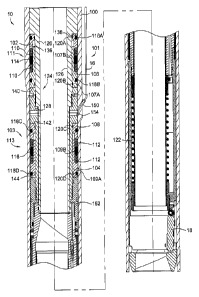
Figure 2 illustrates a sectional view of the SCSSV 10 within a landing nipple
100
as part of the production tubing. The SCSSV 10 is shown in a run-in position
prior to
setting of the SCSSV 10 within the landing nipple 100. As shown, the SCSSV 10
includes an upper seal assembly 101 and a lower seal assembly 103 around its
exterior, a packing mandrel 124 disposed inside the seal assemblies 101, 103,
and an
actuator housing 152 connected to the lower end of the packing mandrel 124. An
exemplary actuator is a spring. The upper seal assembly 101 is compressible
and
includes an upper seal member 111 formed by upper concave seal elements 110
disposed on each side of an upper central sealing element 114. The upper
central
sealing element 114 could be an o-ring, s-seal, or any other type of sealing
element
known in the art. Upper concave seal elements 110 could include V-seals,
chevron
seals, or any other type of sealing element known in the art. An upper first
piston 102 is
6
CA 02829591 2013-10-09
in contact with an upper end of the upper concave seal elements 110, and an
upper
second piston 106 is in contact with a lower end of the upper concave seal
elements
110. The upper second piston 106 comprises an upper piston head 107A and an
upper
piston extension sealing member 107B which may be integrally formed and that
extends between the upper seal member 111 and the mandrel 124. In one
embodiment, the upper piston extension sealing member 107B of the upper second
piston 106 may slide under a portion of the upper first piston 102.
Similarly, the lower seal assembly 103 is compressible and includes a lower
seal
member 113 formed by lower concave seal elements 112 disposed on each side of
a
lower central sealing element 116. The lower central sealing element 116 could
be an
o-ring, s-seal, or any other type of sealing element known in the art. Lower
concave
seal elements 112 could include V-seals, chevron seals, or any other type of
sealing
element known in the art. A lower first piston 104 is in contact with a lower
end of the
lower concave seal elements 112, and a lower second piston 108 is in contact
with an
upper end of the lower concave seal elements 112. The lower first piston 104
comprises a lower piston head 109A and a lower piston extension sealing member
109B that extends between the lower seal 113 and the mandrel 124. In one
embodiment, the lower piston extension sealing member 109B of the lower second
piston 104 may slide under a portion of the lower first piston 108. The
pistons 102, 106,
108, 104 are preferably annular pistons. While both the upper and lower seal
assemblies 101, 103 are shown in the embodiment in Figure 2, the SCSSV 10 may
include only one of either the upper or lower seal assemblies 101, 103.
Additionally,
other variations of the seal members 111, 113 may be used so long as the
pistons 102,
106, 108, 104 can operate to force the seal members 111, 113 into sealing
contact with
the nipple 100.
The packing mandrel 124 includes an upper sub 126 and a middle sub 128
connected together such as by threads. However, the packing mandrel 124 may be
made from an integral member or any number of subs. An annular shoulder 138 on
the
upper sub 126 provides a decompression stop for the upper first piston 102,
which is
slidable along a portion of an outer diameter of the upper sub 126. The upper
piston
extension sealing member 107B of the upper second piston 106 provides a
7
CA 02829591 2013-10-09
compression stop for the upper first piston 102. Likewise, the upper first
piston 102
provides a compression stop for the upper second piston 106. The upper second
piston 106 is slidable along portions of the outer diameter of the upper sub
126 and the
upper piston extension sealing member 107B is slidable between the upper
concave
sealing elements 110 and the upper sub 126. The middle sub 128 is fixed to the
upper
sub 126 and operates to longitudinally separate the upper and lower seal
assemblies
111, 113. The middle sub 128 provides a decompression stop for the upper
second
piston 106 and a decompression stop for the lower second piston 108. The lower
second piston 108 is slidable along a portion of the outer diameter of the
middle sub
128. The lower piston extension sealing member 109B of the lower first piston
104
provides a compression stop for the lower second piston 108. Likewise, the
lower
second piston 108 provides a compression stop for the lower first piston 104.
The
lower first piston 104 is slidable along a portion of the outer diameter of
the middle sub
128 and the lower piston cylinder 109B is slidable between the lower concave
sealing
elements 112 and the middle sub 128. An end face 144 of the actuator housing
152
provides a decompression stop for the lower first piston 104.
The compression and decompression stops operate to limit the sliding
movement of the pistons 102, 106, 108, 104 of the sealing assemblies 101, 103.
Inner
seal members 120 A-D on the inside of the pistons 102, 106, 108, 104 provide a
seal
between each piston and the packing mandrel 124 that the pistons slide along.
Outer
seal members 118 A-D on the outside of the pistons 102, 106, 108, 104 provide
an
initial seal between each piston and the nipple 100. The outer seals 118 may
be soft o-
rings, or any other type of seal known in the art, with a large cross section
to help
ensure a sufficient initial seal between the pistons 102, 106, 108, 104 and
the nipple
100. Thus, the initial seal provided by the outer seal members 118
sufficiently seals
against the nipple 100 such that fluid pressure applied to the large surface
areas of the
pistons 102, 106, 108, 104 that are shown in contact with the decompression
stops
138, 140, 142, 144 causes the pistons to slide along the packing mandrel 124
toward
the respective seal 111, 113.
In the run in position of the SCSSV 10 as shown in Figure 2, the seal
assemblies
101, 103 are in uncompressed positions with all the pistons 102, 106, 108, 104
8
CA 02829591 2013-10-09
. ,
contacting their respective decompression stops 138, 140, 142, 144. Therefore,
the
upper and lower seal members 111, 113 are not compressed and may not provide
sealing contact with the inside surface of the nipple 100 and the outside of
the packing
mandrel 124. During run-in all parts of the SCSSV 10 are in equal pressure so
that the
pistons 102, 106, 108, 104 do not move. In the run-in position, the SCSSV 10
is
temporarily held open by a running tool (not shown) using a run-in prong or
other
temporary opening member. Since the SCSSV 10 is open, wellbore fluid pressure
does not act on the first pistons 102, 104 to compress the upper and lower
seal
members 111, 113. Further, fluid pressure is not supplied through the control
line 16
such that the second pistons 102, 106 are also not acted on to compress the
upper and
lower seal members 111, 113.
Once the SCSSV 10 is set or locked in the nipple 100 by conventional methods,
the temporary opening member disengages and permits normal functioning of the
SCSSV 10. Thus, the flapper 18 biases to a closed position unless fluid
pressure is
supplied through the control line 16 to a port 150 in the nipple 100 in order
to actuate
the SCSSV 10.
Figure 3 is a sectional view of the SCSSV 10 in an actuated open position with
the seal assemblies 101, 103 in a first compressed position. Fluid pressure
supplied
through the control line 16 to the port 150 in the nipple 100 passes through a
fluid
passageway 154 into an annular area outside the upper sub 126. The fluid
pressure
acts on a piston rod 158 connected to a flow tube 122 to force the flow tube
down
against the bias of a biasing member such as a spring 146. The longitudinal
displacement of the flow tube 122 causes the flow tube 122 to displace the
flapper 18
and place the SCSSV 10 in the actuated open position. As an example of an
SCSSV
actuated by a concentric piston, the fluid pressure may alternatively act on
an outward
facing shoulder of a flow tube located concentrically within the packing
mandrel to force
the flow tube down and open a flapper.
The fluid pressure supplied through the control line 16 used to actuate and
open
the SCSSV 10 additionally operates to place the seal assemblies 101, 103 in
the first
compressed position. The fluid pressure supplied from the control line 16
enters the
9
CA 02829591 2013-10-09
port 150 where the fluid enters the interior of the nipple 100 and acts on the
second
pistons 106, 108 to slide the second pistons 106, 108 toward the respective
seal
members 111, 113. Any wellbore pressure on the first pistons 102, 104 is less
than
that on the second pistons 106, 108 such that the first pistons 102, 104
remain in
contact with their respective decompression stops 138, 144. The sliding
movement of
the second pistons 106, 108 pushes on the concave sealing elements 110, 112,
which
in turn pushes on the central sealing elements 114, 116. Compression of the
seal
members 111, 113 caused by the sliding of the second pistons 106, 108 forces
the
central sealing elements 114, 116 and/or the concave sealing elements 110, 112
into
sealing contact with the inside surface of the nipple 100. Preferably, the
central sealing
elements 114, 116 are soft o-rings with a large cross section made from a
material such
as Viton (65 duro). However, the central sealing elements 114, 116 could be S-
Seals
or any other type of sealing element known in the art. Additionally, the
chevrons 110,
112 are preferably made from a material such as Key!are filled Viton , but
also could
be any other sealing element known in the art. Once the SCSSV is actuated
open,
wellbore fluid passes through the SCSSV 10 such that wellbore fluid pressure
does not
act to slide the first pistons 102, 104, and the first pistons 102, 104 remain
in contact
with their respective decompression stops 138, 144.
Figure 4 is a sectional view of the SCSSV 10 set in the nipple 100 and biased
to
the closed position with the seal assemblies 101, 103 in a second compressed
position
and the flapper 18 blocking fluid flow through the SCSSV 10. As fluid pressure
bleeds
from the control line 16 during closure of the SCSSV 10, the fluid pressure
acting on the
second pistons 106, 108 approaches hydrostatic pressure, which along with the
wellbore pressure acting on the first pistons 102, 104 keeps the seals 111,
113
compressed. When the wellbore pressure is greater than the pressure supplied
by the
control line 16, the wellbore pressure acts on the first pistons 102, 104 to
slide the first
pistons 102, 104 toward the respective seal members 111, 113. For example,
wellbore
fluid pressure above the SCSSV 10 acts on the upper first piston 102, and
wellbore
fluid pressure below the SCSSV 10 acts on the lower first piston 104. The
second
pistons 106, 108 slide into contact with their respective decompression stops
140, 142.
The sliding movement of the first pistons 102, 104 pushes on the concave
sealing
CA 02829591 2013-10-09
. .
elements 110, 112, which in turn pushes on the central sealing elements 114,
116.
Therefore, compression of the seal members 111, 113 caused by the sliding of
the first
pistons 102, 104 maintains sealing contact with the inside surface of the
nipple 100
since the central sealing elements 114, 116 and/or the concave sealing
elements 110,
112 remain forced against the inside surface of the nipple 100.
In both the first and second compressed positions as illustrated by Figures 3
and
4 respectively, the upper and/or the lower seal members 111, 113 form a fluid
seal with
an inside surface of the nipple 100 that may have irregularities, grooves,
recesses,
and/or ridges that would prevent prior SCSSVs from properly sealing within the
nipple
100. Additionally, the sealing ability of the upper and/or the lower seal
members 111,
113 with the concave sealing elements 110, 112 around the central sealing
members
114, 116 increases with increased pressure to the pistons 102, 106, 108, 104.
As
shown, the SCSSV provides an annular recess to provide a flow path to operate
the
SCSSV, and the seal assemblies 101, 103 do not interfere with the flow path
through
the SCSSV 10.
A method for sealing an SCSSV within a nipple located in a well is provided by
aspects of the invention. The method includes locating the SCSSV in the nipple
using
conventional running methods. The SCSSV includes at least one seal assembly
disposed about an outer surface thereof, and the at least one seal assembly
includes a
seal member, a first piston disposed on a first side of the seal member, and a
second
piston disposed on a second side of the seal member. Urging the first piston,
the
second piston or both the first and second pistons toward the seal member
forces the
seal member into sealing contact with an inside surface of the nipple. Urging
the first
piston is caused by wellbore fluid pressure applied to the first piston when
the SCSSV
is closed. Urging the second piston is caused by fluid pressure supplied from
a control
line to a fluid port in fluid communication with an inside portion of the
nipple.
Other seal assemblies 111, 113 are also contemplated within the current
invention. Figure 5 illustrates one embodiment of a seal assembly 200 that
could be
used in place of one or both of the seal assemblies 101, 103 shown in Figures
2-4. The
seal assembly 200 may include a compressible sealing member 205 formed by a
11
CA 02829591 2013-10-09
central sealing element 210 located between concave sealing elements 220 such
as V-
seals or chevrons, or any other sealing element known in the art on each side
of the
central sealing element 210. A mandrel 124 includes a first, second, and third
shoulder
230, 232, 234 (respectively), and further includes a first recess 235 located
between the
first and second shoulders 230, 232, and a second recess 245 located between
the
second and third shoulders 232, 234. The compressible sealing member 205 is
positioned between the first recess 235 and the nipple 100 and is located at a
first end
of the first recess 235. A piston 240 is adjacent the compressible sealing
member 205,
and is located at a second end of the first recess, as well as within the
second recess
245. The piston 240 is slidable along the first and second recesses 235, 245,
and has
end stops at the second and third shoulders 232, 234. The piston 240 may
include
sealing elements 270B, 280B for providing an initial seal between the nipple
100 and
the mandrel 124. The piston 240 slides between the nipple 100 and the first
and
second recesses 235, 245 to compress the compressible sealing member 210. As
the
piston 240 is moved toward the compressible sealing member 205, a seal is
formed
between the nipple 100 and the first recess 235 of the mandrel 124.
Figure 6 illustrates another embodiment of a seal assembly 300 that could be
used in place of one or both of the seal assemblies 101, 103 shown in Figures
2-4.
Seal assembly 300 may include a compressible seal member 305 formed by a
central
sealing element 310 located between concave sealing elements 320 such as V-
seals or
chevrons, or any other sealing element known in the art on each side of the
central
sealing element 310. A first sealing element 330 is in contact with a shoulder
335
adjacent to a first end of the concave sealing elements 320, and a second
sealing
element 340 in contact with a second shoulder 345 adjacent to a second end of
the
concave sealing elements 220. The first and second sealing elements 330, 340
may
be o-rings, s-type seals, polypacks, or any other type of seal known in the
art, and may
provide an initial seal against the nipple 100 and the mandrel 124. The
mandrel 124
provides a stop to the first and second sealing elements 330, 340. As pressure
is
applied to the first and second sealing elements 330, 340, the first and
second sealing
elements 330, 340 are compressed and slide along packing sub 124, which then
compresses the concave sealing elements 320 and the central sealing element
310.
12
CA 02829591 2013-10-09
When the concave sealing elements 320 and the central sealing element 310 are
compressed, a seal is formed against the inside surface of the nipple 100.
Figure 7 illustrates another embodiment of a seal assembly 400 that could be
used in place of one or both of the seal assemblies 101, 103 shown in Figures
2-4. The
seal assembly 400 may include a compressible seal member 405 formed by a
central
sealing element 410 located between concave sealing elements 420 such as V-
seals or
chevrons on each side of the central sealing element 410. A first piston 430,
which
comprises a sealing element such as an o-ring or any other sealing element
known in
the art, and a first packing retainer 450 are adjacent to a first end of the
concave
sealing elements 420. A second piston 440, which comprises a sealing element
such
as an o-ring or any other sealing element known in the art, and a second
packing
retainer 460 are adjacent to a second end of the concave sealing elements 420.
The
second packing retainer 460 includes a packing retainer extension 465, and the
packing retainer extension 465 slides between the concave sealing elements 420
and
the middle sub 128, and provides a compression stop for first piston 430. In
addition to
acting as pistons to the seal assembly 400, the first and second pistons 430,
440 also
provide an initial seal between the nipple 100 and the middle sub 128. As
pressure is
applied to the first and second pistons 430, 440, the first and second pistons
430, 440
are compressed, and move toward the compressible seal member 405, thereby
resulting in the compressible seal member 405 forming a seal against the
nipple 100.
While the foregoing is directed to embodiments of the invention, other and
further embodiments of the invention may be devised without departing from the
basic
scope thereof, and the scope thereof is determined by the claims that follow.
13