Note: Descriptions are shown in the official language in which they were submitted.
CA 02829706 2013-09-10
dT
QIAGEN Instruments AG
Garstligweg 8, CH ¨ 8634 Hombrechtikon
"Device for closing a sample container with a spherical closing element"
The invention relates to a device for closing a sample container with a
spherical closing
element, and also a system comprising such a device and a corresponding sample
container.
Sample containers are used in particular within the scope of biotechnological
methods
in order to process a biological sample or a biological material, such as a
sample
containing nucleic acids. These sample containers can be used for example to
duplicate nucleic acids in vitro within the scope of amplification reactions,
such as a
polymerase chain reaction (PCR). Here, the sample containers are used to
receive the
sample comprising the nucleic acids.
A large number of different sample containers that are routinely used as
disposable
products within the scope of appropriate biotechnological methods, such as
PCR, are
known from the prior art. Here, the sample containers are firstly filled with
the sample,
then closed in an airtight manner, and lastly supplied to the PCR process.
Here, high
demands are placed on the closure of the sample containers. On the one hand,
the
sample containers have to be reliably tightly sealed so as not to compromise
the result
of the PCR process by the entry and exit of sample material or by an undesired
pressure change. On the other hand, a large number of samples and therefore of
sample containers are routinely used within the scope of a PCR process and
have to
be filled and closed. This should therefore be performed in an automated
manner
where possible. Furthermore, it must be possible to produce the sample
containers
cost-effectively, in particular because they are required in high number and
are used as
disposable products.
A sample container is known from EP 0 449 425 A2, wherein one end of a
cylindrical
housing, which forms a sample space, is provided with a circular opening that
extends
in a channel-shaped manner into the sample space. The opening channel tapers
shortly before the transition into the sample space and thus forms a seal seat
for a
spherical closing element. Once the closing element has been fitted onto the
seal seat,
it is fixed by means of a closing plug.
As a three-part system, the sample container known from EP 0 449 425 A2 is not
only
relatively complex and therefore expensive, but can also only be closed in an
automated manner with relatively high effort.
CA 02829706 2013-09-10
- 2 L
Proceeding from this prior art, the object of the invention was to specify a
system
comprising a sample container and a device, said system ensuring reliable
automated
closure of the sample container.
This object is achieved by a device according to independent claim 1 and by a
system
comprising such a device and a sample container according to independent claim
12.
Independent claim 16 relates to a storage container which is to be used in
conjunction
with the device according to the invention according to claim 1. Advantageous
developments of the device according to the invention, of the system according
to the
invention and of the storage container according to the invention are
disclosed in the
respective dependent claims and will emerge from the following description of
the
invention.
The system according to the invention comprises a sample container which has a
housing which forms a sample space for receiving a sample and has at least one
spherical opening, which extends in a channel-shaped manner into the sample
space.
The sample container can be closed by means of a spherical closing element,
the
diameter of the closing element exceeding the diameter of the opening channel
in at
least one (closing) portion only to an extent that one of the closing elements
can be
fixed in a force-locked manner by its largest circumference in the closing
portion.
The force-locked fixing of the closing element by contact between a region
comprising
the largest circumference of the spherical closing element and the wall of the
opening
channel is important in order to achieve a secure fixing. The resultant forces
with this
type of force-locked fixing specifically comprise no, or only a relatively
small (and
therefore negligible), force components in the longitudinal axial direction of
the opening
channel, but these are directed (largely) radially in the direction of the
centre of the
spherical closing element. Sufficient fixing and, at the same time, a good
sealing effect
can thus be produced with only a relatively small (preferably elastic)
deformation of the
closing element and of the wall of the opening channel. A small deformation
then also
requires only relatively small forces in order to introduce the closing
element into the
opening channel. This can not only simplify the automation of the closing of
the sample
container but also enable manual closing of the sample container. In addition,
the
requirements of the materials used for the closing element and the housing are
reduced, whereby the production costs for the sample container can be kept
low.
In the case of the sample container of the system according to the invention,
the
spherical closing element not only effects sealing in conjunction with the
housing of the
sample container, but it is reliably fixed without additional retaining means,
for example
a closing plug, as is known from the sample container in EP 0 449 425 A2. Such
a
CA 02829706 2013-09-10
- 3 -
sample container can accordingly be closed easily in an automated manner in
that the
closing element is merely driven in a suitable manner into the opening channel
of the
housing.
In order to close such a sample container, the system according to the
invention has a
device which comprises a storage container for a plurality of spherical
closing elements
and also ejecting means for ejecting one of the closing elements through a
discharge
opening in a housing of the device. Thus, in order to close the sample
container, one of
the spherical closing elements is driven by means of the ejecting means of the
device
into the opening channel of the housing of the sample container and is fixed
in a force-
locked manner there.
Provided in the device according to the invention are means which limit the
forces
exerted by the ejecting means (preferably ram) on the closing element. These
can
serve to limit the loading of the closing element or of the housing, loaded
thereby, of a
sample container. In particular, the advancement control of the ram can be
subjected to
less stringent requirements as a result, since an excessive stroke of the ram
can be
compensated by the force limitation and thus excessive driving of the closing
element
into the opening channel of the sample container can be avoided.
The means for force limitation can be formed preferably as (at least one)
spring which
is arranged for example between the ram and the drive means which effect the
periodic
movement of the ram. An excessive stroke of the ram can then be compensated by
an
elastic deformation of the spring. Of course, it is also possible to arrange
the spring at
any desired point in the force flow between the drive means and the support of
the
sample container. For example, the sample container can be spring-mounted in a
receptacle or the receptacle is spring-mounted in a corresponding manner. The
spring
is preferably integrated into the device in a preloaded manner in order to
allow it to
respond only when a defined force is exceeded.
On the other hand, it is of course also possible to control the introduction
of force by
the ejecting means onto the closing element by electronic control of the
ejecting
movement.
In a preferred embodiment of the device for closing, the ejecting means may
comprise
a ram. This makes it possible to drive one of the closing elements into the
opening
channel of the sample container in a structurally simple manner.
Since the device according to the invention for closing a multiplicity of
sample
containers is preferably used with a short cycle, the ram may preferably be
driven by
means of suitable drive means in a periodic (to-and-fro) movement. The device
should
CA 02829706 2013-09-10
- 4
then be used in combination with an apparatus which, in a cycle corresponding
to the
periodic movement of the ram, either supplies the individual sample containers
to be
closed to the device according to the invention or allows the device according
to the
invention to discharge the individual sample containers in succession.
The drive means for the periodic movement of the ram may preferably have a
rotary
drive which is connected to the ram via a gear mechanism in order to convert
the rotary
movement of the rotary drive into the periodic translation movement of the
ram.
In a preferred embodiment, the rotary drive may for this purpose have a drive
disc on
which a bolt is decentrally arranged, which is guided in a slot of the ram or
of a guide
element connected to the ram, wherein the alignment of the slot is not
parallel to (also
not coaxial with) the direction of movement. As a result, the rotary movement
of the
drive disc can be converted into a periodic translation movement of the ram in
a
structurally simple manner. In order to drive the ram in a periodic
translation
movement, use can be made for this purpose of rotary drives (in particular
electric
rotational motors) which are available cost-effectively on the market. Of
course, it is
also possible to provide any other desired connection between the drive disc
and the
ram or the guide element of the ram.
The drive means can of course also be formed in any other desired manner, for
example by way of a toggle lever mechanism or (any desired) linear motor, for
example
in the form of a plunger-type armature ("solenoid") which is movably guided in
an
electrically loaded coil.
In order to achieve smooth operation of the device according to the invention
and in
particular to ensure that in each case only one closing element is entrained
by the ram
and driven into the opening channel of the housing of a sample container, the
device
according to the invention can preferably comprise a separating apparatus.
This can
preferably comprise a feed channel in which the closing elements are arranged
in
succession and via which these are fed in succession to a transfer position
located in
the movement path of the ram. The movement of the closing elements in the feed
channel can in this case take place as a result of the force of gravity.
Alternatively or in
addition, any other desired transport means, for example means for exerting
vibrations
or compressed-air transport means, can also be used.
The device according to the invention can furthermore have a barrier element
which
temporarily fixes the individual closing elements in the transfer position.
The fixing of
the respective closing element by the barrier element is preferably only
released when
the ram entrains it. This can be achieved in a simple manner by means of a
spring-
loaded or spring-mounted barrier element which is laterally displaced when the
force
CA 02829706 2013-09-10
- 5
exerted by the ram on the closing element is exceeded, such that the movement
path
of the closing element is released.
In a further preferred embodiment of the device according to the invention,
the latter
has supporting means for supporting the transport of the closing element from
the
storage container to the ejecting means. These may act preferably in a
vibrating and/or
pneumatic manner. The supporting means can effect transport in isolation or
only
support transport, for example exert transport in conjunction with transport
as a result
of the force of gravity.
Preferably, the ram may be integrated in an exchangeable manner in the device.
Such
a configuration is expedient in particular in the case of a use for closing
sample
containers for a biotechnological method, for example a PCR process, since
particular
requirements are placed on sterility there. The exchangeable integration of
the ram into
the device thus allows simple and cost-effective maintenance in order to meet
the
sterility requirements for such applications. Alternatively or in addition
thereto, the ram
may also be provided with an exchangeable (surface) cover. This embodiment can
make it possible to meet the requirement of sterility of the system with ¨
compared with
an exchangeable ram ¨ lower costs.
Preferably, the device has at least one sensor for sensing the ejection of a
closing
element, the filling level of the storage container and/or the force exerted
by the ram on
the respective closing element. Such a sensor makes it possible to monitor and
document the closing process.
In a preferred embodiment of the system according to the invention, the
contact area of
the ram which comes into contact with the closing element during ejection may
be
configured in a larger manner than the external cross-sectional area of the
opening
channel of the housing of the sample container. As a result, the portion of
the housing
that surrounds the opening channel can serve as a (maximum) stop for the ram,
as a
result of which it is possible to prevent the closing element from being
driven further
than intended into the opening channel of the housing. In addition, the
relatively large
area of the ram can ensure that reliable closing can be achieved even in the
case of
relatively imprecise positioning of the device relative to the housing of the
sample
container. This embodiment should preferably be combined with means for
limiting the
forces exerted by the ejecting means on the closing element, in order to avoid
damage
to the sample container.
The system according to the invention can furthermore have a sensor which can
determine the position of the closing element in the housing of the sample
container.
This too may be expedient or necessary to check and document the closing
process.
CA 02829706 2013-09-10
. .
- 6 1
One possibility for this purpose may be to form the housing of the sample
container in
an optically transparent manner at least in one portion of the closing
portion, with the
sensor comprising means for detecting the refractive index of the housing
material in
the transparent portion. The operation of the sensor can accordingly be based
on
determining a change to the refractive index, this change being caused by the
fact that,
during the transition of the light from a first solid (wall of the opening
channel at the
location at which the closing element is positioned) to a second solid
(closing element),
there is no total reflection at the inner wall of the opening channel,
whereas, in the
event of a transition from a solid (wall of the opening channel) to air (or
another gas),
there is partial reflection at the inner wall.
Preferably the housing may form a shoulder for forming a bearing surface. The
forces
that are to be applied to introduce the closing element (typically from 60 N
to 130 N, at
most 250 N) can be supported at a holder supporting the sample container via
said
bearing surface. In particular, the bearing surface can be formed at a point
of the
housing that is located in the vicinity of the closing portion of the opening
channel. It is
thus possible to prevent the forces from being transmitted via other portions
of the
housing, which may be formed with thinner wall thicknesses and may therefore
be
more sensitive (in particular the wall of the housing surrounding the sample
space).
A storage container for use in a device according to the invention has a
housing and a
guiding and/or bearing apparatus arranged within the housing, a plurality of
spherical
closing elements being arranged alongside one another in a row therein.
Preferably, the guiding and bearing apparatus can have a guiding and bearing
channel
that extends in a spiral shape.
Further preferably, the housing of the storage container may have a filling
opening
which is closed non-releasably with the closing elements after the storage
container
has been filled. Accordingly, such a storage container is preferably provided
according
to the invention as a single use product, which can be advantageous in
particular for
sterility reasons. From this point of view, it is also possible for the
ejecting means (in
particular the ram) to be integrated in the storage container provided as a
single use
product.
The invention will be explained in greater detail hereinafter on the basis of
exemplary
embodiments illustrated in the drawings.
In the drawings:
figure 1: shows a sample container of a system according to the invention;
CA 02829706 2013-09-10
-7
figure 2: shows a detail of the sample container of figure 1 in
a sectional side
view;
figure 3: shows a further detail of the sample container of
figure 1 in a
sectional side view;
figure 4: shows the introduction of the closing element into the sample
container according to figures 1 to 3 by means of a ram in a first
embodiment;
figures 5 and 6: show the introduction of a closing element into a
sample container
according to figure 1 by means of a ram in a second embodiment;
figure 7a: shows the force curve when introducing closing elements into
sample containers according to figures 1 to 3 with use of a ram
according to figure 4;
figure 7b: shows the force curve when introducing closing
elements into
sample containers according to figures 1 to 3 with use of a ram
according to figures 5 and 6;
figures 8a and 8b: show a sample container of a system according to the
invention in a
second embodiment in two different sectional illustrations;
figures 9a and 9b: show a sample container of a system according to the
invention in a
third embodiment;
figure 10: shows a sample container of a system according to the invention
in
a fourth embodiment;
figure 11: shows a storage container of a device according to the
invention for
automatically closing sample containers in a first embodiment;
figure 12: shows a closing unit of a device for the automated
closing of sample
containers according to the invention;
figure 13: shows a basic illustration of the operating principle
of the closing
unit according to figure 12;
figure 14: shows an isometric view of a storage container of a
device
according to the invention for automatically closing sample
containers in a second embodiment;
figure 15: shows the storage container according to figure 14 in
combination
with a closing unit in a longitudinal section;
figure 16: shows the storage container according to figure 14 in
combination
with an alternative closing unit in a longitudinal section;
figure 17: shows the integration of the components according to figure 11
and
12 in an automated closing device;
figure 18: shows the integration of the automated closing device
according to
figure 17 in a device for carrying out a PCR;
figure 18: shows a schematic illustration of an alternative
supply of closing
elements to a device for the automated closing of sample containers
according to the invention; and
CA 02829706 2013-09-10
-8
figures 20a to 20f: show comparisons of a "normal" force curve to deviating
force
curves, produced by various causes.
Figure 1 shows a sample container 1 according to the invention in a first
embodiment.
The sample container 1 comprises a housing 2, which is formed in a first
portion (head
portion 3) and a second portion (middle portion 4) with a largely cylindrical
lateral
surface. The lateral surface has just a small conical tapering, which is used
in order to
more easily demold the housing 2 consisting of plastic after injection
molding. The end
of the middle portion 4 opposite the head portion 3 is adjoined by an end
portion 5, in
which the housing 2 tapers and is therefore formed in a tapering manner in the
broader
sense. In the end portion 5, the housing 2 is formed from an (optically)
transparent
material, which enables the use of optical measuring elements within the scope
of a
biotechnological method, such as a PCR process, in which the sample container
1 is to
be used.
On the outer face between the head portion 3 and the middle portion 4, the
housing 2
forms a shoulder 6, which is used as a bearing surface, via which the housing
2 is
supported on a sample container support 7 (see figure 2).
Within the middle portion 4 and the end portion 5 of the housing 2, a sample
space is
formed, wherein the wall thickness of the housing 2 in these two portions is
largely
constant, such that a sample space portion which is again largely cylindrical
is formed
within the middle portion 4, and a conically tapering sample space portion
formed with
a rounded tip is formed in the end portion 5 of the housing 2.
In the head portion 3 of the housing 2, an opening channel is formed, which
makes it
possible to fill the sample container 1 with the sample to be examined. After
filling, the
sample space is closed by the introduction of a spherical closing element 8 in
the
manner according to the invention. The closing effect, that is to say both the
sealing
and the fixing of the closing element 8 in the opening channel, is achieved in
that the
largest outer diameter of the closing element 8 is slightly larger than the
opening
channel in a defined portion (closing portion 11) (see figure 2) and the
closing element
8 is therefore fixed in a wedged manner in the opening channel.
Starting from the upper (free) end of the head portion 3, the opening channel
is first
provided with an entry chamfer 9, which defines a relatively (based on the
outer
diameter of the closing element 8) large opening cross section (largest
diameter: 4.5
mm). The entry chamfer 9 facilitates the central positioning of the closing
element 8
(largest diameter 4.1 mm to 4.2 mm). The entry chamfer 9 transitions into a
first
annular protrusion 10, which reduces the opening cross section (diameter: 3.7
mm) of
the opening channel compared to the opening cross section in the closing
portion of
CA 02829706 2013-09-10
- 9
the opening channel (diameter: approximately 4.0 mm). In order to introduce
the
closing element 8 into the opening channel, it is loaded by a force
(component) which
is directed coaxially with or parallel to the longitudinal axis of the housing
2, specifically
in the direction of the end portion of the housing 2.
The force is so great that it leads to a deformation both of the housing 2 in
the region of
the head portion 3 and of the closing element 8 itself, which makes it
possible for the
closing element 8 to pass the first protrusion 10 and to be inserted as far as
the closing
portion 11 of the opening channel. There, the closing element 8 is fixed in a
force-
locked manner, that is to say wedged, by means of its larger (maximum)
diameter
compared to the diameter of the opening channel in the closing portion 11.
Here, the
forces are achieved by a (largely elastic) deformation of the housing 2 in the
region of
the closing portion 11 and also of the closing element 8. Due to the
symmetrical force-
locked fixing of the spherical closing element 8 in the region of its largest
cross section,
the reaction forces that act from the wall of the opening channel onto the
ball (and vice
versa) do not have any component in the longitudinal axial direction of the
housing.
Once introduced into the closing portion 11, the closing element 8 is thus
securely held,
provided no significant external forces act thereon in the longitudinal
direction of the
housing 2.
The first protrusion 10, which has to be passed by the closing element 8 when
introduced into the closing portion 11, is used on the one hand as an end stop
that
prevents the closing element 8 from being slid out from the opening channel in
the
event of the creation of an overpressure within the closed sample space, for
example
caused by heating within the scope of a biotechnological method, such as a PCR
process, and thus prevents the sample container 1 from being opened
undesirably.
Furthermore, this protrusion 10 is used to produce a force curve which is
characteristic
as the closing element 8 is introduced and on the basis of which an actual
introduction
of the closing element 8 as far as the closing portion 11 can be detected (in
the manner
of a locking into place).
The transition of the opening channel into the sample space of the housing 2
is formed
as an annular shoulder. This shoulder constitutes a second protrusion 12,
which is
used as an end stop for the closing element 8 and therefore delimits the
closing portion
11 of the opening channel on the side of the sample space.
The length of the closing portion 11 of the opening channel is dimensioned
such that
the closing element 8 can be displaced therein over a specific distance x
before it
contacts one of the two protrusions 11, 12 (see figure 3). This distance is
limited in the
present case to 0.7 mm at most, since experience has demonstrated that, with a
CA 02829706 2013-09-10
- 10'-
displacement of this type of the closing element 8, the process parameters (in
particular pressure, temperature) within the sample space only change to such
a small
extent that no significant (negative) effects on the biotechnological method,
such as the
PCR process, are to be feared. This positional tolerance of the closing
element 8 within
the closing portion 11 also has the advantage that relatively large tolerances
in the
production of the housing 2 and of the closing element 8 can be specified,
whereby the
corresponding tools can be subject to less stringent requirements.
Figures 4 to 6 show the use of a ram 13 (in two embodiments) in order to slide
the
closing element 8 into the opening channel. In the embodiment according to
figure 4,
the ram 13 has an outer diameter of 3.6 mm (or smaller), which is therefore
smaller
than the inner diameter of the opening channel in the region of the first
protrusion 11.
The ram 13 can therefore dip into the opening channel. To this end, the
movement of
the ram should be controllable in a precise manner in order to prevent said
ram from
pressing the closing element 8 with force against the second protrusion
serving as an
end stop, which could lead to damage of the housing 2 or of the closing
element 8. In
the embodiment of a ram 13 according to figures 5 and 6, the outer diameter of
the ram
3 is therefore considerably larger than the inner diameter of the opening
channel in the
region of the entry chamfer 9. The movement of the ram 13 is therefore
delimited at the
latest by the fact that it contacts the free end of the housing 2. A pressing
of the closing
element 8 by means of the ram against the second protrusion 12 serving as an
end
stop can therefore be easily avoided. A further advantage of the large contact
area of
the ram 13 is that the closing element 8 can be pressed in steadily without
difficulty,
even if the ram 13 is not arranged exactly centrally above the closing element
8 (see
figure 6).
Figure 7a shows an exemplary force curve (force F over the ram path I) for a
closing
process with use of a ram according to figure 4. In a first portion (a) of the
force curve,
the force is practically zero; this portion defines the displacement of the
ram 13 until it
contacts the closing element 8. This is followed in a second portion by a
sharp rise of
the force as far as a first maximum value (b) (first extreme point of the
curves), which is
necessary in order to allow the closing element to pass the first protrusion
10. This
force then falls as far as a second extreme point (c), which defines the force
(which is
then only slightly rising due to the slightly conical design of the opening
channel, see
portion (d)) which is necessary to displace the ball in the closing portion
11. This force
corresponds substantially to the force that is produced from the friction
between the
wall of the opening channel in the closing portion 11 and the contacting
portion of the
closing element 8. If a closing process is carried out correctly, the exertion
of force
ends anywhere in portion (d) of figure 7.
CA 02829706 2013-09-10
. .
- 11'- .
If the ram 13 dips too deeply into the opening channel however, the closing
element
may be pressed thereby against the second protrusion 12, which is again
evidenced by
a sharp rise in force (portion (e)). This rise may be limited (that is to say
in accordance
with the depth of dip of the ram 13) by the breaking load of the sample
container 1
(and, where appropriate, also of the closing element 8 or of the ram 13)
((f)), whereby
the force falls to a considerably lower level (portion (g)).
Figure 7b shows a corresponding exemplary force curve for the use of a ram
according
to figures 5 and 6. The force curve in portions (a) and (d) as well as
therebetween
corresponds to that in figure 7a. After portion (d), there is then a rise in
force (h), which
is sharper than that with the curve according to figure 7a. This is produced
as a result
of the contact between the ram 13 and the edge of the sample container 1. The
ram 13
should then only be moved further over a relatively short path in order to
avoid
overloading the sample container 1 (or the ram 13). To control the stroke of
the ram,
the force curve can be evaluated such that, for example once the end of the
portion (h)
has been reached, a (force) limit value is reached, which for example may lead
to a
deactivation of a ram drive. In figure 7b, the further force curve that leads
to a rupture
of the sample container due to overload is also illustrated with a dashed line
arrangement. This is characterized by a continuation of portion (h) (portion
(i)), at the
end of which the rupture occurs. This is characterized by a direct fall in
force to a level
close to zero (portion (k)).
Figures 20a to 20f show exemplary deviations from the "normal" force curves
described
previously. It is possible to determine the appropriate fault source from
these
deviations. Here, the deviating force curve is illustrated by a continuous
line, whereas
the "normal" force curve is shown in a dashed manner. Figure 20a shows two
deviating
force curves, wherein the dimensioning or the material properties of the
sample
container in the region of the opening channel and/or of the closing element
are not
correct. Figure 20b shows two deviating force curves, wherein the vertical
alignment of
the closing element, that is to say the distance between the closing element
and the
ram, is too little or too large. In the case of the deviating force curve
according to figure
20c, the horizontal alignment is not correct, that is to say there is
insufficient conformity
between the longitudinal axes of the sample container and of the ram. This may
lead to
an impairment of the movement of the closing element. Figure 20d shows a
deviating
force curve which is produced if there is a fault concerning the closing
element and the
ram moves without substantial application of force until colliding with the
sample
container. The deviating force curve illustrated in figure 20e can be produced
if the
contact surfaces of the closing element and/or of the sample container do not
correspond to the requirements. By contrast, figure 20f shows a deviating
force curve
which can be produced in the event of the rupture of a sample container.
CA 02829706 2013-09-10
- 12'-
Figures 8a and 8b show a second embodiment of a sample container 1, wherein
two
closing elements 8 are fixed in a force-locked manner in a common closing
portion 11
of the housing 2. A second sample space is thus formed between the two closing
elements 8. The corresponding embodiment of the opening channel, by contrast
with
the illustration in figure 8, can be selected arbitrarily in accordance with
the exemplary
embodiment according to figures 1 to 3, that is to say in particular can be
provided with
one or more protrusions. Furthermore, a bypass channel 14 is formed in the
wall of the
housing between the lower sample space and the closing portion 11 and also
between
the closing portion 11 and the upper, open end of the sample container 1. The
upper
bypass channel 14 is used to balance an overpressure in the two sample spaces,
which would otherwise be produced as a result of the relatively deep
introduction of the
closing elements. By contrast, the lower bypass channel 14 is provided, for
example
within the scope of the PCR process, to transfer a sample contained in the
upper
sample chamber into the lower sample chamber, as is illustrated in figure 8a.
To this
end, the lower closing element 8 is slid by means of the upper closing element
8 into
the portion of the opening channel/sample space comprising the lower bypass
channel
14, such that the sample can flow from the upper sample chamber via the lower
bypass
channel 14, past the lower closing element 8, and into the lower sample
chamber.
Figures 9a to 9b show a sample container 1 in a further embodiment, in which
said
sample container is to be opened again by pressing the closing element 8 by
means of
a ram 13 completely into the sample space as far as the closed end. The sample
liquid
displaced during this process can flow off via a bypass channel 14 formed on
one side
in the wall of the housing 2 and can thus be removed from the sample container
1.
Figure 10 shows a sample container 1, wherein the housing 2 is provided in the
region
of the sample space with a varying wall thickness. In the region of the sample
space
which receives the sample, the housing 2 has a minimal wall thickness, for
example
from 0.2 to 0.3 mm. A thin wall thickness simplifies the examination of the
sample by
means of optical methods. In a portion of the sample space which forms a dead
space
(that is to say with no sample contained therein), the wall thickness is
thicker, by
contrast (for example twice as thick, for example 0.4 to 0.6 mm), whereby not
only can
the mechanical stability of the housing 2 be increased, but in particular also
an
evaporation of the sample through the housing 2 can be reduced.
Figures 11 and 12 show individual components of an automated closing device
(see
figure 17) which is to be used in a device for carrying out a PCR process (see
figure
18).
Here, figure 11 shows a storage container 15, in which a drawn-out guide 16
running in
a spiraled manner is arranged and is used to receive and guide a multiplicity
of closing
CA 02829706 2013-09-10
. .
- 13'- .
elements 13 of a sample container 1. The lower end of the guide 16 ends in an
outlet
opening, via which the closing element can be transferred to a closing unit
17, as is
illustrated in part in figure 12. The storage container 15, which can be sold
as a filled
disposable container, can be fastened for this purpose to the front end of the
closing
unit 17.
The closing unit 17 comprises an electric motor arranged in a housing 18, said
electric
motor being able to drive a drive disc 19 in rotation. The drive disc 19 is
provided
decentrally with a bolt 20, which is guided in a slot 21 of a ram guide 22.
The guidance
of the bolt 20 in the slot 21 translates the rotational movement of the drive
disc 19 into
a cyclical upward and downward movement of the ram guide 22, inclusive of a
ram 13
fastened thereto, as is illustrated in principle in figure 13. With each
downward
movement of the ram 13, a closing element 8 held in a transfer position is
entrained
and is pressed via a discharge opening of the closing unit into the opening
channel of a
housing 2 of a sample container 1 arranged therebelow (not illustrated in
figure 13).
Once the ram 13 has been raised again, a further one of the closing elements 8
stored
temporarily in succession in a feed channel 23 can then roll (as a result of
the force of
gravity) into the transfer position, where it is held via a spring-mounted
barrier element
24. With the subsequent downward movement of the ram 13, the next closing
element
8 is then entrained, wherein the barrier element 24 is displaced to the side
in order to
release the discharge opening.
Alternatively, it is also possible for the movement back and forth of the ram
13 to be
caused not by a unidirectional rotation (through 360 ) of the drive disc 19,
but for said
drive disc to also be drivable by means of a stepper motor having a (cyclical)
rotational
direction change in order to move the ram 13. Any, and in particular even
changing,
displacement paths, speed profiles, etc. of the ram 13 can thus be
implemented. This
can be used in particular to limit the force exerted by the ram 13 onto the
closing
element 8 (in conjunction with a measurement process using sensors) by means
of a
corresponding control of the stepper motor. This embodiment can also be
developed
such that the cyclical movement of the ram 13 is produced in principle by a
continuous
rotation of the drive disc 19, and the drive motor only stops the movement and
reverses
its direction of movement if there is a risk that the permissible force will
be exceeded.
Figure 14 shows a storage container 15a for a multiplicity of closing elements
8 in an
alternative embodiment. The main differences from the storage container 15
according
to figure 11 lie in the fact that on the one hand the closing elements 8 are
stored in an
unsorted manner, that is to say as a packing, in a storage space of the
storage
container 15a and on the other hand a ram 13a for dispensing the closing
elements 8
individually from the storage container 15a is integrated. The base and wall
surfaces of
the storage container 15a are formed such that the closing elements arranged
at the
CA 02829706 2013-09-10
. .
-14 '-
bottom in the packing are fed to a dispensing channel 29, of which the inner
diameter is
only slightly larger than the outer diameter of the closing elements. It is
thus ensured
that the closing elements reach a transfer position individually, where they
can be
caught and entrained by the ram 13a.
Figure 15 shows the use of the storage container according to figure 14 in
combination
with an alternative closing unit 17a (only illustrated in part). A particular
feature of this
combination is for use of a total of two rams, on the one hand the ram 13a
integrated
into the storage container 15a for dispensing the closing elements 8
individually from
the storage container, whereby the closing elements are placed on a sample
container
1 arranged beneath. By contrast, a second ram 13 integrated into the closing
unit 17a
is used to drive the closing element 8 placed beforehand on a (different)
sample
container 1 into the closing portion of the opening channel of this sample
container.
The main advantage of the use of two rams lies in improved hygiene when the
storage
container 17a, inclusive of the ram 13a, is to be used as a disposable
container, which
is therefore disposed of after use.
As can be seen from figure 15, the movements of the two rams 13, 13a are
coupled to
one another. To this end, a bolt 30, which is spring-mounted in a portion of
the ram 13,
engages in a corresponding opening in the ram 13a. The movement of the ram 13
is
thus transmitted to the ram 13a. The ram 13 itself is constructed in a number
of parts
and comprises a ram element 31, which is mounted in an axially displaceable
manner
in the lower end of a main body 32 of the ram 13. The ram element 31 is
connected via
a central bore with an inner thread to a threaded pin 33, which is part of a
force
limitation unit. The force limitation unit additionally comprises a spring 34
(cylindrical
helical spring), which is biased by two contact plates 35. The bias forces are
supported
here via an abutment of the upper contact plate 35 and an annular protrusion
of the
ram element 31 against corresponding contact areas of the main body 32. The
bias of
the helical spring can be changed via the depth to which the threaded bolt 33
is
screwed into the ram element 31, and a limit value for the force exerted by
the ram
element 31 onto the closing element 8 can thus be adjusted. As soon as this
force is
exceeded, the ram stroke is compensated for (partially) by a retreat of the
ram element
13.
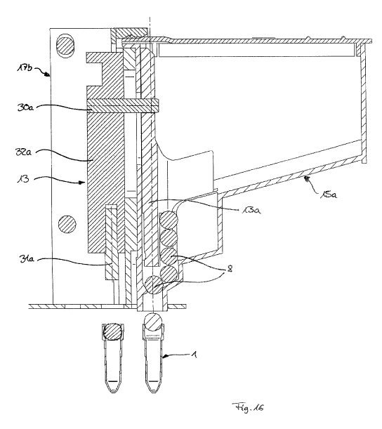
Figure 16 shows a closing unit 17b, which corresponds substantially to that of
figure 15
in terms of function, but is of simpler construction however. A (mechanical)
force
limitation unit is not provided here, rather this is achieved electronically
by a
corresponding controller of the ram drive. The ram element 31a is therefore
integrated
in the main body 32a of the ram 13 in an axially stationary manner, and the
bolt 30a for
entrainment of the ram 13a of the storage container also is not spring-
mounted. In this
case, the storage container 15a corresponds to that of figure 15.
CA 02829706 2013-09-10
. .
-15
The closing units 17, 17a, 17b and storage containers 15, 15a can be
integrated into
an automatic closing device 25, as is illustrated in figure 17. There, the
unit formed
from a closing unit 17 and storage container 15 can be displaced by a linear
drive 26
along a first axis (in the transverse direction).
The automatic closing device according to figure 17 can in turn be integrated
into a
device for carrying out a PCR process according to figure 18, in such a way
that the
closing device 25 as a whole is displaceable by a second linear drive 27 along
a
second axis (in the longitudinal direction), which is oriented perpendicularly
to the first
axis (the axis of displacement of the linear drive 26 of the closing device).
The
displaceability of the unit formed of the closing unit 17 and storage
container 15 in two
axes oriented perpendicularly to one another makes it possible to remove a
multiplicity
of housings 2 of sample containers 1, which are positioned in a number of rows
in a
total of three sample container supports 7, and to close each of said housings
with a
closing element 8. The correct placement of the closing element 8 in the
individual
housings 2 is checked here with the aid of a laser distance sensor (not
illustrated).
Figure 19, in a schematic illustration, shows the possibility of fixing the
closing
elements 8 releasably in a conveyor belt (blister tape) 28 and of positioning
said
closing elements successively over a movement of the conveyor belt 28 in the
transfer
position, from which they can then be introduced by means of a ram 13 into the
opening channel of a sample container 1. The conveyor belt 28 has a main belt
36
provided with openings arranged at regular intervals, wherein, in the region
of each of
the openings, a closing element 8 rests on one side of the main belt 26 and is
surrounded there by a retaining belt 37 and is thus held in place. The
individual closing
elements can be removed from the conveyor belt 28 through the prospective
opening
and driven into the opening channel of the sample container 1 by means of the
ram 13.