Note: Descriptions are shown in the official language in which they were submitted.
- 1 -
Device for capping a container neck
The present invention concerns a device for capping a
container neck.
The invention relates generally to caps comprising two
main components, namely an external outer cap, which is
designed to be fixed removably around the neck of a
container, notably by screwing-unscrewing, and an
internai insert, which is designed to block the neck in
sealed manner and which, during assembly of the cap, is
permanently fastened inside the outer cap.
In a field that the invention does flot concern capping
devices of this type are known in which the insert is
first added to and permanently fixed inside the outer
cap, before thereafter placing on a container neck to
be capped the combination consisting of the assembly of
this insert and this outer cap. US-A-6 044 995,
GB-A-1 316 162 and FR-A-2 219 081 provide examples of
this: in ail cases, the proposed inserts are a priori
incapable of being added to the free end of a container
neck and retained in sealed manner if the outer cap of
the device is flot conjointly present with the insert.
In contrast to what has just been described, the
invention specifically concerns caps for which the
insert is designed to be fitted to the neck
independently of the outer cap se that this insert is
advantageously placed on the neck before the outer cap
is fitted afterwards. EP-A-1 254 848 provides one
example of such a cap. EP-A-1 254 848 includes disclosure
relating to a device for capping a container neck, including
an external outer cap adapted to be removably fixed to the
CA 2829880 2018-10-17
=
- la -
exterior face of a container neck and an internai insert
adapted to plug the opening of the neck, which insert is
adapted to be fitted to the neck independently of the outer
cap and before fitting the outer cap to the neck, and which
outer cap is adapted, when it is fitted to the neck, to be
permanently fastened to the insert fitted beforehand to the
neck.
The benefit of such a cap structure is linked to
sanitary considerations: accordingly, in
EP-A-1 254 848, after a container is filled in an
aseptic filling enclosure, the insert alone can be
easily fitted, also in this aseptic enclosure, sa as to
CA 2829880 2018-10-17
- 2 -
hermetically seal the neck without biological
contamination of the content of the container, before
the container is transferred into a non-aseptic
bottling area, in which the outer cap is fitted to the
neck already plugged by the insert.
This being so, current capping devices, including that
proposed by EP-A-1 254 848, do flot provide a
satisfactory solution for situations where, when
filling the container, the exterior face of the neck
thereof is soiled by the product with which the
container is filled. Indeed, in the event of
overfilling, product overflows the neck and runs down
its exterior face. Runs can also be produced in the
event of leaks or splashes originating from the filling
system. The situation is the sanie for ail products
tending to foam up, such as beer. Moreover, for beer in
particular, the formation of foam is even intended so
that this foam occupies ail of the free volume of the
neck, above the surface of the beer, and thus expels
the air initially present. In this case, considerable
runs of foam systematically occur and therefore
significantly sou l the exterior face of the neck. The
residues of the liquid, left by these runs, often lead
to biological contamination of the neck of the
container by yeasts or the like.
The object of the present invention is to propose a
capping device of the type referred to above that makes
it possible to lirait the risk of biological
contamination of a container neck to be closed by this
capping device.
To this end, the invention consists in a device for
capping a container neck, including an external outer cap
adapted to be removably fixed to the exterior face of a
CA 2829880 2018-10-17
- 2a -
container neck and an internai insert adapted to plug the
opening of the neck, which insert is adapted to be fitted
to the neck independently of the outer cap and before
fitting the outer cap to the neck, and which outer cap is
adapted, when it is fitted to the neck, to be permanently
fastened to the insert fitted beforehand to the neck,
characterized in that the insert includes means for
retaining it on the neck adapted to connect the insert
mechanically to the neck before the outer cap is fitted
to the neck, sealing at least the exterior peripheral
surface of the free end of the neck against a cleaning
liquid applied externally to the neck.
One of the ideas on which the Invention is based is to
seek to clean the neck with an ad hoc cleaning liquid
CA 2829880 2018-10-17
=
- 3 -
after the neck has been plugged by the insert but
before fitting the outer cap around the neck. In
practice, to do this, the insert is, in accordance with
the invention, designed, during its fitting, to be
mechanically connected to the neck, in particular
sufficiently so to remain in place during application
of the cleaning liquid, typically effected by spraying,
and thus at a certain pressure, as well as during
subsequent drying, typically effected by blowing air,
and thus also at a certain pressure. If an overpressure
exists inside the neck of the container, linked notably
to the presence of a gassy product, such as beer, in
the container, the aforementioned mechanical connection
is made sufficient to resist this overpressure, at
least for the time taken to clean the neck of the
container. Moreover, the insert of the device of the
invention effectively seals the free end of the neck
fraie the outside: in this way, the cleaning liquid does
flot insinuate itself between the insert and the free
end of the neck, notably on the edge of the neck, to
prevent traces of this cleaning liquid thereafter
remaining on the edge and then being ingested by the
user, notably through mixing with the product poured
via the neck of the container. Thus after filling a
container and capping the neck with the insert of the
device of the invention, most of the exterior face of
the neck, in particular the main part of the neck where
the outer cap will be removably fixed, typically by
screwing-unscrewing, may be cleaned effectively and
rapidly, without running the risk that, during the
cleaning operations as such, the insert is moved or
raised relative to the neck, then allowing the cleaning
liquid to pass toward the interior of the container.
Advantageous additional features of the capping device
of the invention, taken separately or in ail
technically possible combinations, are provided as follows:
CA 2829880 2018-10-17
- 3a -
In some embodiments the outer cap includes:
a substantially tubular skirt defining a central axis
and having means for removably fixing the skirt to the
exterior face of the neck, and
an end wall extending across one axial end of the skirt
and against which at least part of the capping face of the
body of the insert bears during fitting of the outer cap to
the neck,
wherein the skirt has an internai retaining raised
pattern adapted, after the outer cap is fitted to the neck,
to retain the insert axially in a direction away from the
end wall by engaging with an exterior peripheral part of the
capping face of the body of the insert.
In some embodiments the retaining raised pattern includes
tabs projecting from the interior face of the skirt, and
wherein the skirt includes openings situated in the direction
of the axis of the skirt between the tabs and the end wall,
and wherein the openings open in a direction transverse to
the axis.
In some embodiments an interior of the skirt defines a groove
for receiving the insert that runs in a continuous or
interrupted manner around the periphery of the skirt, the
axial end of the groove at the opposite end of the end wall
includes a shoulder projecting toward the interior of the
skirt to form said retaining raised pattern.
In some embodiments an internai of the skirt includes,
axially between the retaining raised pattern and the
removable fixing means, a surface adapted to bear against
the external face of the exterior sealing lip.
In some embodiments the end wall of the outer cap and the
face of the body of the insert on the opposite side of the
CA 2829880 2018-10-17
- 3b -
capping face of the body include raised patterns adapted,
after the outer cap is fitted to the neck, to connect the
outer cap and the insert either rotatably about the axis of
the skirt or in translation along the axis.
In some embodiments the end wall of the outer cap and the
body of the insert are connected by adhesion or welding.
In some embodiments the end wall of the outer cap and the
body of the insert are connected by laser welding.
In some embodiments the insert and the outer cap are fastened
together by laser welding.
In some embodiments the insert and the outer cap are fastened
together using only laser welding.
In some embodiments the insert includes an oxygen fixing
layer either within the thickness of the body of the insert
or fixed to the capping face of the body.
CA 2829880 2018-10-17
CA 02829880 2013-09-06
- 4 -
The invention will be better understood on reading the
following description given by way of example only and
with reference to the drawings, in which:
- Figure 1 is an exploded view of a capping device of a
first embodiment of the invention associated with a
container neck to be closed by this device, the left-
hand half of this figure being an elevation view of
the device and the neck while the right-hand half is
a longitudinal section through these elements;
- Figure 2 is a view to a larger scale of the ringed
area II in Figure 1;
- Figure 3 is a view in longitudinal section of a
component of the device from Figure 1, fitted to the
neck, thus showing a step of capping of this neck by
the device;
- Figure 4 is a view to a larger scale of the ringed
area IV in Figure 3;
- Figure 5 is a view analogous to Figure 3, showing a
subsequent step of capping the neck of the container
with the device from Figure I;
- Figure 6 is a view to a larger scale of the ringed
area VI in Figure 5;
- Figure 7 is a view analogous to Figure 1, showing a
capping device of a second embodiment of the
invention;
- Figure 8 is a view analogous to Figure 5 for the
Figure 7 embodiment; and
- Figure 9 is a view to a larger scale of the ringed
area IX in Figure 8.
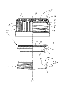
In Figures 1 to 6 there is represented a device 1 for
capping a neck 2 of a container.
In practice, the neck 2 is either made in one piece
with the rest of the container, notably when the latter
is a glass or plastic material bottle, or adapted to be
permanently fastened to a wall of the container, in an
opening passing through that wall.
= CA 02829880 2013-09-06
- 5 -
The neck 2 has a globally tubular shape, with a central
longitudinal axis X-X. For convenience, the remainder
of the description is oriented taking the terms "upper"
and "top" as corresponding to a direction globally
parallel to the axis X-X and extending from the body of
the container toward the free end of its neck 2, i.e.
an upward direction in the figures, while the terms
"lower- and "bottant- correspond to an opposite
direction.
The neck 2 includes a globally cylindrical body 3 with
a circular base and axis X-X. At its top end 4, this
body 3 delimits an edge 4A at the level of which the
product contained in the container is intended to be
poured out. The exterior face 3A of the body 3
includes, successively from top to bottom, the exterior
surface 3A1 of the end 4 and the exterior surface 3A2
of the main part of the body 3, which is provided with
a helical thread 5 projecting radially outward.
The device 1 primarily comprises two components, namely
an external outer cap 10 and an internai insert 20.
As can be seen clearly in Figure 1, the outer cap 10
has a globally tubular shape, the central longitudinal
axis of which coincides with the axis X-X of the neck 2
when the device 1 is fitted to the neck (Figure 5). The
outer cap 10 is open at its lower end and closed at its
upper end by a plane end wall 11 at the exterior
periphery of which a tubular skirt 12 centred on the
axis X-X extends downward. The main part of the
interior face of the skirt 12 is provided with a
screwthread 13 projecting radially inward and
complementary to the exterior screwthread 5 of the neck
2, thus enabling the outer cap 10 to be screwed onto
and unscrewed from the neck. To facilitate grasping and
turning this outer cap, the exterior face of the skirt
12 is provided with projecting ribs 14, which extend
lengthwise parallel to the axis X-X and are distributed
CA 02829880 2013-09-06
- 6 -
in a substantially uniform manner around the exterior
periphery of the skirt, as can be seen clearly in
Figure 1. The embodiment of these ribs 14 shown in the
figures is merely illustrative and is flot limiting on
the invention in that diverse other shapes for
facilitating turning of the outer cap by a user may be
envisaged.
In its upper end part, the skirt 12 is internally
provided with a plurality of tabs 15 ail of which are
globally situated in the same plane perpendicular to
the axis X-X, being distributed in a substantially
regular manner along the interior periphery of the
skirt. In practice, and as in the embodiment shown in
the figures, the aforementioned plane is situated,
along the axis X-X, more or less half way between the
end wall 11 and the axial level of the upper end of the
thread 13. Each tab 15 projects radially inward front
the interior face of the skirt 12. Thus each tab 15
delimits, fading the end wall 11, a substantially plane
upper surface 15A, the surfaces 15A of the various tabs
15 ail lying in a plane perpendicular to the axis X-X.
Also in its upper end part, the skirt 12 delimits a
plurality of openings 16 ail of which are globally
situated in the same plane perpendicular to the axis X-
X, being distributed in a substantially regular manner
Around the periphery of the skirt. The openings 16
occupy the same peripheral portions of the skirt 12 as
the tabs 15, being situated, along the axis X-X,
between the plane containing the tabs 15 and the end
wall 11. In other words, each of the openings 16 thus
passes completely through the wall of the skirt 12,
opening onto one of the tabs 15 inside the outer cap
10. Around the periphery of the skirt 12, the wall of
the latter between two successive openings 16 is solid,
having internally no tabs similar to the tabs 15, more
generally being free of any raised pattern projecting
radially inward. The benefit of the tabs 15 and the
CA 02829880 2013-09-06
=
- 7 -
openings 16 will become apparent later.
The upper end part of the skirt 12 is advantageously
provided externally with projecting ribs 17 that extend
lengthwise between the upper end of the exterior face
of the skirt 12, in other words the axial level of the
end wall 11, and the axial level at which are situated
the upper ends of the ribs 14 present in the main part
of the exterior face of the skirt. Around the periphery
of the skirt, these ribs 17 can obviously not be
present in the portions occupied by the openings 16: in
fact, each of the ribs 17 is systematically provided
between two successive openings 16, as can be seen
clearly in Figure 1. Moreover, the width of the ribs
17, i.e. their dimension in the peripheral direction of
the skirt 12, is greater than that of the ribs 14. As a
result of this these ribs 17 confer on the outer cap 10
a singular exterior aesthetic, redolent of the usual
exterior shape of beer bottle crown outer caps. The
ribs 17 also have the benefit of stiffening and
mechanically strengthening the portions of the wall of
the skirt 12 successively separating the openings 16.
This mechanical strengthening will be exploited during
assembly of the device 1, as explained later, as well
as on removal of the outer cap 10 from the mould when
the latter is made from a moulded plastic material.
Considering the insert 20 in more detail now, it is
seen that the latter comprises a main body 21 having a
globally disc-1ike shape, centred on an axis which,
when the device 1 is assembled and fitted to the neck
2, substantially coincides with the axis X-X. As can be
seen clearly in Figure 2, the body 21 is provided on
its lower face 21A with two sealing lips 22 and 23
which have respective annular shapes, coaxial with each
other and centred on the axis X-X, and projecting
axially from the face 21A of the body 21. For reasons
explained later, the external face 23A of the lip 23
has a radially projecting raised pattern which, in the
= CA 02829880 2013-09-06
- 8 -
embodiment shown in the figures, consists of a boss
23A1 with a rounded top. Moreover, between these lips
22 and 23 in a direction radial with respect to the
axis X-X, the lower face 21A of the body 21 is provided
with a projecting heel 24 that is arranged in the
connecting area between the face 21A and the internal
face 22A of the lip 22 radially farther from the axis
X-X than the lip 23. Accordingly, as can be seen
clearly in Figure 2, a free space 25 is provided
axially below the face 21A of the body 21, radially
between the heel 24 and the connecting area between
this face 21A and the external face 23A of the lip 23.
The benefit of the technical aspects of the insert 20
that have just been described will become clear
shortly, on describing an example of the installation
of the device 1 on the container neck 2.
Accordingly, initially, it is considered that the
container, the neck 2 of which is represented in the
figures, has just been filled with a product, where
appropriate a foaming product, such as beer. For
diverse reasons it is found that this filling
operation, where applicable with the formation of foam,
very often leads to soiling of the exterior face 3A of
the neck 2, in particular to soiling of the threaded
surface 3A2 of this face 3A.
Independently of the outer cap 10, the insert 20 is
then placed on the neck 2, being both aligned on the
axis X-X and placed across the top end 4 of the neck 2
in order to block the central opening of the body 3 of
the neck: the insert 20 is then in the configuration
represented in Figure 3. To be more precise, the body
21 of the insert 20 transversely covers the end 4 of
the neck 2, with its lower face 21A blocking the
opening of the neck. In the direction of the axis X-X,
the body 21 occupies a position in which the heel 24
bears axially in sealed manner against the edge 4A of
= CA 02829880 2013-09-06
- 9 -
the neck 2, to be more precise against an exterior
peripheral part 4A1 of this edge, as can be seen
clearly in Figure 4. At the same time, the lips 22 and
23 are pressed in sealed manner against the exterior
face 3A and the interior face 3B, respectively, of the
body 3 of the neck 2: given the shapes and the
dimensions of the lips 22 and 23, the internai face 22A
of the lip 22 bears in sealed manner against the
exterior surface 3A1 of the end 4 of the neck 2, while
the boss 23A1 on the external face 23A of the lip 23
bears in sealed manner against the interior surface of
the main part of the body 3 of the neck 2. Also at this
same time, the free space 25 is provided in vertical
axial alignment with the interior peripheral part 4A2
of the edge 4, as can be seen clearly in Figure 4.
By virtue of their flexible deformation, resulting from
their interference with the body 3 of the neck 2, the
lips 22 and 23, in addition to their sealing action
described above, provide a mechanical action of
retention of the insert 20 relative to the neck 2 once
this insert is fitted to the neck in this way. Indeed,
in that, given their dimensions relative to the body 3
of the neck 2, each of these lips 22 and 23 is
partially deformed relative to the body 21, tending to
revert elastically to their initial configuration,
typically their configuration on removal from the
mould, thus procuring an effect of mechanical
connection with the body 3 of the neck 2, notably by
friction, wedging, adhesion, etc. In practice, given
their respective dimensions, it is the interior lip 23
that produces the greater part of the aforementioned
mechanical connection effect, by virtue of friction of
its boss 23A1 against the interior face 3B of the body
3 of the neck 2, this friction producing a radial
loading of the lip 23 against the interior of the neck
2, the intensity of which is directly dependent on the
designed interference between the maximum outside
diameter of the lip 23, i.e. its diameter at the axial
= CA 02829880 2013-09-06
- 10 -
level of the boss 23A1, and the inside diameter of the
body 3 of the neck 2. Moreover, it is clear that one of
the benefits of the free space 25 is to allow the lip
23 to retain its elasticity over time, i.e. following
repeated opening and closing of the device 1, and thus
to retain its sealing performance in the long term.
The benefit of the mechanical connection referred to
above is that, in the next step of the capping process,
a cleaning liquid is applied to the neck 2, in
particular by being sprayed onto this neck as indicated
by the arrows F in Figure 3, sa as to clean off soiling
present on the exterior face 3A of the body 3, notably
the threaded surface 3A2 left uncovered by the lip 22.
Accordingly, the aforementioned cleaning liquid can be
applied with a certain pressure, strengthening its
cleaning efficacy, with no risk of moving or lifting
the insert 20 retained on the neck. Similarly,
application of the cleaning liquid is advantageously
followed by a step of drying this liquid, typically by
blowing air, where appropriate compressed air. Again,
this drying step is carried out with no risk of moving
or lifting the insert 20 relative to the neck. More
generally, these cleaning steps are thus carried out
without the cleaning fluid being able to insinuate
itself into the neck 2, this liquid being stopped by
the seal produced by the lip 22.
It will be noted that, in the situation where an
overpressure exists inside the neck 2, as is the case
when the container is filled with beer or, more
generally, a gassy product, the mechanical retention
effect and the sealing effect that are produced by the
sealing lip 23 can easily be such that the insert 20
resists the overpressure, without moving, at least for
a sufficient time for carrying out the cleaning steps.
As for the mechanical retention effect and the sealing
effect, which are produced by the lip 22, they are
advantageously strengthened by this overpressure
CA 02829880 2013-09-06
- 11 -
because it tends to cause the body 21 to bow slightly
toward the outside, which, through a lever effect,
presses the internai face 22A of the lip 22 more
strongly against the surface 3A1 of the end 4 of the
neck 2.
The capping of the neck 2 thereafter continues with
fitting the outer cap 10. As represented in Figures 5
and 6, the outer cap 10 is fitted around the neck 2 on
which the insert 20 is already installed, being centred
on the axis X-X and being driven downward until its end
wall 11 cornes to bear against the upper face 21B of the
body 21 of the insert 20. In so doing, the internai
thread 13 of the outer cap is engaged with the external
thread 5 of the neck 2.
As explained in detail hereinafter, this fitting of the
outer cap 10 causes the outer cap and the insert 20 to
be fastened together. The body 21 of the insert is
designed with dimensions such that its exterior
periphery cooperates through complementary shapes and
interference with the tabs 15 and the openings 16 of
the outer cap 10. Ta be more precise, on the one hand,
the body 21 has, at least at its exterior periphery, a
thickness, i.e. a dimension along the axis X-X,
substantially equal to or slightly less than the axial
separation between the plane containing the upper
surfaces 15A of the tabs 15 and the lower face of the
end wall 11. On the other hand, the lower face 21A of
the body 21 includes a substantially plane exterior
peripheral surface 21A1 that connects the external face
of the lip 22 and the peripheral edge surface at the
end of the body 21, and that is situated relative to
the axis X-X at a distance substantially identical to
that between that axis and the surfaces 15A of the tabs
15. In other words, the exterior peripheral surface
21A1 of the lower face 21A of the body 21 forms a
shoulder that is complementary to the tabs 15, thereby
enabling the latter to retain the insert 20 in the
CA 02829880 2013-09-06
- 12 -
axially downward direction once the end wall 11 of the
outer cap 10 has been brought ta bear against the upper
face 21B of the body 21, as can be seen clearly in
Figure 6. In practice it is clear that, for the tabs 15
ta be located axially below the body 21 and for the
exterior peripheral surface 21A1 of its lower face 21A
ta bear down on them, the exterior periphery of the
body 21 and the upper end part of the skirt 12 are
subjected ta elastic deformation stresses, it being
noted that the openings 16 facilitate and accommodate
such deformation, preventing damage to the insert or
the outer cap.
Once the outer cap 10 has been fitted in this way, the
insert 20 is permanently fastened ta the outer cap, in
the sense that, on subsequent opening of the device 1,
i.e. when the user unscrews the outer cap 10, the
latter entrains the insert 20 with it, at least in
translation in the direction of the axis X-X. In other
words, the insert 20 is trapped inside the outer cap
10, through the exterior periphery of its body 21
bearing axially downwards on the tabs 15.
The skirt 12 is advantageously sized sa that, when the
insert 20 is fitted inside the outer cap 10 in this
way, in its axial part situated below the tabs 15 and
above the thread 13, its internal face bears radially
against the external face 22B of the lip 22. In other
words, axially between the plane in which the tabs 15
are situated and the upper end of the thread 13, the
skirt has internally a surface 18 the diameter of which
interferes with the outside diameter of the lip 22. In
this way, when the outer cap 10 is screwed all the way
onto the neck 2, the surface 18 reinforces the bearing
of the lip 22 against the external face 3A of the neck
and thus enhances the sealing performance of this lip.
It will be noted that, on subsequently opening the
device 1, the fastening together of the insert 20 and
= CA 02829880 2013-09-06
- 13 -
the outer cap 10 is, so to speak, stronger than the
mechanical connection between the insert 20 and the
neck 2, in the sense that the force retaining the
insert 20 on the neck 2, which was exploited during the
operations of cleaning the neck 2, described with
reference to Figures 3 and 4, is overcome by the
fastening together of the insert and the outer cap
obtained on fitting the outer cap. The ribs 17
advantageously increase the resistance to deformation
of the upper end part of the skirt 12 to hold the
insert 20 outer captive on opening the device 1.
In a variant of the insert 20, not shown, the exterior
periphery of its body 21 may be crenelated, i.e., at
its exterior periphery, the body 21 may be provided
with a plurality of tongues projecting radially inward
that are sized and angularly positioned so that each
engages radially in one of the openings 16 of the skirt
12. Clearly this solution, more complicated in teLms of
the production of the insert 20, allows radial
enlargement of the contact interface between the
surfaces 15A of the tabs 15 and the lower face 21A of
the insert 20, since the aforementioned projecting
tongues can be designed to extend deeper in the
openings 16, in the direction of the exterior face of
the skirt 12, than can the circuler transverse profile
exterior periphery of the body 21 of the insert 20
considered in Figures 1 to 6.
By way of an optional advantageous feature, present in
the embodiment of Figures 1 to 6, the insert 20 is
designed to limit the passage of oxygen through it. To
be more precise, in the embodiment considered in
Figures 1 to 6, the body 21 of the insert 20 is
provided with an oxygen-sensitive layer 26 within the
thickness of this body. In practice, and in a manner
that is known in itself, the material constituting the
layer 26 forms an oxygen barrier or traps oxygen by
fixing it. To arrive at this embodiment a plurality of
CA 02829880 2013-09-06
- 14 -
manufacturing techniques may be envisaged: a first
solution consists in moulding the body 21 around the
layer 26 moulded independently beforehand. Another
solution consists in carrying out conjointly the
moulding of the body 21 and the moulding of the layer
26, typically by dual-injection of plastic materials.
In a variant that is flot shown, rather than being
provided within the thickness of the body 21, the layer
26 may be fixed against the lower face 21A of the body
21, inside the lip 23: this fixing may be obtained by
dual-injection of plastic materials or by adhesive
bonding. Similarly, another alternative that is flot
shown consists in substituting for the layer 26 the
addition of oxygen-sensitive agents incorporated
directly into the plastic material of the body 21,
before moulding the body.
In Figures 7 to 9 there is represented a capping device
100 constituting an alternative embodiment of the
device 1. This device 100 includes a outer cap 110 and
an insert 120 functionally similar to the outer cap 10
and the insert 20 of the device 1. As explained in more
detail later, the device 100 differs from the device 1
essentially in how the outer cap 110 and the insert 120
are fastened together on fitting the outer cap 110. The
insert 120 also differs from the insert 20 through the
absence of an oxygen-sensitive layer, such as the layer
26. Accordingly, the outer cap 110 comprises an end
wall 111 and a skirt 112 with a thread 113, ribs 114
and a lower surface 118 which are functionally similar
to the end wall 11, skirt 12, thread 13, ribs 14 and
surface 18 of the outer cap 10. Similarly, the insert
120 comprises a body 121 with an exterior sealing lip
122, an interior sealing lip 123 and a heel 124
associated with a free space 125 which are respectively
similar to the body 21, lips 22 and 23, heel 24 and
space 25 of the insert 20.
Differing in this respect from the outer cap 10, the
CA 02829880 2013-09-06
- 15 -
upper end part of the skirt 112 of the outer cap 110 is
solid ail around its periphery, has a substantially
smooth exterior face and is provided internally with a
groove 116 that runs around ail of the interior
periphery of the skirt, in the connecting area between
this skirt and the end wall 111. This groove 116 is
sized to receive the exterior periphery of the body 121
when fitting the outer cap 110 over the insert 120
previously fitted to the neck 2, as represented in
Figures 8 and 9. The groove 116 is substantially
complementary to the exterior periphery of the body 21
and is flanked on its lower axial side by a shoulder
115 projecting radially toward the inside of the skirt
112. Thus, at the axial level of its lower side, the
groove 116 opens onto the upper surface 115A of the
shoulder 115, on which the exterior peripheral surface
121A1 of the lower face 121A of the body 121 bears
down, as can be seen clearly in Figure 9. Accordingly,
the cooperation between the exterior periphery of the
body 121 of the insert 120 and the groove 115 of the
outer cap 110 is similar to that between the exterior
periphery of the body 21 of the insert 20 and the tabs
15 of the outer cap 10. However, it will be noted that,
in practice, ail other things being equal, the radial
extent of the upper surfaces 15A of the tabs 15 may
advantageously be made greater than the radial
dimension of the shouldered surface 115A flanking the
groove 116, for reasons linked to the manufacture of
the outer caps 10 and 110. When moulding the outer cap
110, it remains difficult to achleve a large radial
extent of the shouldered surface 115A, given mould
extraction constraints. In this context, recourse to an
eclipsable moulding cote is advantageously preferred.
In a variant of the outer cap 110 that is flot shown its
groove 116 may be regularly interrupted Around the
periphery of the skirt 112, which amounts to saying
that the groove 116 from Figures 7 to 9 is replaced by
a plurality of notches, distributed along the interior
CA 02829880 2013-09-06
=
- 16 -
periphery of the skirt 112, the shoulder 115 then
remaining in its uninterrupted form along the interior
periphery of the skirt 112 or being interrupted like
the groove.
Various adaptations and variants of the devices 1 and
100 described until now may be envisaged. For example:
- rather than fastening together the outer cap 10 or
110 and the insert 20 or 120 by cooperation between
the exterior periphery of the insert and the skirt of
the outer cap, this fastening may be obtained by
cooperation between dedicated features of the end
wall of the outer cap and complementary dedicated
features of the upper face of the body of the insert;
for example, complementary clipping tongues may be
provided projecting from the central region of the
end wall of the outer cap and the central region of
the upper face of the body of the insert; compared to
the embodiments shown in the figures, this solution
may lead to a capping device that is slightly more
bulky in the direction of the axis X-X;
- in addition to, or instead of, the mechanical
fastening together of the outer cap and the insert
described until now, other modes of fastening may be
envisaged, notably by adhesive bonding and/or by
welding; one particularly advantageous option is for
the insert, placed on the container neck before the
latter is cleaned, and the outer cap, which is put
onto the container neck after it is cleaned and with
the insert left in place thereon, to be welded to
each other, in particular directly to each other, by
laser welding, such laser welding being carried out
by ad hoc means known in themselves;
- in addition to the diverse fastening solutions
between the outer cap and the insert referred to
above, additional features may be provided for
rotationally connecting the outer cap and the insert;
returning to the embodiment of Figures 1 to 6, for
example, the upper face 2113 of the body 21 of the
CA 02829880 2013-09-06
- 17 -
insert 20 and the lower face of the end wall 11 may
be at least partly striated in complementary manner
in order to prevent rotation of the insert 20
relative to the outer cap 10, as well as being
retained in the axially downward direction by the
tabs 15; the outer captive retention of the insert 20
inside the outer cap 10 during manipulation thereof
to open and, where applicable, reclose the device 1
is strengthened by this;
- embodiments other than the threads 13 or 113 may be
envisaged for the removable fixing of the skirt 12 or
112 to the neck 2; for example, this skirt may be
provided internally with one or more clips designed
to be wedged onto an exterior raised pattern
projecting from the neck; and/or
- means for making evident the first opening of the
device 1 or 100 may be added, typically in the form
of a tamper-evident strip or a tongue which, on first
opening of the device, is separated from the skirt 12
or 112.