Note: Descriptions are shown in the official language in which they were submitted.
CA 02829900 2013-10-15
PATENT
Docket No.: 125/0003R
SINUOUS TRAFFIC LINE
FIELD OF THE INVENTION
100011 This invention relates to systems to facilitate the traffic
safety and
more particularly to the arrangement and disposition of traffic lines.
BACKGROUND OF THE INVENTION
[0002] Traffic lines are an accepted device in the field of traffic
safety. The
earliest traffic lines were put into use by Edward N. Hines on Trenton's River
Road in
Wayne County, Michigan. Later refinements led to single and double lines,
broken lines
located in the center of the roadway and along the edges.
100031 Traffic lines can be painted with a basic permanent paint that is
optimally
visible only under the best illumination. Given that roadways are travelled by
day and
night, in conditions of clear weather, fog, snow, sleet, smoke or other visual
impairments.
Under these circumstances, the paint can become invisible and increase the
risks to the
traveler. Furthermore, even the stoutest paint can be rubbed off the road
surface by plow
trucks, sand and other causes. Roadway engineers have determined that
thermoplastic
paints last longer than common paint and that small glass beads added to the
mixture
create a reflective surface that increases visibility under inclement
conditions and at
night. Thermoplastic traffic paint is generally applied in two coats, each of
60 mil
thickness. The colors used are white and yellow. The thermoplastic paint is
applied hot
by spraying of extruded as a ribbon and is 4 inches in width. The glass beads
are added
while the mixture is still molten hot. The mixture starts as a homogenous dry
mix of
binder resins, plasticizers, glass beads (or similar material bead), pigments
and fillers.
The mixture is heated to approximately 400 degrees Fahrenheit and placed into
the
dispenser, which is mounted on a vehicle or a small "walk behind" manually
operated
device. The lines can be uniform on their upper surface or embossed with
diamond or
1
CA 02829900 2013-10-15
PATENT
Docket No.: 125/0003R
other patterns to increase reflectivity. The application of a binding agent
prior to the
application of the traffic line material can improve the longevity of the
traffic lines.
[0004] The visibility of traffic lines remains a problem for travelers.
The lines
tend to be elongated ribbons of reflective material when viewed from the
driver's seat.
Over time, the traveler's visual acuity can degrade from fatigue and the
homogeneity of
the elongated lines lose their relevance, increasing the risk to the driver.
Fig. 1 is a view
of a roadway 100 provided with traffic lines 102 and a truck 104 that is
driving with the
assistance of its headlights 106 and their cast beams 108. The extent of the
driver's
optimal visibility is represented by broken line 110. The lines 102 are evenly
spaced and
stretch off into the gloom and darkness, disappearing beyond the optimal
visibility extent
110. It would be desirable to provide a traffic line that is reflective and
constructed and
arranged to be visually stimulating and maintain the interest of the driver,
thereby
increasing highway safety.
SUMMARY OF THE INVENTION
[0005] This invention overcomes the disadvantages of the prior art by
providing a
sinusoidal traffic line that has scalloped edges to form a sine wave that
increases
visibility under conditions of reduced visibility, for example, during rain,
night or fog.
The traffic line is formed of a pre-cut ribbon or applied traffic line
material (e.g., sprayed
thermoplastic material). The traffic lines have a wavy left edge and a wavy
right edge.
The edges are formed in a regular pattern, having a regular amplitude and
wavelength
relative to a directional vector along the axis of the traffic line. In an
embodiment, a
pattern of the wavy left edge corresponds to and is identical to a pattern of
the wavy right
edge. The line is reflective of light and can be formed of a thermoplastic
mixture to
which a quantity of glass beads has been added. The sinusoidal traffic lines
have a
regular lateral amplitude of approximately 1 to 2 inches at a wavelength of
approximately
4 to 6 inches. The longitudinal wavelength and lateral amplitude can be varied
greater
and lesser depending on the prevailing travel speed of the underlying road. In
another
2
CA 02829900 2013-10-15
PATENT
Docket No.: 125/0003R
embodiment, the patterns of the outer edges are arranged in an opposite
arrangement such
that they converge and diverge, having a regular lateral amplitude of
approximately 2 to
4 inches. The upper surface of the traffic line can be embossed by an embossed
device so
as to create a regular pattern and increase reflectivity. In an embodiment, an
embossed
pattern is a diamond pattern.
[0006] The sinusoidal traffic line is created by applying a pre-cut
ribbon having a
regular pattern or by applying traffic line material via an applicator head
and nozzle. An
applicator device can be a walk-along machine or a vehicle mounted device. A
mixture
of traffic line material is placed into the applicator device and is pre-
heated.
Thermoplastic traffic paint is pre-heated to approximately 400 degrees
Fahrenheit. A
pre-determined quantity of glass beads is added to the mixture and pressure is
applied to
carry the mixture through a feed line to an applicator head that is provided
with a nozzle.
The applicator head is set at a pre-determined elevation. The applicator head
is moved
laterally relative to the direction of travel and the applicator device
forward travel rate is
set such that lines having the desired amplitude and wavelength are created.
The
applicator device can be provided with an embossing device to create a regular
pattern on
the upper line surface (i.e., a diamond pattern) to increase reflectivity. In
other
embodiments, the nozzle can have variable geometry walls to create the
sinusoidal line, a
rotatable off-center nozzle head or a swinging nozzle head.
BRIEF DESCRIPTION OF THE DRAWINGS
[0007] The invention description below refers to the accompanying
drawings, of
which:
[0008] Fig. 1, already described, is a view of a vehicle traveling along
a road way
under reduced visibility conditions, according to the prior art;
[0009] Fig. 2 is a view of a portion of an illustrative traffic line,
according to an
embodiment;
[0010] Fig. 3 is a view of a portion of an illustrative traffic line,
according to an
alternate embodiment;
3
CA 02829900 2013-10-15
PATENT
Docket No.: 125/0003R
[0011] Fig. 4 is a view of a vehicle traveling along a road way under
reduced
visibility, according to the illustrative embodiment;
[0012] Fig. 5 is a view of a portion of an applicator for applying
sinusoidal traffic
lines to a road way surface, according to an illustrative embodiment;
[0013] Fig. 5A is a view of a portion of an applicator having a variable
geometry
for applying sinusoidal traffic lines to a road way surface, according to an
illustrative
embodiment; and
[0014] Fig. 6 is a schematic diagram of the steps in the application of
material to
create sinusoidal traffic lines, according to the illustrative embodiment.
DETAILED DESCRIPTION
[0015] A portion of an illustrative sinusoidal traffic line 200 is shown
in Fig. 2
and is defined as resembling a sine wave in shape. The sinusoidal lines are
formed by
"scalloping" the edges, that is to say, by omitting material by removal or non-
application.
LE is the axis of the left side edge of a traffic line and RE is the axis of
the right side
edge of a traffic line, relative to the center axis AA of the traffic line.
The scalloping can
be created by omitting material from the lines during their application, so
that there are
areas 202 of omitted material. The scalloping pattern is regular and is
constructed and
arranged as a sine wave relative to the vector AA of the line. In an
embodiment, a
pattern of the wavy left edge corresponds to and is identical to a pattern of
the wavy right
edge and is in phase. The inner limit axis IA of the sine-wave shaped outer
edge line is
proportionate and congruent to the outer left side edge LE. The shape of the
outer line is
comprised of "crests" 208 and "troughs" 210.
[0016] The amplitude AL of the sine wave shaped edge, the distance
between the
illustrative left side edge axis LE and the inner limit axis is approximately
1-2 inches.
The wavelength of the sine wave shaped edge, that being the distance between
respective
adjacent centers of troughs 210 and/or adjacent centers of crests 208 is
approximately 4-6
inches. It is expressly contemplated that the amplitude can be arranged to be
greater or
lesser as desired by the engineer, based on the conditions of the roadway and
speed of
4
CA 02829900 2013-10-15
PATENT
Docket No.: 125/0003R
vehicles upon it. While the omission of material from the line narrows the
actual width
WL of the line, the apparent line width WL is approximately 4 inches, the
distance from
the left side edge axis LE to the right side edge axis RE. The line 200 is
constructed and
arranged so that the sine-wave shape of the left edge and the shape of the
right side are
aligned and synchronized.
[0017] The omission of the material to create the sinusoidal line can be
accomplished by a mechanism constructed and arranged to induce a sinusoidal
movement
to produce a line having the desired amplitude AL and wavelength FL or by
providing a
ready made, formed ribbon that is pre-cut in a sinusoidal pattern. The
omission of
material to create the sinusoidal lines can reduce the overall material
requirements for
creating the line by approximately 20-30 percent, greatly reducing road costs
at creation
and maintenance. The longitudinal wavelength and lateral amplitude can be
varied
greater and lesser depending on the prevailing travel speed of the underlying
road.
[0018] Fig. 3 depicts a sinusoidal traffic line 300 that is constructed
and arranged
so that the crests 306 and troughs 308 are counterpoised and asynchronous,
according to
another embodiment. The shapes of the lines are formed and arranged as set
forth above,
and include regions 302 of omitted material. This creates a series of
relatively wide and
narrow segments. The sinusoidal wavy lines are 180 degrees out of phase and
have
opposing amplitudes. The overall visual effect to the traveler of synchronous
and
asynchronous lines when viewed at a distance of approximately 10 feet at a
relatively low
angle of 2-3 degrees is that the line is not scalloped. Therefore, travelers
would not be
upset by the scalloping. The sine-shaped waves are more visible than the lines
in the
prior art because the scalloped edges create small areas of black between the
crests and
troughs and an enhancement of the reflective areas of the line. This makes the
lines
appear to be relatively "brighter".
[0019] Fig. 4 shows a segment of a roadway 400 provided with sinusoidal
traffic
lines 401 is traveled by a vehicle 402 that is moving along the axis of travel
AT. The
truck's headlights 404 cast beams 406 that illuminate the roadway 400. The
troughs 420
and crests 422 appear bright against the intervening omitted areas 424. The
visual effect
CA 02829900 2013-10-15
PATENT
Docket No.: 125/0003R
to the vehicle driver (not shown) presents a set of traffic lines that are
relatively brighter
than conventional parallel lines.
[0020] A portion of a spray applicator 500 for creating the sinusoidal
traffic line
is shown in Fig. 5. The applicator can be vehicle mounted device or part of a
walk-
behind manually operated paint device. The applicator head 502 is provided
with a feed
line 504 that delivers the pressurized, heated and mixed paint solution from
the source to
the applicator head 502. The applicator head is selectively motivated back and
forth in a
lateral orientation by a drive shaft 506 or similar device that is motor-
driven and moves
the head 502 back and forth a distance equal to the designated amplitude of
the line AL
and at a rate that creates the desired wavelength of the line FL as the
applicator 500
travels along the axis of the line AA at a pre-determined rate of travel. The
pressurized,
heated and mixed solution is dispersed through the spray nozzle 508 at the
desired width
and is arranged to travel at an elevation above the road to produce a line of
the desired
thickness.
[0021] An applicator head 502 is depicted with a variable geometry nozzle
head
550 in Fig. 5A. The nozzle head 550 can be provided with moveable outer walls
552,
554 that are actuated by a motor (not shown) that can cause the paint spray
stream 556 to
be moved so that the line 560 formed is sinusoidal relative to the axis of
travel AT. In a
further embodiment, the nozzle head 550 can be formed to be off-center in its
orientation
relative to the central vertical axis CVA and rotatable, so that its spray
generates the
desired sinusoidal line. In another embodiment, the nozzle is constructed and
arranged to
swing from side-to-side along the lateral head axis LHA to move the spray
stream 556
from side-to-side so as to form the sinusoidal line as the spraying device
travels along the
axis of travel AT.
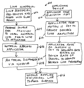
[0022] The control process 600 of applying traffic line material to create
sinusoidal traffic lines is set forth in Fig. 6. The line material ingredients
are mixed in
their appropriate quantities and are subjected to heating. When the mixture is
sufficiently
heated, glass beads are added to the mixture 602. A pressure source, for
example, an air
compressor, adds pressure to the heated material and impels a portion of the
material into
6
CA 02829900 2013-10-15
PATENT
Docket No.: 125/0003R
the feed line 604. The feed line carries the material from the source to the
applicator 606.
The material is then dispersed through the nozzle, located in the applicator
606. The
applicator head is arranged for dispersing the line material by first setting
the elevation of
the head relative to the roadway, so that the application is optimal for the
circumstances
610. The applicator is then adjusted so that its distance of lateral travel
will disperse the
material in lines having the desired line amplitude 612. The applicator rate
of motion is
then set so that the speed of the device will create lines of the desired
wavelength by
coordinating the forward motion of the device with the lateral motion of the
applicator
head 614. The applicator nozzle, set at the desired elevation and having the
desired
lateral and forward motion to disperse the lines, can begin applying the
material 616. In
another embodiment having lines as set forth in Fig. 3, the applicator can be
provided
with more than one nozzle, each having its own motion system, to create lines
having
relatively "fat" and "thin" sections.
[00231 The
foregoing has been a detailed description of illustrative embodiments
of the invention. Various modifications and additions can be made without
departing
from the spirit and scope of this invention. Features of each of the various
embodiments
described above may be combined with features of other described embodiments
as
appropriate in order to provide a multiplicity of feature combinations in
associated new
embodiments. as used herein the directional terms, such as, but not limited
to, "up" and
"down", "top" and "bottom", "inside" and "outer", "front" and "back", "inner
and
"outer", "interior" and "exterior", "downward" and "upward", "horizontal" and
"vertical"
should be taken as relative conventions only, rather than absolute indications
of
orientation or direction with respect to a direction of the force of gravity.
The lines and
vehicles depicted are not to scale.
[0024] Furthermore, while the foregoing describes a number of separate
embodiments of
the apparatus and method of the present invention, what has been described
herein is
merely illustrative of the application of the principles of the present
invention. For
example, the colors used can vary from white to yellow or another color. The
lines can
define regular sine-wave shaped lines or lines that alternate between "fat"
and "thin".
7
CA 02829900 2013-10-15
PATENT
Docket No.: 125/0003R
The wavelength and amplitude of the lines can vary. The longitudinal
wavelength and
lateral amplitude can be varied greater and lesser depending on the prevailing
travel
speed of the underlying road. The thermoplastic material composition can vary
and line
colors can vary. An embossing device can be used to create surface textures of
various
and diverse patterns upon the upper surface of the applied traffic line to
increase
reflectivity. This pattern can include a diamond pattern or another regular
symmetric
pattern. The movement of the applicator can be guided by a control process
that includes
GPS (Global Positioning System) for precise application. Accordingly, this
description
is meant to be taken only by way of example, and not to otherwise limit the
scope of this
invention.
[0025] What is claimed is:
8