Note: Descriptions are shown in the official language in which they were submitted.
CA 02830049 2013-10-10
=
COMBUSTOR SKIN ASSEMBLY FOR GAS TURBINE ENGINE
TECHNICAL FIELD
The application relates generally to reverse flow combustors of gas turbine
engines
and their cooling of the large exit duct.
BACKGROUND OF THE ART
It was known in the art to manage heat-imparted wear to the large exit duct to
prolong the lifespan using a cold skin assembled to the hot skin in a manner
to form a
cooling cavity therebetween which allowed to remove heat by two effects :
first, the cold skin
was provided with impingement holes through which cooling air passes to remove
heat from
the hot skin by convection; and second, the cooling air also passes through
effusion holes
in the hot skin, creating a protective air film on the hot surface. This
effect combination was
achieved using an air tight connection between the cold skin and the hot skin.
It was known to achieve the air tight connection using welding at both ends of
the
cold skin. However, the hot skin being exposed to higher temperature than the
cold skin, its
thermal growth was greater than that of the cold skin and the cold skin would
be exposed to
high stress which could lead to premature cracking at the weld joint. Hence
the cold skin
had to be relatively long so that internal stresses imparted therein by the
thermal growth of
the hot skin would not exceed established thresholds. This led to an extra
amount of weight
corresponding to the extra length, and extra weight is undesired in aircraft
applications.
It was also known to achieve the connection using welding at one end, and a
sliding forged ring assembly at the other end. However, this added significant
costs in
addition to weight.
Accordingly, there remains room for improvement in addressing the management
of stress in the cold skin.
SUMMARY
In one aspect, there is provided a combustor skin assembly for a gas turbine
engine,
the assembly comprising: a hot skin forming at least a portion of a wall of a
combustion
chamber of the gas turbine engine, the hot skin having an inner face exposed
to the
CA 02830049 2013-10-10
combustion chamber, and an opposite outer face; a receiving skin formed of
sheet metal
and having a securing portion affixed to the hot skin outer face in an air-
tight manner, and a
receiving flange extending from the securing portion, the receiving flange
being offset away
from the hot skin outer face to form a female recess between the outer face of
the hot skin
and the receiving flange; and a cold skin formed of sheet metal and having a
cold wall
portion spaced from the hot skin and forming a cooling cavity therebetween, a
securing
portion extending from a first end of the cold wall portion and affixed to the
hot skin outer
face in an air-tight manner, and a male flange extending from a second end of
the cold wall
portion opposite the first end, the male flange being snugly received in the
female recess
and forming a sliding engagement between the male flange and the female
recess.
In a second aspect, there is provided a gas turbine engine having a combustor
skin
assembly comprising : a hot skin forming at least a portion of a wall of a
combustion
chamber of the gas turbine engine, the hot skin having an inner face exposed
to the
combustion chamber, and an opposite outer face; a receiving skin formed of
sheet metal
and having a securing portion affixed to the hot skin outer face in an air-
tight manner, and a
receiving flange extending from the securing portion, the receiving flange
being offset from
the hot skin outer face and forming a female recess; and a cold skin formed of
sheet metal
and having a cold wall portion spaced from the hot skin and forming a cooling
cavity
therebetween, a securing portion extending from a first end of the cold wall
portion, affixed
to the hot skin outer face in an air-tight manner, and a male flange extending
from a second
end of the cold wall portion opposite the first end, snugly received in the
female recess and
forming a sliding engagement therewith.
In a third aspect, there is provided a method of sealing a sliding engagement
formed between a male flange of a cold skin having a portion spaced from a hot
skin of a
gas turbine engine combustor and forming a cooling cavity therebetween, and a
female
recess formed between a receiving flange and the hot skin and in which the
male flange is
slidingly received, the method comprising : operating the gas turbine engine,
thereby
imparting a temperature gradient across the hot skin and the receiving flange
causing
thermal growth, upon which thermal growth the hot skin and the receiving
flange positively
squeeze the male flange therebetween.
- 2 -
CA 02830049 2013-10-10
In a fourth aspect, there is provided a method of assembling a combustor skin
assembly comprising a hot skin forming at least a portion of a wall of a
combustion chamber
of the gas turbine engine, the hot skin having an inner face exposed to the
combustion
chamber, and an opposite outer face; a cold skin formed of sheet metal and
having a
securing portion extending from a first end of the cold wall portion, and a
male flange
extending from a second end of the cold wall portion opposite the first end,
and a receiving
skin formed of sheet metal and having a securing portion and a receiving
flange extending
from the securing portion, the method comprising : affixing the securing
portion of the cold
skin to the hot skin in an air-tight manner, with a cold wall portion of the
cold skin being
spaced from the hot skin; and positioning the receiving flange over the male
flange, and
affixing the securing portion of the receiving skin to the hot skin.
Further details of these and other aspects of the present invention will be
apparent
from the detailed description and figures included below.
DESCRIPTION OF THE DRAWINGS
Reference is now made to the accompanying figures, in which:
Fig. 1 is a schematic cross-sectional view of a gas turbine engine;
Fig. 2 is a cross-sectional view of a portion of the combustor of the gas
turbine
engine of Fig. 1;
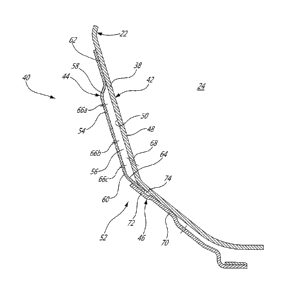
Fig. 3 shows a portion of Fig. 2, enlarged to show detail.
DETAILED DESCRIPTION
Fig.1 illustrates a turbofan gas turbine engine 10 of a type preferably
provided for
use in subsonic flight, generally comprising in serial flow communication a
fan 12 through
which ambient air is propelled, a multistage compressor 14 for pressurizing
the air, a
combustor 16 in which the compressed air is mixed with fuel and ignited for
generating an
annular stream of hot combustion gases, and a turbine section 18 for
extracting energy
from the combustion gases.
The combustor 16 shown in Fig. 1 is of the reverse-flow type and is provided
in the
form of a ring extending circumferentially around the engine axis 11. The
combustor 16 has
a wall 22 delimiting a combustion chamber 24, and the wall 22 has a radially-
outer portion
- 3 -
CA 02830049 2013-10-10
=
26. An annular stream of compressed air exits a centrifugal compressor stage
28 externally
from the combustor 16 and envelops the radially-outer portion 26 of its wall
22. Air typically
enters the combustion chamber 24 in a radially inward direction relative to
the axis 11,
across apertures (not shown) provided in the radially-outer portion 26 of the
combustor wall
22. Fuel is typically provided from a plurality of circumferentially
interspaced fuel nozzles 20
which spray fuel in an atomized state into the combustion chamber 24 across
associated
apertures typically provided in a rear wall portion 30 of the combustor 16.
The combusting
fuel and air mixture thus travels partially forward inside a portion of the
combustion chamber
24, in a direction opposite the general gas path direction 32 across the gas
turbine engine
10, prior to elbowing and exiting an exit duct portion 34 of the combustor 16
leading to the
first turbine stage 36 in a direction corresponding to the general gas path
direction 32
across the gas turbine engine 10.
Referring to Fig. 2, a portion 38 of the combustor wall 22 forming a portion
of the
elbow at a front end thereof is particularly subjected to impinging heat from
the combusting
fuel and air mixture. To manage this heat, and thereby favour a greater
expected lifespan of
the combustor wall 22, this portion 38 of the combustor wall is provided with
a cooling
system which includes a double skin assembly 40.
The skin assembly 40 is shown in greater detail in Fig. 3. A portion 38 of the
combustor wall 22 forms a first one of these skins. Since this first skin has
an inner face 48
directly exposed to the combustion gasses in the combustion chamber 24 during
operation
of the gas turbine engine 10, its temperature rises higher than the
temperature of the
second skin. Henceforth, the portion 38 of the combustor wall 22 is referred
to as the hot
skin 42 and the second skin is referred to as the cold skin 44. It will be
understood that both
skins 42, 44 are typically provided in the form of an annulus extending around
the main axis
11 of the engine 10. Given this general annular shape or circumferential
symmetry, the
cross-section of a portion of the annulus shown in Fig. 3 can be understood to
be generally
representative of the shape of assembly 40.
In this embodiment, the skin assembly 40 generally includes three components :
the hot skin 42, the cold skin 44, and a receiving skin 46. The cold skin 44
and the receiving
skin 46 are both affixed to the outer face 50 of the hot skin 42 and form an
airtight sliding
engagement 52 with one another. In this embodiment, all three skins 42, 44, 46
of the
- 4 -
CA 02830049 2013-10-10
assembly are formed of a sheet metal material known in the art as being
resistant to the
conditions of use in a combustor, such nickel-chromium, or cobalt based super
alloys
manufactured under the registered trademark INCONEL, or HAYNES, for instance.
The cold skin 44 is shaped with a portion which will be referred to herein as
the
cold wall portion 54, which is maintained spaced apart from the hot skin 42 to
form a cooling
cavity 56 therebetween. Referring to the section of the annular cold skin 44
shown in Fig. 3,
the cold wall portion 54 can be said to have a length extending mostly
radially and partly
axially, with two opposite ends which can arbitrarily be referred to as the
first end 58 and the
second end 60. The cold skin 44 has a portion referred to as a securing
portion 62 which
extends from the first end 58 and which is affixed to the outer face 50 of the
hot skin 42 in
an air-tight manner. This can be achieved by welding the securing portion 62
to the hot skin
42, for instance. The cold skin 44 also has a male flange 64 which extends
from the second
end 60 of the cold wall portion 54. The thickness of the male flange 64 is
determined from
the thickness of the metal sheet from which the cold skin 44 is formed, which
can be
manufactured with a relatively high degree of precision in the order of a few
thousands of an
inch using known manufacturing processes. The cold wall portion 54 can have a
plurality of
impingement holes 66a, 66b, 66c which can be spaced both lengthwisely and
circumferentially from one another to allow cooling air circulation
therethrough, whereas the
hot skin 42 can have effusion holes 68 therethrough.
The receiving skin 46 has a portion which will be referred to herein as the
securing
portion 70, by which it is affixed to the outer face 50 of the hot skin 42 in
an air-tight
manner. This can be achieved by welding the securing portion 70 to the hot
skin 42, for
instance. The receiving skin 46 also has a receiving flange 72 which extends
from the
securing portion 70 in an offset manner, thereby forming a female recess 74
between the
receiving flange 72 and the hot skin 42. Given currently available sheet metal
forming
processes, the receiving skin 46 can be formed in a manner that the thickness
of the female
recess, or offset distance, can be repeatable in a highly precise manner, such
as in the
order of a few thousands of an inch, for instance, which allows to precisely
adapt the
thickness of the female recess 74 to the thickness of the male flange 64 of
the cold skin 44,
for the male flange 64 to be snugly received therein in a manner to form an
air tight seal.
- 5 -
CA 02830049 2013-10-10
The female recess 74 can be formed of the same thickness than the male
flange 64, or slightly smaller e.g. about 2 thousands of an inch smaller, and
the components
can be assembled as follows. First the cold skin 44 is welded to the hot skin
42. The cold
skin 44 was formed such that after welding the male flange 64 just rests on
the hot skin.
Second, with the use of a locating fixture, the receiving skin 46 can be
brought in its place.
If the female gap 74 is smaller than the male flange 64, the securing portion
70 of the
receiving skin 46 is not in contact with the hot skin 42. Then, under the
pressure of seam
welding wheels, the securing portion 70 of the receiving skin is forced into
contact with the
hot skin and is welded in place. After welding and the resulting weld
shrinkage, the male
flange is tightly held, thus creating an air-tight seal.
If the female recess 74 can be made smaller than the thickness of the male
flange 64 at ambient temperature to take into account the fact that during the
operating
condition, the female recess 74 can be subjected to growth given the thermal
gradient
between the cold side and the hot side. However, depending on the
configuration and using
as example the configuration illustrated in Fig. 3, the female recess 74 can
also rotate
slightly, due to the thermal gradient, and this rotation can also provide
interfering seal with
the male flange 64. Because the male flange 64 and female recess 74 are not
welded
together they are still able to slide with respect to each other, thus
allowing an evacuation
route to stress occuring upon the differential growth of the hot skin 42 and
cold skin 44.
It will be noted that the receiving skin 46 can advantageously be provided in
the
form of a skin which is also used for another purpose. For instance, in the
illustrated
embodiment, the receiving skin 46 is provided in the form of a leg of the
large exit duct
having the receiving flange 72 provided as an extra portion thereof. In
alternate
embodiments, the receiving flange can be provided as a portion of an other
component than
a large exit duct leg.
The embodiment described above and illustrated can allow a sliding freedom of
movement at one end of the cold skin 44 which can effectively reduce the
amount of
internal mechanical stress it can be subjected to by a relatively greater
thermal growth
occurring with the hot skin to which it is attacked, as compared to a cold
skin having the
same length and being welded to the hot skin at both ends. Moreover, the lower
internal
- 6 -
CA 02830049 2013-10-10
=
mechanical stress is achieved in this embodiment in a cost-effective, and
relatively low
weight manner.
The sliding skin assembly 52 can not only be manufactured as a component of
new
engines, it can be used on replacement combustor parts, or even potentially
retro-fitted to
existing engine designs.
The above description is meant to be exemplary only, and one skilled in the
art will
recognize that changes may be made to the embodiments described without
departing from
the scope of the invention disclosed. For example, the type of combustor to
which the skin
assembly is adapted to, the materials identified above, and the configuration,
shape, and
size of the skins can vary in alternate embodiments. Still other modifications
which fall within
the scope of the present invention will be apparent to those skilled in the
art, in light of a
review of this disclosure, and such modifications are intended to fall within
the scope of the
appended claims.
- 7 -