Note: Descriptions are shown in the official language in which they were submitted.
CA 02830402 2013-10-21
TITLE: Visual Monitoring System for Covered Storage Tanks
FIELD OF THE INVENTION
[0001] This invention relates to the remote visual monitoring of the space
between the floating
roof and the fixed roof of a covered aboveground storage tank (AST). This
monitoring system
can be used to view visible or invisible optical wavelengths and is used to
monitor for fires,
leaks, mechanical problems, and other hazardous conditions, or to determine
the elevation of the
floating roof within the AST. Additionally, since the appearance of the space
being monitored
does not often change, alarm conditions or operator notifications can be
triggered when the
visual field of the camera changes. The monitoring system can use wired or
wireless means, or a
combination thereof, for communication.
BACKGROUND OF THE INVENTION
[0002] The processing and storage of chemical compounds, such as
petrochemicals, is quite
widespread. Since many of these compounds can be toxic, flammable, or
potentially explosive,
there are grave safety concerns for personnel and for the environment.
Additionally, the capital,
environmental, and human costs of a disaster at a processing facility can be
staggering.
[0003] In the petroleum industry, each large aboveground storage tank (AST)
has a roof that
floats on top of the stored liquid. This prevents having a potentially
explosive vapor space
between the liquid and the roof of the AST. The roof typically floats on
pontoons and has a
flexible seal around its perimeter to minimize the escape of liquid or vapor
from the inside of the
AST. However, the escape of at least small quantities of liquid or vapor is
inevitable.
1
CA 02830402 2013-10-21
[0004] Covered AST's have a fixed roof above the floating roof that serves
both to protect the
floating roof and to reduce the amount of evaporation into the atmosphere. In
the petroleum
storage industry, a current industry practice for monitoring covered AST's is
to perform manual
inspections through roof hatches. A minimal visual inspection can check that
the floating roof
appears to be floating properly, that there is no visible liquid on the roof,
and that the seal is
visibly intact. Additional manual inspections include measuring the internal
atmosphere to
check that it has a volatile gas concentration that is less than prescribed
limits.
[0005] Manual inspection is generally non-comprehensive and, since it occurs
infrequently,
such as annually or monthly, it could miss the timely detection of a
potentially catastrophic
condition. Remote monitoring makes it operationally feasible to inspect and
monitor the AST
more frequently and thoroughly, thereby facilitating the detection of
potentially hazardous
conditions in a timelier manner. The AST can be inspected at scheduled
intervals, on demand, or
when monitoring devices such as gas sensors detect an anomalous condition.
[0006] Another operational hazard is the overfilling of AST's. When an AST is
overfilled, the
elevation of the floating roof within the tank is excessive and large
quantities of liquid can
escape from the AST, often with dire consequences such as catastrophic fires.
BRIEF SUMMARY OF THE INVENTION
=
2
CA 02830402 2013-10-21
[0007] The current invention is a visual monitoring system and a related
method for the visual
monitoring of the space between the floating roof and the fixed roof of a
covered above ground
storage tank (AST).
[0008] This invention is presented in the context of use in the petrochemical
industry where the
integrity of the floating roof, the escape of liquid or gas, and fires are of
great concern but it is
also suitable for deployment for other industrial applications.
[0009] The invention comprises two types of units that communicate using
wireless means.
The Imaging Unit includes at least one digital camera and at least one
wireless communication
link. The Communication Unit contains at least one wireless communication link
and may also
contain one or more wired communication links. The Communication Unit is used
to relay
information from the Imaging Unit to the system operator or to a remote
monitoring system by
wired or wireless means. The Communication Unit or the Imaging Unit may also
be directly
connected to an alarm system or an audible or visual alarm by wired or
wireless means.
[0010] The Imaging Unit is battery powered and consequently it is important to
conserve
power. Since the visual field being monitored by the camera does not change
often, one method
of conserving power is to use a low frame acquisition rate. As an example, an
image frame
could be captured once every hour. The frame rate is not necessarily a fixed
value and could be
increased if an anomalous condition is detected.
3
CA 02830402 2013-10-21
[0011] Herein, an anomalous condition is any operational condition that is of
concern to the
plant operator including, but not limited to, the existence of flames,
excessive vibration,
excessive gas concentration, or the improper position of the floating roof.
[0012] When compared to the current industry practice of manual inspection,
major benefits of
the current invention include: inspection at more frequent intervals (e.g.,
multiple times per day),
thereby improving the probability of the timely detection of a potentially
catastrophic event and
avoiding the exposure of personnel to potentially hazardous conditions. It
also features low
power consumption, thereby allowing long-term autonomous operation.
[0013] The proposed invention can also be used to optically monitor the
elevation of the
floating roof within the AST, thereby helping to reduce the danger of
overfilling the AST.
[0014] [0015]A further potential benefit of the invention is that the ease of
installation and low
installed cost may serve to hasten the upgrading of safety systems.
BRIEF DESCRIPTION OF THE DRAWINGS
[0016] Figure 1: Functional Block Diagram of the Proposed Apparatus
[0017] Figure 2: Functional Block Diagram of the Imaging Unit
[0018] Figure 3: Functional Block Diagram of the Communication Unit
[0019] Figure 4: A side elevation view, in section, of a visual monitoring
system for covered
storage tanks.
4
CA 02830402 2013-10-21
DETAILED DESCRIPTION OF THE INVENTION
[0020] With reference to the block diagram in Figure 1, the invention
minimally comprises a
Communication Unit 1 and an Imaging Unit 2 that communicate via wireless means
using
Antennas 3. The configuration of the Antennas 3 is not a facet of this
invention.
[0021] With reference to the block diagram in Figure 2, the Imaging Unit 2
comprises an
Antenna 3; one or more digital Cameras 4; a Microcontroller or Microprocessor
5; an
electrochemical Power Source 6; and a Wireless Communication Interface 7. Said
Wireless
Communication Interface 7 can be integrated with said Microcontroller 5, e.g.,
the Freescale
MC13224.
[0022] With reference to the block diagram in Figure 3, the Communication Unit
1 minimally
comprises an Antenna 3; a Microcontroller or Microprocessor 5; a Power Source
6 such as solar
panels, a connection to an external power source, or an electrochemical power
source; and a
Wireless Communication Interface 7. It may include additional wireless or
wired interfaces.
[0023] In the current embodiment of both the Communication Unit 1 and the
Imaging Unit 2,
the Microcontroller 5 and Wireless Communication Interface 7 is realized using
a Freescale
MC13224; the Power Source 6 is a lithium-thionyl-chloride battery pack; and
the Antenna 3 is a
patch antenna.
[0024] There are multiple variants of the current embodiment of the Imaging
Unit 2. For an
Imaging Unit that is used for monitoring visible wavelengths, the Camera 4 is
a Firefly MV from
5
CA 02830402 2013-10-21
Point Grey Research whereas for an Imaging Unit 2 that is used for monitoring
wideband
thermal infrared wavelengths, the Camera 4 is a thermoImager TIM 400 from
Micro-Epsilon.
Additionally, a Camera 4 can be a multispectral imaging system that captures
separate images
for each of a plurality of bands of spectral wavelengths. Said multispectral
imaging systems can
more accurately detect specific anomalous conditions such as flames.
[0025] Multispectral methods for flame detection are more reliable than
wideband infrared
methods and are well known in the existing art, but imaging multispectral
sensors have not yet
been employed within AST's. Because an imaging multispectral sensor provides
positional
information for a detected event, rather than simply an indication of the
occurrence of said event,
the current invention introduces the use of multispectral imaging within an
AST.
[0026] The Imaging Unit 2 is designed for long-term battery-powered operation
and it is
therefore advantageous to minimize power consumption. Acquiring a digital
image from the
Camera 4 requires a significant amount of power, as does transmitting said
image from the
Imaging Unit 2 to the Communication Unit 1. Hereinafter we further describe
the current low-
power embodiment of the Imaging Unit 2.
[0027] To reduce the amount of power consumed by image acquisition, the image
is acquired
only when requested by the system operator or if some other device, such as a
gas sensor detects
an anomalous condition and subsequently signals the Imaging Unit 2 using wired
or wireless
means. Additionally, the current invention can be used to acquire the image at
scheduled
intervals.
6
CA 02830402 2013-10-21
[0028] The amount of power consumed by transmitting the image from the Imaging
Unit 2 to
the Communication Unit 1 can be reduced by employing various encoding methods.
One class
of said encoding methods compresses the data from each individual image that
is acquired by the
Camera 4 using commonly-available algorithms such as JPEG 2000, which is
lossy, or entropy
coding, which is lossless. Since said compressed image comprises fewer bits of
information than
an uncompressed image, the power required to transmit the image is thereby
reduced.
[0029] A second class of said encoding methods employs motion-video encoding,
such as
MPEG-4 or H.264. Although the frame rate used by this invention is quite low
compared to
common video-encoding applications, motion video encoding is appropriate
because the visual
field monitored by the Camera 4 does not often change. When compared to the
said encoding of
individual images, motion-video encoding greatly reduces the amount of data
that needs to be
transmitted from the Imaging Unit 2 to the Communication Unit 1, thereby
reducing power
consumption.
[0030] The visual field monitored by this invention is essentially invariant
unless the AST is
being filled or being emptied. Therefore, a change in the visual field can be
used to indicate a
potentially hazardous anomaly, such as a failed pontoon, a leaking seal, or a
fire. Consequently,
said change can be used to trigger an alarm or an operator notification.
Methods for detecting
changes in a visual field are well known in the current art and are not a
facet of this invention.
7
CA 02830402 2013-10-21
[0031] A further aspect of this invention is that it can be used to determine
the elevation of the
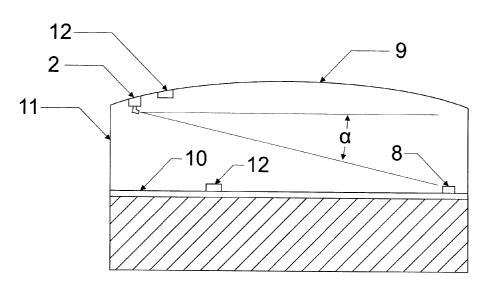
floating roof inside of the AST. With reference to Figure 4, the Imaging Unit
2 can be attached
to the Ceiling 9 or Wall 11 of the AST. The location of said Imaging Unit 2
and the location of
one or more visible Markers 8, wherein said Markers are located on the
Floating Roof 10, can be
determined during installation. When filling or emptying the AST, the Floating
Roof 10 rises or
falls within the AST, and the angle a will thereby decrease or increase,
respectively. Therefore,
the distance from the Floating Roof 10 to the top of the AST can be determined
by using
elementary trigonometry. This aspect of the invention can be used in the
prevention of the
overfilling of AST's. Said visible marker is any physical feature on the AST
or any additional =
marker or marking that can be discerned using any of the visible or invisible
wavelengths
monitored by any Camera 4. By using the location of a said Marker within an
image from a
Camera 4, the elevation of the roof can be manually determined by a human
operator.
Alternatively, the location of said Marker within said image can be
automatically determined
using known methods from computer vision, thereby enabling the automated
computation of the
elevation of the Floating Roof 10.
[0032] A plurality of Cameras 4 can be integrated into a single Imaging Unit 2
to provide
redundancy, to provide additional spectral coverage, or for extending the
field of view. Any
Camera 4 can be mounted on a pan/tilt mechanism to extend its effective field
of view. Any
Camera 4 can have a zoom lens for varying its field of view.
[0033] A plurality of Imaging Units 2 can be deployed to improve the coverage
of the area
being monitored or to monitor multiple portions of the electromagnetic
spectrum, such as visual
8
CA 02830402 2013-10-21
and infrared. A plurality of Communication Units 1 can be deployed to provide
spatial diversity
or frequency diversity for the wireless signals or to provide redundant
communication links for
safety-critical systems. Any Communication Unit 1 or Imaging Unit 2 can employ
multiple
Antennas 3 for the purpose of antenna diversity or frequency diversity.
[0034] The acquisition of an image can be performed at regular time intervals
or image
acquisition can be triggered by anomalous conditions that are detected by one
or more Sensors
12, such as a gas sensor, inclinometer, accelerometer, or optical flame
sensor.
[0035] As required for any particular deployment, the communication system of
the Imaging
Unit 2 or the Communication Unit I can be configured to act as a communication
relay or as part
of a redundant network, such as a mesh network. These capabilities are well
known in the
existing art.
[0036] Because the Imaging Unit 2 and the Communication Unit 1 can have a
minimal number
of external physical connections, including the possibility of zero external
connections, they can
be readily protected by an environmentally-protective enclosure, thereby
making them suitable
for use in harsh environments. The current embodiment of the Imaging Unit 2 is
intended for
deployment within petroleum AST's and meets the ATEX requirements for
Intrinsic Safety,
although these are not requirements of the current invention.
9