Note: Descriptions are shown in the official language in which they were submitted.
CA 02830499 2013-09-17
Attorney Ref: 1179P009CA01
VIRTUAL GOLF SIMULATION APPARATUS AND SENSING DEVICE AND
METHOD USED FOR THE SAME
Field of the Invention
The present invention relates to a virtual golf simulation apparatus and a
sensing device and method used for the same, and more particularly to a
virtual
golf simulation apparatus in which a virtual golf course is imaged and
simulated,
and the trajectory of a golf ball hit by a user is sensed by a sensing device
and is
simulated on the virtual golf course, and a sensing device and method used for
the
same.
Background
In recent years, various devices have been developed which allow users to
enjoy popular sports games, such as baseball, soccer, basketball and golf, in
rooms
or in specific places through simulation in the form of interactive sports
games.
Particularly, in recent years, a so-called screen golf system has been
developed in which, when a user swings a golf club to hit a golf ball placed
on a
hitting mat, a sensing device senses the hit golf ball to extract physical
information on the moving golf ball so that the trajectory of the golf ball
can be
simulated on a virtual golf course, thereby allowing the user to enjoy golf in
virtual reality.
In order to simulate sports using balls, such as golf balls, in such
interactive sports games, much research has been conducted into various
sensing
systems for accurately sensing physical information on a moving ball, i.e.
movement of a ball.
For example, various sensing devices, such as a sensing device using an
1
CA 02830499 2013-09-17
Attorney Ref: 1179P009CA01
infrared sensor, a sensing device using a laser sensor, a sensing device using
an
acoustic sensor and a sensing device using a camera sensor, have come onto the
market. Much research has been conducted into a camera sensor type sensing
device for acquiring and analyzing an image of a moving ball to accurately
sense a
state of the moving ball.
In the camera sensor type sensing device, however, an ultrahigh-speed
camera having a high resolution is necessary for accurate sensing, which
greatly
increases costs of the sensing device. On the other hand, if a camera having a
relatively low resolution and a relatively low speed is used, the quality of
an image
acquired by the camera is low with the result that it is very difficult to
accurately
extract and analyze a ball.
It is an object of the present invention to provide a virtual golf simulation
apparatus and a sensing device and method used for the same in which an image
of a golf ball hit by a user using virtual golf simulation, who swings a golf
club to
hit the golf ball, is acquired, and the golf ball is found from the acquired
image to
calculate the moving trajectory of the golf ball, thereby realizing a
simulation
image of the trajectory of the golf ball, and, particularly, in which two-
dimensional
trajectories of ball candidates, recognized as a ball, in an image acquired by
the
camera are analyzed to accurately and rapidly extract the ball, thereby
accurately
and rapidly calculating information on physical properties of the moving ball
even
using a camera having a low resolution and velocity.
Summary of the Invention
In accordance with an aspect of the present invention, the above and
other objects can be accomplished by the provision of a sensing device used in
a
virtual golf simulation apparatus, including a camera unit for acquiring a
plurality
2
CA 02830499 2013-09-17
Attorney Ref: 1179P009CA01
of frame images of a ball hit by a user who swings at the ball and a sensing
processing unit for extracting ball candidates from the acquired frame images,
converting three-dimensional coordinates of each of the ball candidates into
two-
dimensional coordinates, and analyzing a two-dimensional trajectory of each of
the ball candidates to extract a trajectory of the ball, thereby calculating
information on physical properties of the moving ball.
In accordance with another aspect of the present invention, there is
provided a virtual golf simulation apparatus including a sensing device
including
a camera unit for acquiring a plurality of frame images of a ball hit by a
user who
swings at the ball and a sensing processing unit including a ball trajectory
listing
means for extracting ball candidates from the respective frames with respect
to the
acquired images and for creating a ball trajectory list to connect the
respective ball
candidates with respect to the successive frames and a ball trajectory
determination
means for performing second-order polynomial regression analysis with respect
to
the created ball trajectory list to create ball trajectory candidates and for
extracting
the trajectory of a ball from the ball trajectory candidates according to a
predetermined condition, and an image realization unit for realizing a
simulation
image of a trajectory of the ball based on the information extracted by the
sensing
processing unit.
In accordance with a further aspect of the present invention, there is
provided a sensing method for virtual golf simulation, including acquiring a
plurality of frame images of a ball hit by a user who swings at the ball,
extracting
ball candidates from the acquired frame images, converting three-dimensional
coordinates of each of the ball candidates into two-dimensional coordinates to
extract a two-dimensional trajectory of each of the ball candidates, and
analyzing
the two-dimensional trajectory of each of the ball candidates to extract a
trajectory
3
CA 02830499 2013-09-17
Attorney Ref: 1179P009CA01
of the ball, thereby calculating information on physical properties of the
moving
ball.
The virtual golf simulation apparatus and a sensing device and method
used for the same according to the present invention has effects that an image
of a
golf ball hit by a user using virtual golf simulation, who swings a golf club
to hit
the golf ball, is acquired, and the golf ball is found from the acquired image
to
calculate the moving trajectory of the golf ball, thereby realizing a
simulation
image of the trajectory of the golf ball, and, particularly, in which two-
dimensional
trajectories of ball candidates, recognized as a ball, in an image acquired by
the
camera are analyzed to accurately and rapidly extract the ball, thereby
accurately
and rapidly calculating information on physical properties of the moving ball
even
using a camera having a low resolution and velocity.
Brief Description of Drawings
FIG. 1 is a view showing an example of a screen golf system to which a
virtual golf simulation apparatus according to an embodiment of the present
invention is applied;
FIG. 2 is a block diagram showing the construction of a virtual golf
simulation apparatus according to an embodiment of the present invention;
FIG. 3 is a view schematically showing more detailed construction of a
sensing device shown in FIG. 2 and functions of components constituting the
sensing device;
FIG. 4(a) is a view showing an image acquired by a camera unit, and
FIG. 4(b) is a view showing a source image obtained by separating a region
corresponding to a predetermined section from the image shown in FIG. 4(a);
FIG. 5(a) is a view showing a source image, FIG. 5(b) is a view showing
4
CA 02830499 2013-09-17
Attorney Ref: 1179P009CA01
a still background image, and FIG. 5(c) is a view showing an image obtained by
removing the background image from the source image;
FIG. 6(a) is a view showing ball candidates of several frames on an
image obtained by combining several frames, which are processed as shown in
FIGS. 4 and 5 to extract ball candidates, and FIG. 6(b) is a view showing a
ball
template T preset and stored as a reference image of a ball;
FIG. 7 is a view showing finally selected ball candidates in respective
frames;
FIG. 8 is a view showing an example of combining ball candidates in the
3.0 respective frames shown in FIG. 7 to create a ball trajectory list;
FIG. 9 is a view showing a coordinate system used in the sensing device
of the virtual golf simulation apparatus according to the embodiment of the
present invention;
FIG. 10 is a view showing ball trajectory candidates derived by mapping
the ball trajectory list shown in FIG. 8 on a yz plane;
FIG. 11 is a view illustrating physical properties of a moving ball; and
FIG. 12 is a flow chart showing a sensing method for virtual golf
simulation according to an embodiment of the present invention.
Detailed Description
Now, exemplary embodiments of a virtual golf simulation apparatus
according to the present invention and a sensing device and method used for
the
same will be described in detail with reference to the accompanying drawings.
First, a virtual golf simulation apparatus according to an embodiment of
the present invention and a sensing device used in the same will be described
with
reference to FIGS. 1 and 2.
5
CA 02830499 2013-09-17
Attorney Ref: 1179P009CA01
FIG. 1 is a view showing an example of a screen golf system to which a
virtual golf simulation apparatus according to an embodiment of the present
invention is applied, and FIG. 2 is a block diagram showing the construction
of a
virtual golf simulation apparatus applied to the screen golf system shown in
FIG.
1.
As shown in FIGS. 1 and 2, the virtual golf simulation apparatus
according to the embodiment of the present invention includes a sensing device
S
for sensing a golf ball B hit by a user and a simulator 1 for realizing an
image of a
virtual golf course and providing a simulation image of the trajectory of the
golf
ball B on the virtual golf course based on the result sensed by the sensing
device S
so that virtual golf simulation can be performed.
As shown in FIG. 1, the screen golf system, to which the virtual golf
simulation apparatus according to the embodiment of the present invention is
applied, may be configured to have a structure in which a hitting box 110, on
which a user hits a golf ball B, is provided on the floor of a golf booth 2
providing
a space of a predetermined size, a hitting mat 120, on which a golf ball B is
placed so that the user can hit the golf ball B on the hitting box 110, is
provided at
one side of the hitting box 110, and a screen 3, on which an image of virtual
golf
simulation output from an image output device (an image output part 30 shown
in
FIG. 2, such as a beam projector), to which image information is transmitted
from
the simulator 1, is projected, is provided at the front of the golf booth 2.
The hitting box 110 and the hitting mat 120 are provided on a swing plate
100 as shown in FIG. 1. Alternatively, the hitting box 110 and the hitting mat
120 may be provided on the floor of the golf booth 2.
The swing plate 100 may be provided so that the swing plate 100 can be
sloped at a predetermined angle in the forward and rearward direction and in
the
6
CA 02830499 2013-09-17
Attorney Ref: 1179P009CA01
left and right direction. Also, the swing plate 100 may be connected to the
simulator 1 so that the swing plate 100 can be sloped in correspondence to the
topography of a virtual golf course which is presently being realized.
Meanwhile, as shown in FIG. 1, the sensing device S is provided in the
golf booth 2 to sense a golf ball B hit by a user.
That is, as shown in FIG. 2, the sensing device S may include a camera
unit 50 including a plurality of cameras 51 and 52, and a sensing processing
unit
60 for processing an image acquired by the camera unit 50 to extract physical
properties of the moving golf ball.
The camera unit 50 may be constituted by a single camera for image
sensing or two or more cameras. In order to acquire an image of a moving golf
ball B and extract coordinates of the golf ball in a three-dimensional space,
it is
preferable to configure a stereo type camera unit using two or more cameras 51
and 52, which are operatively connected to each other, as shown in FIG. 1.
The physical properties of the moving golf ball may include velocity of
the golf ball, a moving direction of the golf ball (a moving angle of the golf
ball
in the horizontal direction), an altitude angle of the golf ball (a moving
angle of
the golf ball in the vertical direction), and spin of the golf ball.
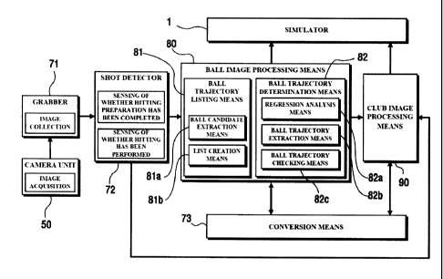
The sensing processing unit 60 may include a grabber 71 for sequentially
collecting images acquired by the camera unit 50 on a per frame basis, a shot
detector 72 for receiving and processing the images collected by the grabber
71 to
sense whether hitting preparation has been completed and whether hitting has
been performed by a user, a ball image processing means 80 for processing an
image of the hit golf ball received from the shot detector 72, when the shot
detector
72 senses that the golf ball has been hit by the user, to extract information
on
physical properties of the moving golf ball, and a club image processing means
90
7
CA 02830499 2013-09-17
Attorney Ref: 1179P009CA01
for analyzing the moving trajectory of a golf club from the image received
from the
shot detector 72 to extract information on spin of the ball.
Also, the sensing processing unit 60 may further include a conversion
means 73 for matching images acquired by the cameras 51 and 52 to convert two-
dimensional information of each camera image (information extracted from each
camera is two-dimensional information) into three-dimensional information or
to
inversely convert three-dimensional information extracted by matching a
plurality
of camera images into two-dimensional information.
Meanwhile, the simulator 1 constituting the virtual golf simulation
apparatus according to the embodiment of the present invention preferably
includes
a controller M, a database 10, an data processing part 20 and an image output
part
30.
The database 10 stores all data necessary for virtual golf simulation. For
example, the database 10 stores data necessary to drive the system, data
necessary
to realize an image of a virtual golf course, and data necessary to realize a
simulation image of the trajectory of a golf ball.
The data processing part 20 is a part which performs predetermined image
processing to realize an image of a virtual golf course or a simulation image
of the
trajectory of a golf ball on the virtual golf course.
The image output part 30 outputs image information received from the
data processing part 20 to a screen so that a user can watch the image.
The controller M receives information based on the result sensed by the
sensing device S to control operations of all components, such as the database
10,
the data processing part 20 and the image output part 30, of the simulator 1.
That
is, the controller M, the database 10 and the data processing part 20 function
as an
image realization unitfor realizing a simulation image of the trajectory of a
golf ball
8
CA 02830499 2013-09-17
,
Attorney Ref: 1179P009CA01
based on the result sensed by the sensing device S.
Hereinafter, more detailed construction of the sensing device S shown in
FIG. 2 and functions of the respective components constituting the sensing
device
will be described with reference to FIG. 3.
5 As shown in
FIG. 3, transmission of information in the sensing device
according to the present invention is carried out in the order of the camera
unit 50
¨> the grabber 71 ¨> the shot detector 72 ¨> the ball image processing means
80
and the club image processing means 90 ¨> the simulator 1.
The camera unit 50 captures a predetermined range including a portion at
10 which the
hitting box and the hitting mat are provided to acquire hundreds of frame
images per second.
The acquired frame images are transmitted to the grabber 71. The
grabber 71 stores the images received from the camera unit 50 and, at the same
time, transmits the images to the shot detector 72 so that which image
processing is
15 carried out.
Preferably, the shot detector 72 finds a ball from the image received from
the grabber and determines whether the ball satisfies a predetermined
condition to
sense whether hitting preparation has been completed. Also, the shot detector
72
determines whether the ball is moved from a position at which the hitting
20 preparation
has been completed to sense whether hitting has been performed by a
user.
A method of the shot detector 72 sensing whether hitting preparation has
been completed and sensing whether hitting has been performed is not the core
of
the present invention, and therefore, a detailed description thereof will be
omitted.
25 Upon sensing
that the user has hit the golf ball, the shot detector 72 stores
an image when the golf ball has been hit and a plurality of frame images
thereafter.
9
CA 02830499 2013-09-17
Attorney Ref: 1179P009CA01
These images are transmitted to the ball image processing means 80 in real
time so
that the images can be processed by the ball image processing means 80.
In addition, upon sensing that the user has hit the golf ball, the shot
detector 72 also stores a plurality of frame images before the golf ball has
been hit
and transmits the stored frame images to the club image processing means 90.
The club image processing means 90 extracts an image of a golf club from the
image received from the shot detector 72 and the image processed by the ball
image processing means 80 to derive the moving trajectory of a head of the
golf
club, thereby estimating spin of the ball.
Information on physical properties of the ball extracted by the ball image
processing means 80 and the club image processing means 90 is transmitted to
the
simulator 1. The simulator 1 outputs a simulation image, in which the ball is
moved on a virtual golf course, based on the received information so that
virtual
golf simulation can be performed.
The ball image processing means 80 basically extracts ball candidates
from the images in the respective frames acquired by the camera unit 50,
converts
three-dimensional coordinates of each of the ball candidates into two-
dimensional
coordinates, and analyzes the two-dimensional trajectory of each of the ball
candidates to extract the final trajectory of the golf ball, thereby
calculating
information on physical properties of the moving golf ball.
Specifically, the ball image processing means 80 preferably includes a ball
trajectory listing means 81 for extracting ball candidates from the respective
frames
with respect to the images acquired by the camera unit 50 and for creating a
ball
trajectory list to connect the respective ball candidates with respect to the
successive frames and a ball trajectory determination means 82 for performing
second-order polynomial regression analysis with respect to the created ball
CA 02830499 2013-09-17
Attorney Ref: 1179P009CA01
trajectory list to create ball trajectory candidates and for extracting the
trajectory of
a ball from the ball trajectory candidates according to a predetermined
condition.
The ball trajectory listing means 81 preferably includes a ball candidate
extraction means 81a for processing the respective frame images to extract
ball
candidates from the respective frames and a list creation means 81b for
combining
the ball candidates in the respective frames to create a ball trajectory list.
The ball trajectory determination means 82 preferably includes a ball
trajectory extraction means 82a for mapping coordinates of the respective ball
candidates of the ball trajectory list created by the list creation means 81b
on a
plane of a three-dimensional coordinate system, i.e. mapping three-dimensional
coordinates of the respective ball candidates into two-dimensional coordinates
on a
plane, to create two-dimensional trajectory, i.e. ball trajectory candidates,
thereby
performing second-order polynomial regression analysis, a regression analysis
means 82b for checking a second-order function of each of the ball trajectory
candidates to extract ball trajectory candidates satisfying a predetermined
condition, and a ball trajectory checking means 82c for checking whether the
ball
trajectory candidates extracted by the regression analysis means 82b satisfy a
predetermined condition based on physical properties of a moving ball to
select the
final trajectory of the ball.
Since the image acquired by each camera contains various kinds of noise
(for example, a specific portion of a landform around the ball, a portion of
the body
of a user, and a head portion of the golf club) having a shape similar to the
ball as
well as an image of the ball, it is necessary to accurately extract the ball
from the
image. To this end, three-dimensional coordinates are mapped into two-
dimensional coordinates to obtain two-dimensional trajectories, and the two-
dimensional trajectories are analyzed to remove two-dimensional trajectories
that
11
CA 02830499 2013-09-17
Attorney Ref: 1179P009CA0 I
can be considered as the trajectory of the ball, to extract two-dimensional
trajectories that can be physically considered as the moving trajectory of the
ball, to
select the final trajectory of the ball, and to obtain coordinates of the ball
on the
selected trajectory of the ball, thereby calculating final physical properties
of the
ball.
Hereinafter, creation of a list through extraction of ball candidates
performed by the ball trajectory listing means and combination of the
extracted ball
candidates will be described with reference to FIGS. 3 to 8.
First, the ball candidate extraction means 81a of the ball trajectory listing
means 81 separates a source image 220 shown in FIG. 4(b) from an image 200
acquired by the camera as shown in FIG. 4(a).
Since the image 200 acquired by the camera contains the entire image of a
wide capturing region, it takes a great deal of time to process the image 200.
For
this reason, a necessary portion is extracted and only the extracted image is
processed, thereby reducing image processing time.
The source image 220 shown in FIG. 4(b) may be defined as an image of a
section ranging from a point Pl, at which hitting has been performed, to a
point P2,
which is distant from the point P1 by a predetermined distance in the forward
direction, of the image shown in FIG. 4(a).
That is, when the ball is hit, the ball flies toward the screen 3 (see FIG.
1).
Consequently, movement of the ball from a point at which hitting has been
performed to a point distant from the point at which the hitting has been
performed
by a predetermined distance in the forward direction is analyzed, thereby
sufficiently calculating information, such as velocity, direction and altitude
angle,
of the ball.
The point P2 shown in FIG. 4(a) may be a position corresponding to the
12
CA 02830499 2013-09-17
Attorney Ref: 1179P009CA01
screen 3 (see FIG. 1) or a position distant from the screen by a predetermined
distance in the inward direction.
The point P1 and the point P2 are designated from the image acquired by
the camera, and an image corresponding to the section between the point Pt and
the
point P2 is separated from the image acquired by the camera to obtain a source
image as shown in FIG. 4(b).
Meanwhile, a background image is removed from the source image
obtained as described above through a difference operation as shown in FIG. 5
to
obtain only ball candidates. For example, a background image 230 shown in FIG.
5(b) may be removed from the source image 220 shown in FIG. 5(a) through a
difference operation to obtain an image having only moving portions as shown
in
FIG. 5(c).
The moving portions on the image 240 extracted through the difference
operation are not considered as a ball. Some of the moving portions may be
noise,
such as a portion of the head of the golf club or a portion of the body of the
user.
Consequently, the ball candidate extraction means 81a designates the
portions considered to be the ball in the image 240 obtained through the
difference
operation based on geometrical properties of the ball as the ball candidates.
For
example, a portion, a large width to height ratio of which is large, cannot be
considered as a ball, and therefore, such a portion is excluded. Also, a
portion,
which has a size of one or two pixels, i.e. which is very small, cannot be
considered
as a ball, and therefore, such a portion is excluded.
The remaining portions of the image obtained based on geometrical
properties of the ball as described above are designated as primary ball
candidates.
The primarily ball candidates are compared with a ball template. The primary
ball
candidates, similar to the ball template to such an extent that a degree of
similarity
13
CA 02830499 2013-09-17
Attorney Ref: 1179P009CA01
is equal to or greater than a predetermined level, are designated as secondary
ball
candidates.
A ball template is an image preset and stored as a reference image of a
ball. Primary ball candidates, numerically similar to the ball template by a
predetermined level, are designated as secondary ball candidates.
The ball candidate extraction means 81a preferably include a template
matching means for matching the primary ball candidates with the ball template
to
extract a degree of similarity therebetween, thereby extracting secondary ball
candidates.
However, it is not easy to compare the ball candidates with the ball
template as described above in order to accurately find a ball. The reason is
that
the size of the ball may be different in different frames. That is, the
capturing
region of the camera is fixed, and the distance between the camera and the
ball is
changed in the capturing region according to the movement of the ball, with
the
result that the sizes of the images of the moving ball in the frames may be
different
from each other. Consequently, the size of the ball may be different in
different
frames, and the size of the ball template is fixed, with the result that it is
difficult to
accurately determine how similar the ball candidates are to the ball template.
For this reason, the template matching means estimates the size of the ball
candidates and variably matches the ball candidates with the ball template
based on
the estimated size of the ball candidates to extract a degree of similarity
therebetween, and therefore, it is possible to find the ball with high
accuracy.
FIG. 6(a) is a view showing ball candidates (primarily extracted ball
candidates) of several frames on an image to illustrate that the template
matching
means variably matches the ball candidates with the ball template, and FIG.
6(b) is
a view showing the ball template T.
14
CA 02830499 2013-09-17
Attorney Ref: 1179P009CA01
In FIG. 6(a), C1-1 and C1-2 indicate ball candidates extracted from a
first frame of a source image, C2-1 indicates a ball candidate extracted from
a
second frame, C3-1 indicates a ball candidate extracted from a third frame,
and
C4-1 indicates a ball candidate extracted from a fourth frame. It can be seen
that
the sizes of the ball candidates in the respective frames are different from
each
other. =
First, the template matching means estimates the size of the ball
candidates C1-1 to C4-1 for variable matching with the ball template. That is,
when a ball candidate is simultaneously captured by a plurality of cameras, it
is
possible to acquire coordinates of the ball candidate in a three-dimensional
space
(two-dimensional information of an image acquired by each camera may be
converted into three-dimensional information by the conversion means 73 (see
FIGS. 2 and 3) and the three-dimensional information may be extracted). Also,
it is possible to obtain information, such as the distance between the ball
candidate and a corresponding one of the cameras, from the coordinates of the
ball candidate to estimate the size of the ball candidate.
In addition, the size of each of the ball candidates estimated as described
above is changed so that the size of each of the ball candidates is equivalent
to the
size of the ball template or the size of the ball template is changed so that
the size
of the ball template is equivalent to the size of each of the ball candidates,
and the
respective ball candidates are compared with the ball template to determine
how
similar the ball candidates are to the ball template, thereby easily finding
which of
the ball candidates are similar to a real ball.
That is, each of the ball candidates is normalized so that the size of each
of the ball candidates is equivalent to the size of the ball template T or the
ball
template T is normalized so that the size of the ball template T is equivalent
to the
CA 02830499 2013-09-17
Attorney Ref: 1179P009CA01
size of each of the ball candidates in consideration of the estimated size of
each of
the ball candidates, and then the ball candidates are compared with the ball
template T.
Normalization of a ball candidate is a process of deforming a ball
candidate image so that the size of the ball candidate is equivalent to the
size of a
ball template T while maintaining the shape and pixel ratio of the ball
candidate
image, thereby achieving easy comparison between the ball candidate and the
ball
template. On the other hand, normalization of a ball template T is a process
of
deforming a ball template image so that the size of the ball template T is
equivalent to the size of a corresponding ball candidate while maintaining the
shape and pixel ratio of the ball template image, thereby achieving easy
comparison between the ball template and the ball candidate.
Upon completing normalization of the ball candidates or the ball
template as described above, the ball candidates are compared with the ball
template to extract a degree of similarity therebetween, thereby selecting the
ball
candidates, having a degree of similarity equal to or greater than a
predetermined
value, as secondary ball candidates.
The degree of similarity is converted into a numerical value determined
based on various determination criteria, such as overall shape, pixel ratio
and
pixel value distribution.
Meanwhile, an example of ball candidates extracted from the respective
frame images by the ball candidate extraction means 81a as described above is
shown in FIG. 7.
It can be seen from the example of FIG. 7 that ball candidates 1_1 and
1_2 are finally extracted from frame No. 1, ball candidates 2_1 and 2_2 are
finally extracted from frame No. 2, and ball candidates 3_1 and 3_2 are
finally
16
CA 02830499 2013-09-17
Attorney Ref: 1179P009CA01
extracted from frame No. 3. Of course, ball candidates as described above may
be extracted from several tens or several hundreds of frames.
The list creation means 81b of the ball trajectory listing means 81
combines the ball candidates illustrated in FIG. 7 according to the number of
cases to create a ball trajectory list.
That is, as shown in FIG. 8, the ball candidates are combined for each
frame according to the number of cases to create a ball trajectory list. FIG.
8
shows only track No. 1 to track No. 5 as a ball trajectory list with respect
to three
frames. Of course, many ball candidates may be combined with respect to
several tens or several hundreds of frames to create tracks.
Meanwhile, when the ball trajectory list is created by the ball trajectory
listing means 81 as described above, the ball trajectory determination means
82
(see FIG. 3) extracts the trajectory of a real ball using the ball trajectory
list to
calculate information on physical properties of the moving ball.
The ball trajectory extraction means 82a of the ball trajectory
determination means 82 extracts three-dimensional coordinate values of the
ball
candidates on the respective tracks of the ball trajectory list (see FIG. 8)
created
by the list creation means 81b (the respective camera images may be matched by
the conversion means 73 (see FIGS. 2 and 3) to extract three-dimensional
information) and maps the three-dimensional coordinate values of the ball
candidates on a two-dimensional plane.
That is, a coordinate system is defined on the assumption that the width
direction, in which the hitting box 110 and the hitting mat 120 are placed, is
an x
axis, the length direction, in which the screen 3 is placed, is a y axis, and
the
perpendicular direction is a z axis, as shown in FIG. 9.
In the coordinate system of the x axis, the y axis and the x axis, the ball
17
CA 02830499 2013-09-17
Attorney Ref: 1179P009CA01
trajectory extraction means 82a maps coordinates of the ball candidates on the
respective tracks of the ball trajectory list on a yz plane. At this time, the
conversion means 73 (see FIGS. 2 and 3) may convert three-dimensional
coordinate information of the ball candidates on the list into two-dimensional
coordinate information on the yz plane.
FIG. 10 is a view showing an example of ball candidates of the ball
trajectory list mapped by the ball trajectory extraction means 82a on the yz
plane.
As shown in FIG. 10, two-dimensional trajectories curve 1 to curve 3, i.e.
ball trajectory candidates, may be derived from the ball candidates 1_1 to 4_2
on
the yz plane according to combination on the ball trajectory list.
A second-order function of each of the ball trajectory candidates, i.e.
each of the two-dimensional trajectories, may be calculated in the form of z =
A +
By + Cy2, where A, B and C are constants. Also, B is a first-order
coefficient,
and C is a second-order coefficient. If C > 0, the two-dimensional trajectory
is
convex downward. On the other hand, If C < 0, the two-dimensional trajectory
is convex upward.
The regression analysis means 82b of the ball trajectory determination
means 82 checks the second-order coefficient of the second-order function of
each
of the ball trajectory candidates to extract the ball trajectory candidates
primarily
approaching the trajectory of the ball.
That is, it can be seen that curve 2 and curve 3 of the two-dimensional
trajectories shown in FIG. 10 are excessively convex downward, penetrating the
ground.
If a ball is actually hit, the ball flies over the ground but does not
penetrate the ground. For this reason, curve 2 and curve 3 convex under the
ground may be incorrect trajectories or trajectories containing a trajectory
of the
18
CA 02830499 2013-09-17
Attorney Ref: 1179P009CA01
golf club.
Consequently, the trajectories excessively convex under the ground, i.e.
curve 2 and curve 3, may be excluded.
That is, the incorrect trajectories or the trajectory of the golf club may be
confirmed by checking the second-order coefficient of each of the second-order
function. If a
second-order coefficient of a trajectory is less than a
predetermined value, it is determined that the trajectory is an incorrect
trajectory
or a trajectory of a golf club, and therefore, the trajectory may be excluded.
Such a predetermined value may be properly preset through experimentation.
If the number of the ball trajectory candidates extracted by the regression
analysis means 82b is 1 as described above, the ball trajectory candidate may
be
determined as the trajectory of the ball. On the other hand, if the number of
the
ball trajectory candidates extracted by the regression analysis means 82b is
greater
than 1, an incorrect trajectory(s) is removed based on another specific
criterion to
obtain the final trajectory of the ball.
If the number of the ball trajectory candidates extracted by the regression
analysis means 82b is greater than 1, the ball trajectory checking means 82c
of the
ball trajectory determination means 82 checks whether coordinate movement of
the
respective ball candidates on the trajectories of the respective ball
trajectory
candidates satisfies a predetermined condition and selects the ball trajectory
candidate satisfying the predetermined condition as the final trajectory of
the ball.
The predetermined condition applied to the ball trajectory checking means
82c may be set from physical properties of a moving ball as shown in FIG. 11.
As shown in FIG. 11, a horizontal velocity of a ball may be defined as Vo
cos0 and a vertical velocity of a ball may be defined as Vo sin0 on the
assumption
that the ball is moved at an initial velocity Vo and an altitude angle 0.
19
CA 02830499 2013-09-17
Attorney Ref: 1179P009CA01
As the ball is moved, the horizontal velocity Vy of the ball is maintained
as Vo cos without change, and the vertical velocity Vz of the ball becomes Vo
sine
¨ gt due to the acceleration of gravity gt (where, t indicates moving time of
the
ball).
That is, theoretically, when the ball is moved as shown in FIG. 11, the
coordinates of the ball are moved at uniform velocity in the y axis direction,
and
the coordinates of the ball are moved at uniform acceleration in the z axis
direction.
However, actually, when the ball is moved, various variables, such as
resistance of air, exist according various environments. As a result, the ball
is not
moved as shown in FIG. 11. In a case in which the ball is moved within a very
short section, however, effects caused by various variables may be ignored,
and
therefore, the theoretical properties as shown in FIG. 11 are accurately
applied to a
certain extent.
That is, in a case in which movement of a ball from the hitting mat 120 to
the screen 3 is sensed by the sensing device in the screen golf system shown
in
FIG. 1, the length of the section is very short, for example, approximately 5
m to 7
m. Consequently, it may be considered that the ball is moved according to the
theoretical properties as shown in FIG. 11.
Consequently, the ball trajectory checking means 82c checks coordinate
movement of the respective ball candidates on the ball trajectory candidates,
extracts the ball trajectory candidate moving at almost uniform velocity in
the y
axis direction and at almost uniform acceleration in the z axis direction, and
determines the extracted ball trajectory candidate as the final trajectory of
the ball.
Coordinates of each ball on the trajectory extracted as the final trajectory
of the ball as described above are converted into three-dimensional
coordinates
(two-dimensional coordinates may be converted into three-dimensional
coordinates
CA 02830499 2013-09-17
Attorney Ref: 1179P009CA01
by the conversion means 73 (see FIGS. 2 and 3)), and coordinate movement of
each ball in a three-dimensional space is analyzed to calculate information on
physical properties of the moving ball.
Hereinafter, a sensing method for virtual golf simulation according to an
embodiment of the present invention will be described with reference to FIG.
12.
First, when virtual golf simulation is commenced, a user places a ball on
the hitting mat so that the user can hit the ball. At this time, the sensing
device
acquires an image of the ball placed on the hitting mat, and finds a ball from
the
acquired image (S10). Such a ball finding process is carried out by the shot
detector.
The ball is found from the acquired image and information on
coordinates at which the ball is placed is confirmed. If a predetermined
condition is satisfied, hitting preparation is completed (S11).
Upon completing hitting preparation, the shot detector starts to sense
whether hitting has been completed by the user (S12). Upon sensing that
hitting
has been completed (S20), the shot detector confirms when hitting has been
completed, collects a frame image when hitting has been completed and a
plurality of frame images thereafter (S31), and transmits the collected frame
images to the ball image processing means. On the other hand, upon sensing
that hitting has not been completed, the procedure returns to the hitting
sensing
step (S12).
If the shot detector collects the plurality of frame images and transmits
the collected frame images to the ball image processing means in real time
after
sensing that hitting has been completed, the ball image processing means
separates a predetermined region from the received image to extract a source
image (S32).
21
CA 02830499 2013-09-17
Attorney Ref: 1179P009CA01
Subsequently, the ball image processing means removes a background
image from the extracted source image (S33) to extract ball candidates (S34).
Extraction of the ball candidates was previously described in detail, and
therefore,
a further description thereof will be omitted.
After the ball candidates are extracted for each frame, the ball candidates
of the successive frames are combined to create a ball trajectory list (S40).
The ball trajectory list is polynomial regressed on a yz plane to extract
two-dimensional trajectories, i.e. ball trajectory candidates (S51).
Since the respective ball trajectory candidates are two-dimensional
trajectories, second-order functions of the respective ball trajectory
candidates are
calculated (S52), and a second-order coefficient of each of the calculated
second-
order functions is compared with a predetermined value to extract only the
ball
trajectory candidates having a second-order coefficient equal to or greater
than the
predetermined value (S53).
Of the extracted ball trajectory candidates, the ball trajectory candidate,
coordinate movement of the ball candidates of which satisfies a predetermined
condition (the uniform velocity motion condition in the horizontal direction
and the
uniform acceleration motion condition in the vertical direction as shown in
FIG.
11), is determined as the final trajectory of the ball (S61).
Subsequently, coordinates of the ball on the determined trajectory of the
ball are converted into three-dimensional coordinates (S62) to calculate
information on physical properties of the moving ball from the coordinate
values
(S63).
The calculated information on physical properties of the moving ball is
transmitted to the simulator, and the simulator realizes a simulation image of
the
trajectory of the ball based on the received information on physical
properties of
22
CA 02830499 2013-09-17
Attorney Ref: 1179P009CA01
the moving ball (S70).
Various embodiments of the present invention have been described in the
best mode.
The virtual golf simulation apparatus and method and a sensing device
and method used for the same according to the present invention can be used in
industries related to a golf game or so-called Screen Golf for a user to be
able to
play a virtual golf round by golf simulation based on a virtual reality.
23