Note: Descriptions are shown in the official language in which they were submitted.
INTEGRATION BETWEEN 3D MAPS AND FLUOROSCOPIC IMAGES
FIELD OF THE INVENTION
The present invention relates generally to combining
images, and specifically to combining a two-dimensional
fluoroscope image with a three-dimensional map.
BACKGROUND OF THE INVENTION
In current cardiac catheterization systems, the
operating physician must often observe two different
images simultaneously, on two different screens: 2D
fluoroscopic images of the thorax and 3D maps of the
heart. Such 3D maps may be generated, for example, using
magnetic tracking of the catheter tip in the heart. Both
the fluoroscopic images and the 3D maps may show the
catheter, but from different angles and perspectives.
Because of the lack of automatic registration and
coordination between the fluoroscopic and 3D views, the
physician is required to switch his or her attention back
and forth between the displays and mentally register the
different information that they contain.
Various methods are known in the patent literature
for automatically registering a fluoroscopic image with a
3D map. Such methods are described, for example, in U.S.
Patent 6,314,310.
To the extent any terms are defined in documents
identified in this description in a manner that conflicts
with the definitions made explicitly or implicitly in the
present specification, only the definitions in the
present specification should be considered.
1
CA 2830552 2019-10-03
SUMMARY OF THE INVENTION
An embodiment of the present invention provides a
coordinate system registration module, including:
radiopaque elements arranged in a fixed
predetermined pattern and configured, in response to the
radiopaque elements generating a fluoroscopic image, to
define a position of the module in a fluoroscopic
coordinate system of reference; and
one or more connections configured to fixedly
connect the module to a magnetic field transmission pad
at a predetermined location and orientation with respect
to the pad, so as to characterize the position of the
registration module in a magnetic coordinate system of
reference defined by the magnetic field transmission pad.
In a disclosed embodiment, the module includes a
pair of parallel plates defining a line of symmetry, and
the radiopaque elements include a plurality of radiopaque
markers distributed symmetrically about the line.
In an alternative disclosed embodiment, the module
includes a pair of parallel plates defining a line of
symmetry, and the radiopaque elements include a
radiopaque predetermined two-dimensional shape centered
on the line of symmetry and orthogonal thereto.
Typically, the predetermined shape is selected from a
group including a disk and a rectangle.
There is further provided, according to an
embodiment of the present invention, a method for
registering coordinate systems, including:
arranging radiopaque elements in a fixed
predetermined pattern within a registration module;
generating a fluoroscopic image of the radiopaque
elements;
2
CA 2830552 2019-10-03
evaluating a fluoroscopic position of the
registration module in a fluoroscopic coordinate system
of reference in response to the fluoroscopic image;
fixedly connecting the registration module to a
magnetic field transmission pad at a predetermined
location and orientation with respect to the pad, so as
to characterize a magnetic position of the registration
module in a magnetic coordinate system of reference
defined by the magnetic field transmission pad; and
registering the fluoroscopic coordinate system with
the magnetic coordinate system by equating the
fluoroscopic position of the registration module with the
magnetic position of the registration module.
Typically, the module includes a pair of parallel
plates defining a line of symmetry, and the radiopaque
elements include a plurality of radiopaque markers
distributed symmetrically about the line.
Alternatively or additionally, the module includes a
pair of parallel plates defining a line of symmetry, and
the radiopaque elements include a radiopaque
predetermined two-dimensional shape centered on the line
of symmetry and orthogonal thereto. The predetermined
shape may be selected from a group including a disk and a
rectangle.
In an alternative embodiment registering the
coordinate systems includes generating a first
transformation relating the fluoroscope coordinate system
of reference to a registration module coordinate system
of reference, and a second transformation relating the
registration module coordinate system of reference to the
magnetic coordinate system of reference, and generating a
compound transformation consisting of a composition of
3
CA 2830552 2019-10-03
the first and second transformations.
Typically, registering the coordinate systems
includes updating the compound transformation, and
updating the compound transformation includes, in
response to a change in a registration of the coordinate
systems, updating the first transformation while
maintaining the second transformation unchanged.
In a further alternative embodiment the method
includes:
positioning a calibration element having further
radiopaque elements on a table irradiated by a
fluoroscope producing the fluoroscopic image;
generating a further fluoroscopic image of the
calibration element; and
calibrating movements of the table in response to
the further fluoroscopic image.
The calibration element may include a ruler disposed
at a known angle to the table.
In a yet further alternative embodiment the method
includes generating a three-dimensional map of an object
in the magnetic coordinate system of reference, and
generating a two-dimensional fluoroscopic image including
the object in the fluoroscopic coordinate system of
reference, and aligning and positioning the two-
dimensional fluoroscopic image with respect to the three-
dimensional map in response to registering the
fluoroscopic coordinate system with the magnetic
coordinate system.
Typically, generating the three-dimensional map of
the object includes generating the map in a first
orientation of the object, and generating the two-
dimensional fluoroscopic image in a second orientation of
4
CA 2830552 2019-10-03
the object, and wherein aligning and positioning the two-
dimensional fluoroscopic image with respect to the three-
dimensional map includes altering one of the map and the
image so that the map and the image align.
There is further provided, according to an
embodiment of the present invention, a coordinate system
calibration jig, including:
radiopaque elements arranged in a fixed
predetermined pattern and configured, in response to the
radiopaque elements generating a fluoroscopic image, to
define a position of the jig in a fluoroscopic coordinate
system of reference; and
one or more connectors configured to receive
magnetic sensors in respective predetermined fixed
locations and orientations with respect to the jig, so
that signals from the magnetic sensors in response to a
magnetic field traversing the sensors characterize the
position of the jig in a magnetic coordinate system of
reference defined by the magnetic field.
The predetermined pattern may include a helix having
a varying period length.
Alternatively or additionally, the predetermined
pattern may include a helix having different numbers of
elements within each period of the helix.
There is further provided, according to an
embodiment of the present invention, a method, including:
arranging radiopaque elements in a fixed
predetermined pattern;
defining, in response to the radiopaque elements
generating a fluoroscopic image, a position of the jig in
a fluoroscopic coordinate system of reference; and
configuring one or more connectors to receive
5
CA 2830552 2019-10-03
magnetic sensors in respective predetermined fixed
locations and orientations with respect to the jig, so
that signals from the magnetic sensors in response to a
magnetic field traversing the sensors characterize the
position of the jig in a magnetic coordinate system of
reference defined by the magnetic field.
In one embodiment, there is provided a coordinate
registration system comprising: a magnetic field
transmission pad configured to transmit an alternating
magnetic field; and a coordinate system registration
module. The coordinate system registration module
comprises: a pair of radio-transparent parallel plates,
the parallel plates being separated by a fixed distance
defined by connectors joining the two plates; radiopaque
elements arranged in fixed predetermined patterns in the
parallel plates and configured, in response to the
radiopaque elements generating an image on a fluoroscopic
system, to define a location and orientation of the
module in a fluoroscopic coordinate system of reference;
and one or more connections. The one or more connections
are configured to fixedly connect the module to the
magnetic field transmission pad at a predetermined
location and orientation with respect to the pad, so as
to enable the location and orientation of the
registration module in a magnetic coordinate system of
reference defined by the magnetic field transmission pad
to be determined. The parallel plates define a line of
symmetry, and the radiopaque elements comprise i) a
plurality of radiopaque markers distributed symmetrically
about the line and ii) a radiopaque predetermined two-
dimensional shape centered on the line of symmetry and
orthogonal thereto. The two-dimensional shape is selected
6
Date Recue/Date Received 2020-08-25
from a group comprising a disk and a rectangle.
In one embodiment, there is provided a method of
registering coordinate systems. The method includes:
arranging radiopaque
elements in fixed predetermined
patterns in a pair of radio-transparent parallel plates
within a registration module, the parallel plates being
separated by a fixed distance defined by connectors
joining the two plates; generating a fluoroscopic image
of the radiopaque elements; and evaluating a
fluoroscopic location and orientation of the registration
module in a fluoroscopic coordinate system of reference
in response to the fluoroscopic image. The method further
includes fixedly connecting the registration module to a
magnetic field transmission pad at a predetermined
location and orientation with respect to the pad, so as
to enable a magnetic location and orientation of the
registration module in a magnetic coordinate system of
reference defined by the magnetic field transmission pad
to be determined; and registering the fluoroscopic
coordinate system with the magnetic coordinate system by
equating the fluoroscopic location and orientation of the
registration module with the magnetic location and
orientation of the registration module. The field
transmission pad is configured to transmit an alternating
magnetic field. The parallel plates define a line of
symmetry. The radiopaque elements comprise i) a plurality
of radiopaque markers distributed symmetrically about the
line and ii) a radiopaque predetermined two-dimensional
shape centered on the line of symmetry and orthogonal
thereto. The two-dimensional shape is selected from a
group comprising a disk and a rectangle.
6a
Date Recue/Date Received 2020-08-25
In one embodiment, there is provided a method for
registering a fluoroscopic coordinate system of reference
with a magnetic coordinate system of reference defined by
a magnetic field transmission pad. The method includes:
arranging radiopaque elements in a fixed predetermined
pattern within a registration module; fixedly connecting
the registration module to the magnetic field transmission
pad at a predetermined location and orientation with
respect to the pad; providing a calibration jig comprising
magnetic sensors and further radiopaque elements;
generating a fluoroscopic image of the radiopaque elements
of the registration module and the radiopaque elements of
the calibration jig; determining the location and
orientation of the calibration jig in the magnetic
coordinate system using the magnetic sensors and
determining the location and orientation of the
calibration jig in the fluoroscopic coordinate system in
response to the fluoroscopic image; generating a
transformation (Ti) between the magnetic coordinate system
and the fluoroscope coordinate system by equating the
location and orientation of the calibration jig in the
magnetic coordinate system with the location and
orientation of the calibration jig in the fluoroscopic
coordinate system; decomposing the transformation (Ti)
into a first sub-transformation (Tmoduie,f1..) between the
fluoroscopic coordinate system and a coordinate system
defined by the registration module and a second sub-
transformation (T magnetic,module)
between the registration
module coordinate system and the magnetic coordinate
system; generating a second fluoroscopic image of the
radiopaque elements; evaluating a fluoroscopic position of
the registration module in a fluoroscopic
coordinate
system of reference in response to the second fluoroscopic
6b
Date Recue/Date Received 2020-08-25
image; updating the transformation (Ti) . Updating the
transformation (Ti) comprises, in response to a change in
a registration of the coordinate systems, updating the
first sub-transformation (T.duie,fiuo.) while maintaining the
second sub-transformation ( Tmagnetic,module ) unchanged.
The present disclosure will be more fully understood
from the following detailed description of the embodiments
thereof, taken together with the drawings, in which:
6c
Date Recue/Date Received 2020-08-25
BRIEF DESCRIPTION OF THE DRAWINGS
Fig. 1 is a schematic diagram illustrating a
fluoroscopic image and magnetic mapping integration
system in a calibration phase, according to an embodiment
of the present invention;
Fig. 2 is a schematic perspective diagram of a helix
calibration jig used in the calibration phase, according
to an embodiment of the present invention;
Fig. 3 is a schematic perspective diagram of a
registration module, according to an embodiment of the
present invention;
Fig. 4 is a flowchart of steps to model parameters
of a fluoroscope system, according to an embodiment of
the present invention;
Fig. 5 is a flowchart of steps to register a
magnetic tracking coordinate system with a fluoroscope
coordinate system, according to an embodiment of the
present invention;
Fig. 6 is a schematic diagram illustrating the
system of Fig. 1 in an operational phase, according to an
embodiment of the present invention;
Fig. 7 shows a flowchart of steps for combining a
magnetic tracking coordinate system map with a
fluoroscope coordinate system image, according to an
embodiment of the present invention; and
Fig. 8 is a schematic diagram illustrating methods
for combining the image and the map of Fig. 7, according
to an embodiment of the present invention.
7
CA 2830552 2019-10-03
DETAILED DESCRIPTION OF EMBODIMENTS
In the following description, like elements in the
drawings are identified by like numerals, and the like
elements are differentiated as necessary by appending a
letter to the identifying numeral.
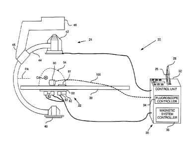
Fig. 1 is a schematic diagram illustrating a
fluoroscopic image and magnetic mapping integration
system 20 in a calibration phase, according to an
embodiment of the present invention. System 20 combines a
three-dimensional (3D) map of a body organ that is
acquired by a magnetic tracking system 22, with a two-
dimensional (2D) fluoroscopic image of the patient
acquired by a fluoroscope 24, so forming a combined
display 26 that is presented to an operator of system 20
on a screen 28. In the calibration phase for system 20
illustrated in Fig. 1 the patient is not present. In a
subsequent operational phase of system 20, illustrated in
Fig. 5, the patient is assumed to be lying on a table 30
of system 20, and magnetic tracking system 22 and
fluoroscope 24 acquire the 3D map and 2D image of the
patient, as described in more detail below. Typically the
2D image acquired by the fluoroscope is of the chest of
the patient, and the body organ mapped by the magnetic
tracking system comprises the heart of the patient.
While in practice system 22 and system 24 may
typically be configured as separate physical units with
separate control units, in the present description, for
simplicity, system 20 is assumed to be operated by a
single control unit 32.
Control unit 32 comprises a fluoroscope controller
34 operating the fluoroscope, and a magnetic system
8
CA 2830552 2019-10-03
controller 36 operating the magnetic tracking system, and
the unit is under overall control of a system processor
38, the processor, inter alia, generating combined
display 26 on screen 28. Software for processor 38 may be
downloaded to the processor in electronic form, over a
network, for example, or it may, alternatively or
additionally, be provided and/or stored on non-transitory
tangible computer-readable media, such as magnetic,
optical, or electronic memory.
Fluoroscope 24 comprises an X-ray source 40 and a
detector 42, the radiator and detector being mounted on
opposite ends of a C-arm 44, assumed herein to comprise
an arc of a circle. C-arm 44 is typically held at a lower
end 45 of an L-arm 46, the L-arm being attached at its
upper end to a ceiling of an operating theater, or at its
lower end to the operating theater floor. C-arm 44 may be
rotated around a horizontal pivot axis PA, which in the
diagram is in the plane of the paper. C-arm 44 may also
rotate around a C-arm axis CA, which is perpendicular to
the plane of the paper and which passes through the
center of the C-arm circle. Nominally, the two axes
intersect at the C-arm center of rotation, also termed
the iso-center, and are orthogonal to each other. The
operator of system 20 is able to adjust rotations of
fluoroscope 24 about axes PA and CA, as well as other
geometrical parameters of the fluoroscope, using
fluoroscope controller 34. (As described in more detail
below, the calibration phase provides adjustments to
nominal properties of fluoroscope 24, such as the ones
exemplified above.)
Magnetic tracking system 22 comprises a location pad
50, which typically has three sets 52 of generally
9
CA 2830552 2019-10-03
similar coils fixedly mounted on the pad. Each set 52 of
coils typically comprises three orthogonally oriented
coils, so that there are a total of nine coils fixedly
attached to pad 50. Pad 50 is fixedly attached to the
underside of table 30, and the coils, under control of
magnetic system controller 36, transmit alternating
magnetic fields into a region 54 in proximity to the pad
and above the bed. In order to track an entity in region
54, herein assumed to comprise a catheter, one or more
coils are attached to the catheter.
The one or more catheter coils generate signals in
response to the magnetic fields received by the coils,
and controller 36 acquires the signals from the coils,
and processes the signals in order to determine a
position of the catheter coils with respect to location
pad 50. A system similar to magnetic tracking system 22
is the CartoTM system produced by Biosense Webster Inc.,
of Diamond Bar, CA. In addition to tracking objects, such
as catheters, magnetic tracking system 22 may be used to
generate the 3D map of the body organ, or of a parameter
related to the body organ. For example, system 22 may
generate a 3D map of electropotentials on the surface of
the heart of the patient, as is described for example, in
U.S. Patent 6,400,981 to Govari.
In order to register the coordinate systems, or
frames of reference, of magnetic tracking system 22 and
fluoroscope system 24, system 20, in its calibration
phase, uses one or more registration elements. A given
registration element has the property that its location
and orientation may be determined simultaneously in both
coordinate systems. Embodiments of the present invention
CA 2830552 2019-10-03
use as a first registration element a helix calibration
jig 60, and as a second registration element a location
pad registration module 62. Helix calibration jig 60,
also referred to herein as jig 60, is described in more
detail with reference to Fig. 2. Registration module 62
is described in more detail with reference to Fig. 3.
In addition to the magnetic tracking coordinate
system and the fluoroscope 'coordinate system, referred to
above, a coordinate system based on location pad 50, and
one based on registration module 62, are present in
system 20. These systems, as is described in more detail
below, are used as intermediaries in the registration of
the magnetic tracking and the fluoroscope coordinate
systems.
Fig. 2 is a schematic perspective diagram of helix
calibration jig 60, according to an embodiment of the
present invention. As will be apparent from the following
description, jig 60 is "visible" in the fluoroscope
system, to an extent that its position therein can be
determined; in addition, the jig is trackable in the
magnetic system so that its position in the magnetic
tracking system is known. Jig 60 is formed as a plastic
cylinder 70 which may be placed, using attached supports
72, on table 30, so that the axis of the cylinder is
parallel to the table. Cylinder 70 has metal spheres 74
embedded in the cylinder. Metal spheres 74 provide good
contrast fluoroscopic images of the spheres in jig 60 at
detector 42. Spheres 74 are arranged in a helical pattern
76 within the cylinder, the helical pattern being
configured to have a varying period length. In addition,
within each period there is a different number of
spheres. The helical pattern is illustrated by broken
11
CA 2830552 2019-10-03
lines connecting spheres 74 of the helix.
In a disclosed embodiment of the present invention
cylinder 70 has an approximate diameter of 120 mm, and an
overall length of helical pattern 76 is approximately 200
mm. In the disclosed embodiment spheres 74 are arranged
to define six periods, and Table I below gives exemplary
lengths of each period in a direction parallel to an axis
of cylinder 70, as well as exemplary numbers of spheres
74 within each period. Typically, spheres 74 are
distributed evenly within each period.
Helix period Number of
length [mm] spheres 72 in
the period
7
11
15
19
23
27
Table I
Further spheres 74 may be added to those of helical
15 pattern 76. For example, more spheres 74 have been added
to form straight lines 78 and 80 of spheres, line 78
corresponding to terminations of the helical periods,
line 80 corresponding to the mid-points of the periods.
The different lengths of the helical pattern
20 periods, together with the different numbers of spheres
74 in each period, enable fluoroscope controller 34 to
uniquely identify each sphere 74. Adding further spheres
to the helical pattern, as described above, further
12
CA 2830552 2019-10-03
facilitates controller 34 in identifying spheres 74. The
identification of spheres 74 is used in registering the
magnetic system with the fluoroscope, as described below.
In some embodiments cylinder 70 comprises retro-
reflectors 90 wherein removable balls 92 may be
positioned. Typically the retro-reflectors are arranged
symmetrically in cylinder 70, in a plane parallel to
table 30 and may be used, with the aid of a laser for
tracking the position of jig 60 on table 30. In an
alternative embodiment, other metal spheres, generally
similar to spheres 74, may be added to jig 60 to further
aid in its positioning.
In addition to having metal spheres 74 embedded in
cylinder 70, the cylinder is also configured to be able
to have a number of magnetic sensors 82 fixedly attached,
at known locations and with known orientations, to the
cylinder. By way of example, there are six sensors 82
which may be attached to cylinder 70. Each sensor 82
typically comprises a set of three orthogonal coils, so
that each sensor 82 is generally similar to a set 52 of
coils in location pad 50. However, in other embodiments
sensor 82 comprises fewer than three coils, and/or may
comprise a magnetic detector such as a Hall detector,
rather than coils.
Cylinder 70 also comprises a catheter holder 94.
Holder 94 enables a catheter 96, having a magnetic sensor
similar to sensor 82, to be fixedly positioned at a
predefined location and with a predefined orientation
with respect to cylinder 70. Connections from the sensor
of the catheter, to magnetic system controller 36 are
routed through the catheter. Connections 100 from sensors
82 are also coupled to the magnetic system controller, as
13
CA 2830552 2019-10-03
is illustrated in Fig. 1.
Fig. 3 is a schematic perspective diagram of
registration module 62, according to an embodiment of the
present invention. In contrast to jig 60, module 62 does
not have magnetic sensors, and so is not trackable in the
magnetic tracking system, and the position of the module
with respect to location pad 50 cannot be determined by
magnetic measurements. Rather, module 62 is configured to
be fixedly connected in a known location and orientation
with respect to the location pad. The fixed connection is
typically accomplished by bolting the module, having
predetermined mechanical measurements, to location pad
50. The fixed connection of module 62 to location pad 50
enables the location and orientation of the module in the
magnetic tracking system to be known.
As for jig 60, module 62 comprises radiopaque
markers 102, similar to spheres 74, which are
incorporated in predefined patterns into two radio-
transparent plates 104 and 106. Plates 104 and 106 are
parallel to each other and are separated by a fixed
distance defined by connectors 108 joining the two
plates. In a disclosed embodiment the markers are
distributed symmetrically about a line of symmetry LOS
defined by the plates. Bolts (not shown) for connecting
the module to the location pad may traverse connectors
108. In addition to markers 102, module 62 comprises a
radiopaque disk 110 embedded into plate 104. In the
disclosed embodiment, a center of disk 110 lies on the
line of symmetry LOS, and the disk is oriented
orthogonally to the line. Typically the location of disk
110, and the distortion of its shape (from round to
elliptical) in a fluoroscopic image acquired by detector
14
CA 2830552 2019-10-03
42 enables fluoroscope controller 34 to accurately
determine the location and orientation of the module in
the fluoroscope system. An advantage of the design of
module 62 is that the fluoroscopic image can accurately
determine the location and orientation of the module even
when not all markers 102 are visible in the fluoroscopic
image. In an alternative embodiment disk 110 may be
replaced by any predetermined 2D shape, typically
symmetrical, such as a rectangle.
In order to operate system 20, the system is
calibrated without the presence of a patient on table 30.
The processes involved in the calibration are described
in the flowcharts of Figs. 4 and 5 below.
Fig. 4 is a flowchart 200 of steps to model
parameters of fluoroscope system 24, according to an
embodiment of the present invention. The model generated
by the flowchart provides a function that is able to
predict the image acquired by detector 42 of an object in
a known position in the fluoroscope coordinate system.
The model may also generate an inverse function, i.e.,
one that may be able to predict the position of an object
in the fluoroscope coordinate system from the object's
image, as acquired by detector 42.
For clarity, in the following description the
fluoroscope coordinate system is assumed to comprise a
set of xyz orthogonal axes that are fixed to C-arm 44 and
that are based on pivot axis PA and C-arm axis CA (Fig.
1). The orientations of the axes are assumed to be as
follows:
A z-axis is orthogonal to the CA and PA axes;
An x-axis is parallel to the CA axis; and
A y-axis is orthogonal to the x and z axes.
CA 2830552 2019-10-03
An origin for the axes may be assumed to be the
projection of the PA axis onto the CA axis in z-axis
orientation, although any other convenient origin may be
used.
It will be understood that the definition of the
above set of axes for the fluoroscope coordinate system
is by way of example, and that other sets of axes will be
apparent to those having ordinary skill in the art. All
such sets of axes are assumed to be comprised within the
scope of the present invention.
The model provided by the flowchart calibrates for
differences from nominal values of geometric parameters
of the fluoroscope, as well as differences from nominal
relationships between the parameters. Some examples of
elements calibrated for in the model are provided in
Table II:
Possible differences from nominal values of
fluoroscope geometric parameters
Actual rotations of C-arm 44 about axis CA,
and/or about axis PA, may be different from those
assumed by fluoroscope controller 34.
The CA and PA axes may not be orthogonal, and/or
may not intersect.
A distance from source 40 to detector 42 may be
different from that assumed by controller 34.
A line from source 40 to the center of detector
42 may not pass through the center of rotation.
Table II
Geometric parameters other than those exemplified in
Table II are calibrated for in the process of flowchart
16
CA 2830552 2019-10-03
200, and such parameters will be apparent to those having
ordinary skill in the art.
In an initial step 202, with neither location pad 50
nor registration module 62 present, jig 60 is placed on
table 30 so that it is approximately on a line between
source 40 and detector 42. The placement may be checked
by using retro-reflectors 90, and using an image acquired
by the detector to confirm correct placement. In the
initial step, jig 60 is in an arbitrary position with
respect to the fluoroscope coordinate system axes
described above.
In a C-arm calibration step 204, the C-arm is
rotated about axes CA and PA, by the fluoroscope
controller, to various pre-defined orientations. In each
orientation detector 42 acquires an image of spheres 74
in jig 60. Fluoroscope controller 34 may also apply other
pre-defined movements to the C-arm, or its components.
For example, detector 42 may be rotated about an axis
orthogonal to the plane of the detector. For each pre-
defined orientation or movement, detector 42 acquires an
image of jig 60.
In a table calibration step 206, jig 60 may be
removed, and a calibration element 61 (Fig. 1), herein
assumed to comprise a ruler, having radiopaque markings
is placed on table 30. The ruler is oriented at a known
angle to the table, typically approximately parallel or
approximately orthogonal to a line of symmetry of the
table, so that an image acquired by detector 42 comprises
an image of the ruler. For a selected orientation of axes
CA and PA, typically an orientation where the rotations
about the axes are nominally zero, fluoroscope controller
34 moves table 30 by predefined translations and
17
CA 2830552 2019-10-03
rotations. After each movement detector 42 acquires an
image of the ruler. The predefined translations are
typically parallel to a length of the table, at right
angles to the length, and orthogonal to a plane of the
table. The rotations may be rotations around axes defined
by the translations.
The translations and orientations applied in steps
204 and 206 move jig 60 or the ruler within the
fluoroscope coordinate system, from their initial
arbitrary location and orientations. Since, during steps
204 and 206 jig 60 and the ruler do not move relative to
table 30, it is only the translations and orientations of
fluoroscope 24, which are known, which alter the position
of the jig and the ruler within the fluoroscope
coordinate system.
Consequently, in a final fluoroscope modeling step
208, controller 34 is able to use the images acquired in
steps 204 and 206, together with the values of the
respective fluoroscope translations and orientations that
are known for each image, to model a relationship between
a fluoroscope projection function and geometric
parameters used in steps 204 and steps 206, i.e., the
motions of the fluoroscope and the motions of the table.
The model relationship enables a prediction to be made by
fluoroscope controller 34, assuming that an object is in
a given location and orientation in the fluoroscope
coordinate system, of an image of the object on detector
42. The model also enables controller 34 to determine the
location and orientation of an object imaged by detector
42 from the image acquired by the detector. The
determination is used to perform registration between the
fluoroscope coordinate system and a location pad
18
CA 2830552 2019-10-03
coordinate system based on a registration image.
Consideration of steps 202 - 208 shows that the
model relationship generated in step 208 does not use
magnetic measurements. Furthermore, the model only relies
on the invariance of the radiopaque elements in the jig
and the ruler, and on the fact that neither the jig nor
the ruler move on table 30 during the operations
performed in the steps.
Fig. 5 is a flowchart 300 of steps to register the
magnetic tracking coordinate system with the fluoroscope
coordinate system, according to an embodiment of the
present invention. In the description of flowchart 300,
it is assumed that flowchart 200 has already been
performed, and that the model relationship has been
generated.
Tn an initial step 302, the magnetic tracking
coordinate system is registered with a mechanical
coordinate system defined by the mechanical structure of
location pad 50, herein termed the location pad
coordinate system. The registration is typically
performed prior to installation of the location pad into
system 20, and may be performed on production of the
location pad. The registration typically involves
defining a location pad coordinate system in terms of the
locations of the three sets 52 of coils comprising the
location pad, measuring the location and orientation of a
sensor coil, typically in a catheter, with respect to the
location pad coordinate system, and relating signals from
the sensor coil to the measured location and orientation.
The registration performed in this step is a nominal
registration, and corrections may be made to this nominal
registration in later steps of the flowchart.
19
CA 2830552 2019-10-03
In a registration module attachment step 304, module
62 is physically attached to location pad 50, as
described above. The physical attachment is typically
performed prior to installation of the location pad and
its attached registration module 62 into system 20. The
physical attachment aligns the registration module into a
predefined nominal location and orientation with respect
to the location pad, so that a coordinate system based on
the registration module, termed the registration module
coordinate system, may be nominally registered with the
location pad coordinate system. The nominal registration
provided for in this step may also be corrected for in
later steps of the flowchart.
In a registration step 306, the combined location
pad and registration module is inserted, as a single
unit, under table 30, and is fixedly attached to the
table. In addition jig 60 is positioned on the table,
above the registration module, and the table is moved so
that the image acquired by detector 42 includes the
images of the radiopaque elements of the registration
module and of the jig.
Magnetic sensors 82 are fixed to jig 60, in their
known locations and orientations, and the coils in the
location pad are energized. Signals from the sensors,
generated in response to the magnetic field radiated by
the location pad coils, are received by magnetic system
controller 36, and the controller analyzes the signals to
determine a location and an orientation for the jig in
the magnetic coordinate system.
Simultaneously, fluoroscope controller 34 analyzes
the image acquired by detector 42 and, using the model
generated in flowchart 200, determines a location and an
CA 2830552 2019-10-03
orientation of jig 60 in the fluoroscope coordinate
system.
Typically, as illustrated by an arrow 310, jig 60 is
moved into other positions, by moving the jig on table
30, and/or by moving table 30. For each new position of
the jig, locations and orientations of the jig in both
coordinate systems are determined by controllers 34 and
36. The images acquired for the multiple jig positions of
this step increase the accuracy of the transformation
generated in the following step.
In a transformation generation step 312, system
processor 38 receives the results of the locations and
orientations of the jig in the two coordinate systems, in
the multiple positions set in step 306. Processor 38 uses
the results to generate a transformation [TI] between the
two coordinate systems. Processor 38 may check the
accuracy of transformation [TI], and adjust values of
elements of the transformation, by using other magnetic
sensors in known positions. For example, catheter 96
(with a magnetic sensor) may be inserted into holder 94
(Fig. 2), and the commonality of the catheter positions
as measured in the two systems may be verified.
In a final step 314, processor 38 assumes that
transformation [TI] is a composition of two sub-
transformations, according to equation (1):
[Tmodule,fluoro] * [Tmagnetic,module] = (1)
where ET
module,fluord is a transformation between the
fluoroscope coordinate system and a coordinate system
defined by the registration module, and
rrinagmeticmwdule] is a transformation between the
21
CA 2830552 2019-10-03
registration module coordinate system and the magnetic
coordinate system.
The location and orientation of the registration
module in the fluoroscope coordinate system are known
from the images of the module acquired by detector 42,
and these enable processor 38 to evaluate rr
module,fluord =
While nominal location and orientation coordinates of the
module in the magnetic coordinate system are known, (so
that transformation rrinag nedmoduld is nominally known)
deviations from specification in the mounting of the
registration module to the location pad cause deviations
from the nominal values. Processor 38 consequently
applies equation (1), where transformations pm and
[T-module,fluoro] are known, to find an actual expression for
transformation [r
magnetic,module] = This expression is used in
an operational phase of system 20, as is explained below.
Fig. 6 is a schematic diagram illustrating system 20
in an operational phase, according to an embodiment of
the present invention. Apart from the differences
described below, the operation of system 20 in its
operational phase is generally similar to that of the
system in its calibration phase, and elements indicated
by the same reference numerals in both Fig. 1 and Fig. 6
are generally similar in construction and in operation.
During the operational phase, jig 60 is removed, a
patient 400 is positioned on table 30, and a catheter 402
with a magnetic sensor is inserted into the patient so
that the sensor is in region 54. By way of example, the
patient is assumed to be positioned in a head first
supine (HFS) orientation. Positioning the patient on the
22
CA 2830552 2019-10-03
table may move the table, and its attached location pad
50 and registration module 62, from its calibration phase
state, so that the magnetic coordinate system of the
fields generated by the location pad may no longer be in
the registration with the fluoroscope coordinate system
achieved by the steps of flowchart 300. Other changes
from the calibration phase may occur, such as movement of
table 30, and/or movement of the location pad with
respect to the table, so that the transformation [TI]
generated in step 314 may no longer be correct.
Embodiments of the present invention use an image of
registration module 62 to ' re-register the magnetic
coordinate system with the fluoroscope coordinate system,
as is described in more detail below with regard to a
flowchart 500 of Fig. 7.
Fig. 7 shows flowchart 500 of steps for combining a
magnetic tracking coordinate system map with a
fluoroscope coordinate system image, according to an
embodiment of the present invention. In the description
of flowchart 500, it is assumed that the steps of
flowcharts 200 and 300 have already been performed. The
steps of flowchart 500 correspond to the operational
phase of system 20. In contrast to the calibration phase
of the system, wherein no patient is present, in the
operational phase a patient is present, so that X-ray
exposure of the patient should be minimized.
In an initial step 502, patient 400 is positioned on
table 30. As described above, positioning the patient on
the table alters the physical position of the location
pad from the position used in finding transformation
[Ti], so that the registration between the two systems
has changed, and so that the transformation may no longer
23
CA 2830552 2019-10-03
apply accurately.
To compensate for the change of location pad
physical position, in an imaging step 504 a single image
of the registration module is acquired by detector 42 in
the fluoroscope system. While the position in the
fluoroscope system of the registration module has
changed, the position of the module within the magnetic
coordinate system, as determined in step 314 of flowchart
300, has not changed, since the registration module is
physically connected to the location pad. In other words,
transformation [rIna gneticxmduld is still valid.
In a re-registration step 506 processor 38 uses the
image acquired in step 504 to calculate an updated
transformation between the fluoroscope system and the
registration module: rrmodulefluoronew] . The processor then
applies the updated transformation, in order to calculate
a transformation [T2] (which is an updated transformation
[T1]), according to equation (2):
[Tmodule,fluoro,new] * [Tmagnetic,module] = [T2] (2)
Equation (2) is also applied, by finding new values
of [Tmodule,fluoro,new] for every movement of table 30
(causing the location pad to move). The new values are
based on the table calibration results determined in
table calibration step 206 of flowchart 200.
In a display generation step 508 processor 38 uses
transformation [T2] to register elements having positions
determined in the two systems, and to present the
resultant combined image on screen 28 as an overlay of a
24
CA 2830552 2019-10-03
fluoroscope coordinate system image on a magnetic
coordinate system map. The method for combining the image
and the map takes account of different methods typically
used for generating the image and the map in each system,
as described below with reference to Fig. 8. The method
for combining the image with the map may typically also
be dependent on the elements present in the image and the
map.
Fig. 8 is a schematic diagram illustrating methods
for combining the image and the map of Fig. 7, according
to an embodiment of the present invention. Source 40 acts
as a point source of X-rays, which radiate through a
"pyramid" 600, so that in the fluoroscope system the 2D
image acquired by detector 42 of a 3D volume of interest
601 in the pyramid corresponds to a perspective
projection, where the source acts as the origin of the
projection, and wherein projection lines (not shown on
the diagram) radiate from the source to the detector.
However, the 2D display of the 3D volume of interest, as
presented in the magnetic system, is typically different
from a perspective projection. For example, in the Carto
system referred to above, wherein the volume of interest
is the heart, a 3D electropotential map of the heart is
typically provided on screen 28 as an orthographic
projection, wherein projection lines through the heart
are parallel to each other.
Embodiments of the present invention allow an
operator of system 20 to select an effective "plane" 602,
parallel to detector 42, within pyramid 600 which is to
be used for aligning and positioning the perspective
projection in the fluoroscope system with the
orthographic projection in the magnetic system. The plane
CA 2830552 2019-10-03
selected is a plane within the 3D volume of interest.
Three examples of the planes, assuming that the volume of
interest corresponds to a heart electropotential map, are
shown in the figure, although other planes may be used. A
plane 602A is a plane through a center of gravity of the
electropotential map; a plane 602B is a plane through an
item of interest 604 in the map; and a plane 602C is a
plane through a center of rotation COR of the fluoroscope
system, as projected onto the map. Selection of the
different planes is effected by deciding on a point in
the image and in the map that is to correspond, and then
adjusting a magnification of the perspective projection.
The magnetic system typically determines both the
location and orientation of catheters that are tracked by
the system. Thus, for example, if item of interest 604
corresponds to the distal tip of a catheter, an icon of
the catheter may be used in the combined display
presented on screen 28, and the icon image may be varied
to represent both the location and orientation of the
catheter.
The description above has assumed that the
perspective projection of the fluoroscope system is
incorporated into the orthographic projection of the
magnetic system. However, the description may be applied,
mutatis mutandis, to converting the orthographic
projection of the magnetic system into a perspective
projection. The perspective projection of the fluoroscope
system may then be incorporated into the magnetic
perspective projection.
Returning to image generation step 508 (Fig. 7),
once transformation [T2) has been formulated, the
transformation may be applied for substantially any
26
CA 2830552 2019-10-03
display on screen 28 that is desired by the system
operator. Furthermore, the transformation may be applied
completely automatically for the chosen display, and may
be applied to real-time imaging as well as to stored
images.
Typically, processor 38 may import and store every
image generated by the fluoroscope. The processor may
then process the fluoroscopic image to derive the desired
image plane coordinates (in the magnetic system), and
store the image along with these coordinates. This image
can then be viewed aligned and in overlay with the
magnetic system map.
Similarly, when the operator rotates the magnetic
system map to see a different view, and this view angle
corresponds to a projection angle at which a fluoroscopic
image was previously captured and stored, the processor
may recall the corresponding image automatically and
display it together with the map.
Alternatively or
additionally, if no fluoroscopic image has been acquired
and stored at the current map viewing angle, processor 38
may automatically instruct the fluoroscope to acquire an
image for display together with the magnetic system map
at this angle.
As a further option, the operator can set the
magnetic mapping system so that upon acquiring a
fluoroscopic image at a certain angle (or displaying a
previously-acquired image), processor 38 automatically
rotates the magnetic system map so that the projection
angle of the map matches that of the fluoroscopic image.
This technique ensures that the magnetic system map
projection and the fluoroscopic projection that are
displayed at any time are in proper registration and
27
CA 2830552 2019-10-03
helps to prevent operator errors in carrying out the
procedure.
The technique described above can be used not only
to import and register entire fluoroscopic images into
the magnetic mapping system, but also to import and
register particular objects - such as particular
anatomical structures and features - that may be
segmented in a fluoroscopic image. Based on registration
of the fluoroscopic image from which the object is taken,
each such object will have a location and orientation in
the magnetic coordinate system. An object
selected by
the user can thus be registered and superimposed on the
magnetic map with little or no user involvement in the
actual registration process.
The processor can also invert the fluoroscopic image
by 1800. For example, when the fluoroscopic image is taken
in HFS view, and the orientation of the magnetic system
map is also HFS, the fluoroscopic image may be displayed
on the magnetic system map. If the magnetic system map
orientation is inverted, on the other hand, the processor
can invert the fluoroscopic image from the HFS view, and
thus continue to display the fluoroscopic image in proper
registration with the magnetic system image. In treating
atrial fibrillation, for example, the operator usually
sets the magnetic system orientation inverted from the
HFS view, in order to see the veins while ablating. With
the inverted view, the operator will also be able to see
also the fluoroscopic image in the inverted view, even
when the fluoroscope itself is unable to actually capture
images in this orientation.
The ability of the system to register fluoroscopic
images with the magnetic system map, and to present
28
CA 2830552 2019-10-03
correctly the appropriate fluoroscopic image at each
angle of projection of the magnetic system map, can be
used in various other ways to enhance visualization
during catheterization procedures. For example, the
magnetic system map may be rotated and corresponding
fluoroscopic images may be displayed in order to enable
the operator to verify the distance between the arteries
and the catheter tip.
Fluoroscopic images that have been registered with
the magnetic system map can also be used to assist in
aligning and registering other images, such as CT
(computerized tomography) or MRI (magnetic resonance
imaging) images, with the magnetic system map.
Registration of fluoroscopic images with magnetic
maps in the manner described above can be useful in
reducing the X-Ray dosage to which patients are exposed.
For example, the operator may be able to carry out
catheter insertion without simultaneous X-Ray imaging by
using pre-acquired, registered fluoroscopic images.
Similarly, a pair of pre-acquired, registered
fluoroscopic images from different angles can be used to
assist the operator in inserting a catheter at a certain
location (such as the coronary sinus) based on the
magnetic map without requiring simultaneous X-Ray
imaging. Fluoroscopic cine loops can also be registered
in the manner described above and then played back in
proper registration during magnetic mapping and
treatment.
It will be appreciated that the embodiments
described above are cited by way of example, and that the
present invention is not limited to what has been
particularly shown and described hereinabove. Rather,
29
CA 2830552 2019-10-03
the scope of the present invention includes both
combinations and subcombinations of the various features
described hereinabove, as well as variations and
modifications thereof which would occur to persons
skilled in the art upon reading the foregoing description
and which are not disclosed in the prior art.
CA 2830552 2019-10-03