Note: Descriptions are shown in the official language in which they were submitted.
CA 02830702 2013-10-23
APPARATUS AND METHOD FOR SERVICING PIPES
[0001]
[0002]
BACKGROUND
[0003] The present disclosure relates generally to drilling of wells. More
particularly, the
present disclosure relates to methods and apparatus for cleaning, lubricating
and testing pipes.
[0004] At some point during the drilling of a well, there will be a reason to
pull a drill string
out of a well and then run it back in. This process is typically referred to
as "tripping." The
portion of the tripping involving pulling the drill string out of the well may
be referred to as
"tripping out," and the portion of the tripping involving running the drill
string back into the well
,
may be referred to as "tripping in." Tripping out involves breaking out pipe
connections, whereas
tripping in involves making up pipe connections. On some rigs, the breaking
out and making up
of pipe connections are between single drill pipes, as opposed to pipe stands,
and a drill string.
[0005] During tripping out, the drill string is suspended in the well in
slips. An elevator picks
the drill string up from the slips and raises the drill string until a drill
pipe at the top of the drill
string is just above the slips. The slips then close. An iron roughneck is
used to spin the drill pipe
and break out the connection between the drill pipe and the drill string. A
pipe handling system
picks up the drill pipe, disconnecting the elevator from the drill pipe. The
pipe handling system
moves the drill pipe to a horizontal position on the ground. A forklift then
picks the drill pipe
from the pipe handling system and places the drill pipe in a horizontal rack
on the ground. This
process can be repeated for as many drill pipes as need to be separated from
the drill string. The
separated drill pipes can be arranged in multiple horizontal racks on the
ground.
[0006] Tripping in starts with the drill pipes stored in horizontal racks on
the ground. While the
drill string is suspended in slips, a worker lubricates a box at the top of
the drill string. A forklift
moves a drill pipe from one of the horizontal racks to the pipe handling
system, and the pipe
handling system in turn moves the drill pipe to the well center. At the well
center, an elevator
picks up the drill pipe and stabs the drill pipe into the box. After the
stabbing, an iron roughneck
spins the drill pipe and makes up the connection between the drill pipe and
the drill string. The
elevator then lifts the drill string from the slips and lowers the drill
string until the drill pipe is
1
CA 02830702 2013-10-23
just above the slips. The slips close, and the elevator is disconnected from
the drill pipe. This
process can be repeated for as many drill pipes as need to be connected to the
drill string.
[0007] In some cases, prior to connecting a drill pipe to the drill string,
the pin and box of the
drill pipe are cleaned. Typically, this cleaning is carried out while the
drill pipe is in the vertical
position. The cleaning of the drill pipe and lubrication of the box prior to
making up the pipe
connection lengthen the duration of the tripping in. Also, the vertical
orientation of the drill pipe
during the cleaning as well as time constraints on rig operations can make it
difficult to achieve
quality pipe cleaning and lubrication.
BRIEF SUMMARY OF THE DISCLOSURE
[0008] The present disclosure describes embodiments of apparatuses and methods
for servicing
pipes. In an embodiment, an apparatus for servicing pipes includes a pipe
holder having a
frame configured to support the pipe and a movement assembly coupled to the
frame and
configured to rotate the pipe about a longitudinal axis of the pipe, a first
pipe servicing tool
disposed proximate to an end of the pipe holder, wherein the first pipe
servicing tool is
configured to operably engage an end of the pipe when the pipe is rotated by
the movement
assembly. In this embodiment, the apparatus may also include an actuator
coupled to the pipe
holder and configured to selectively move the pipe holder between a horizontal
position and an
inclined position. The first pipe servicing tool may include a cleaning tool
configured to deliver a
cleaning fluid to an end of the pipe. The first pipe servicing tool may also
include a lubrication
tool configured to deliver lubricant to an end of the pipe. Further, the first
pipe servicing tool
may include a conductivity tester configured to test the conductivity of a
conductor of the pipe.
[0009] In this embodiment, the first pipe servicing tool include a combination
tool configured
to lubricate the pipe and test the conductivity of a conductor of the pipe.
The cleaning tool may
include a nozzle coupled to an end of a retractable arm, wherein the nozzle is
configured to apply
a fluid to a surface of the pipe and an actuator coupled to the arm and
configured to extend and
retract the arm. The conductivity tester may include an actuator coupled to a
retractable shaft and
configured to extend and retract the shaft, a conductor coupled to an end of
the shaft and
configured to engage a conductor of the pipe and a shield configured to
protect the conductivity
tester from a collision with the pipe. The shield may be rotatable between a
first position and a
second position, wherein in the first position the shield is arranged to
contact the pipe and
wherein in the second position the shield is arranged to allow the conductor
to engage the pipe.
2
CA 02830702 2013-10-23
The combination tool may include a rotary actuator coupled to a first end of a
shaft, wherein the
actuator is configured to rotate the shaft, a conductor coupled to a second
end of the shaft,
wherein the conductor is configured to contact a conductor of the pipe and an
electrical lead
connected to the annular conductor and extending through the conduit of the
shaft. Also, this
embodiment may further include a second pipe servicing tool disposed proximal
to the opposite
end of the pipe from the first pipe servicing tool. The second pipe servicing
tool may be selected
from the group including of a cleaning tool, a lubrication tool and a
combination tool.
[0010] In another embodiment, an apparatus for servicing pipes includes a pipe
holder
comprising, a frame configured to support the pipe and a movement assembly
coupled to the
frame configured to manipulate the pipe, and a first pipe servicing tool
disposed proximate to an
end of the pipe holder and configured to operably engage an end of the pipe,
wherein the first
pipe servicing tool and the movement assembly are configured to provide
relative movement
between the first pipe servicing tool and the pipe. The first pipe servicing
tool and the movement
assembly may be configured to provide relative rotational movement between the
first pipe
servicing tool and the pipe. The first pipe servicing tool and the movement
assembly may also
configured to provide relative axial movement between the first pipe servicing
tool and the pipe.
This embodiment may further include an actuator coupled to the pipe holder and
configured to
selectively move the pipe holder between a horizontal position and an inclined
position.
[0011] In this embodiment, the first pipe servicing tool may include a
conductivity tester
configured to test the conductivity of a conductor of the pipe. The first pipe
servicing tool may
also include a combination tool configured to lubricate the pipe and test the
conductivity of a
conductor of the pipe. The cleaning tool may include a nozzle coupled to an
end of a retractable
arm, wherein the nozzle is configured to apply a fluid to a surface of the
pipe and an actuator
coupled to the arm and configured to extend and retract the arm. The
conductivity tester may
include an actuator coupled to a retractable shaft and configured to extend
and retract the shaft, a
conductor coupled to an end of the shaft and configured to engage a conductor
of the pipe and a
shield configured to protect the conductivity tester from a collision with the
pipe. The shield may
be rotatable between a first position and a second position, wherein in the
first position the shield
is arranged to contact the pipe and wherein in the second position the shield
is arranged to allow
the conductor to engage the pipe. Also, the combination tool may include a
rotary actuator
coupled to a first end of a shaft, wherein the actuator is configured to
rotate the shaft, a conductor
3
CA 02830702 2013-10-23
coupled to a second end of the shaft, wherein the conductor is configured to
contact a conductor
of the pipe and an electrical lead connected to the annular conductor and
extending through the
conduit of the shaft.
[0012] In another embodiment, a method for servicing pipes includes supporting
a pipe in one
of a horizontal position and an inclined position, disposing a pipe servicing
tool proximal to an
end of the pipe and operating the pipe servicing tool to perform a servicing
at an end of the pipe,
the servicing being selected from the group consisting of delivering cleaning
fluid to the end of
the pipe, delivering lubricant to the end of the pipe and testing the
conductivity of a conductor of
the pipe. This embodiment may also include transferring a pipe from a pipe
storage system to a
roller assembly via pivoting the pipe storage system relative to the roller
assembly.
[0013] In another embodiment, an apparatus includes a pipe holder configured
to support and
rotate a pipe about an axis of the pipe. This embodiment also includes one or
more pipe servicing
tools disposed proximate to one or both of the ends of the pipe holder. The
one or more pipe
servicing tools may include a cleaning tool configured to deliver cleaning
fluid to an end of the
pipe, a lubrication tool configured to deliver lubricant to an end of a pipe
and a conductivity
tester tool configured to test the conductivity of a conductor. This
embodiment further includes
an actuator for selectively moving the pipe holder between a horizontal
position and an inclined
position.
[0014] In an embodiment, the apparatus further includes at least one
translation device for
moving at least one of the pipe servicing tools relative to the pipe holder
and between a servicing
position and a parking position. Two of the pipe servicing tools may be
disposed proximate to
the same end of the pipe holder and one of the pipe servicing tools is
disposed proximate to a
different end of the pipe holder.
[0015] In an embodiment, the apparatus further includes at least one
translation device for
selectively moving each of the pipe servicing tools disposed proximate to the
same end of the
pipe holder relative to the pipe holder and between a servicing position and a
parking position.
One of the pipe servicing tools may be disposed proximate to the same end of
the pipe holder is a
cleaning tool. The other of the pipe servicing tool may be disposed proximate
to the same end of
the pipe holder is a lubrication tool. Also, one of the pipe servicing tools
may be disposed
proximate to the different end of the pipe holder is a cleaning tool.
4
CA 02830702 2013-10-23
[0016] In an embodiment, at least one of the pipe servicing tools may have a
cavity for
receiving an end of a pipe. The pipe servicing tool having a cavity may be a
cleaning tool, and
the apparatus may further include a reservoir in communication with the cavity
for draining fluid
from the cavity. At least one of the pipe servicing tools may be a cleaning
tool configured to
deliver cleaning fluid through a nozzle. At least one of the pipe servicing
tools may be a cleaning
tool configured to selectively deliver cleaning fluid and drying fluid through
at least one nozzle.
[0017] In an embodiment, the apparatus may further include a mounting base
pivotally coupled
to the pipe holder, and the actuator may be coupled to the pipe holder and the
mounting base and
operable to apply a push or pull force to the pipe holder to move the pipe
holder between the
horizontal and inclined positions. The pipe holder may include a pair of
roller assemblies, and
each of the roller assemblies may include a pair of roller units that are
movable between an open
position and a closed position. Each of the roller units may include a pair of
rollers, and each of
the roller assemblies may further include one or more drive motors for driving
at least one of the
rollers in each roller unit. The pipe holder may include a support arm with a
pair of stands for
mounting the pair of roller assemblies, and at least one of the stands may be
movable to adjust a
position of the roller assembly mounted thereto relative to a length of the
support arm.
[0018] In an embodiment, the apparatus may further include a pair of pipe
storage assemblies
disposed on opposite sides of the pipe holder.
[0019] In an embodiment, the apparatus may further include a pair of pipe
handling assemblies
between the pipe storage assemblies and pipe holder for transferring pipes
between the pipe
storage assemblies and pipe holder.
[0020] In an embodiment, operation of the apparatus may be automated.
[0021] The present disclosure further describes methods of servicing pipes. In
one aspect, a
method includes supporting a pipe in one of a horizontal position and an
inclined position. The
pipe servicing method may further include arranging one or more pipe servicing
tools at a
servicing or parking position relative to one or both ends of the pipe. The
method may further
include operating at least one of the pipe servicing tools to perform a
service at an end of the
pipe, where the service may be selected from the group consisting of
delivering cleaning fluid to
the end of the pipe and delivering lubricant to the end of the pipe. The at
least one pipe service
tool may perform the service of delivering cleaning fluid to the end of the
pipe, and the method
may further include moving the pipe to the inclined position prior to
performing the service of
CA 02830702 2013-10-23
delivering cleaning fluid. The at least one pipe servicing tool may perform
the service of
delivering cleaning fluid to the end of the pipe, and the method may further
include rotating the
pipe during the operation of the at least one pipe servicing tool.
[0022] In an embodiment, the method may further include at least one of
translating the at least
one pipe servicing tool relative to the pipe or translating the pipe relative
to the at least one pipe
servicing tool such that the at least one pipe servicing tool is in a
servicing position. The at least
one pipe servicing tool may have a cavity, and translating the at least one
pipe servicing tool or
pipe is until an end of the pipe is received in the cavity.
[0023] In an embodiment, the method may further include operating two of the
pipe servicing
tools contemporaneously to perform the services of delivering cleaning fluid
to opposite ends of
the pipe.
[0024] In an embodiment, the method may further include moving the pipe to an
inclined
position prior to operating the two of the pipe servicing tools to perform the
services of
delivering cleaning fluid.
[0025] In an embodiment, the method may further include rotating the pipe
during operating
the two of the pipe servicing tools to perform the services of delivering
cleaning. Two of the pipe
servicing tools may be operated to perform the services of delivering cleaning
fluid and lubricant
to the same end of the pipe, and the method may further include sequentially
positioning the two
of the pipe servicing tools at servicing positions at the same end of the
pipe. Two of the pipe
servicing tools may perform the services of delivering cleaning fluid to
opposite ends of the pipe
and one of the pipe servicing tools may perform the service of delivering
lubricant to one of the
ends of the pipe, and the service of delivering lubricant may be performed
after completion of
the services of delivering cleaning fluid.
[0026] In an embodiment, the method may further include moving the pipe to the
inclined
position prior to performing the services of delivering cleaning fluid and
moving the pipe to the
horizontal position prior to performing the service of delivering lubricant.
At least one of the
pipe servicing tools may perform the service of delivering cleaning fluid, and
the method may
further include draining fluid from the at least one of the pipe servicing
tools performing the
service of delivering cleaning fluid into a reservoir.
[0027] In an embodiment, at least one of the pipe servicing tools may perform
the service of
delivering cleaning fluid, and the method may further include operating the at
least one of the
6
CA 02830702 2013-10-23
pipe servicing tools to perform the service of drying an end of the pipe to
which the cleaning
fluid was delivered.
[0028] In an embodiment, the method may further include repeating the
supporting the pipe,
the arranging of the one or more pipe servicing tools, and the operating of
the at least one of the
pipe servicing tools for a plurality of pipes.
[0029] The present disclosure further describes a method of tripping in a
drilling operation. In
one aspect, the method may include separating one or more dirty pipes from a
drill string
suspended in the well and transporting the dirty pipes to an apparatus
configured to clean and/or
lubricate ends of the dirty pipes in a non-vertical position. The method may
further include
operating the apparatus to clean and/or lubricate the dirty pipes and
transporting the clean and/or
lubricated pipes to a storage area for later use.
[0030] It is to be understood that both the foregoing general description and
the following
detailed description are exemplary of the disclosure and are intended to
provide an overview or
framework for understanding the nature and character of the disclosure as it
is claimed. The
accompanying drawings are included to provide a further understanding of the
disclosure and are
incorporated in and constitute a part of this specification. The drawings
illustrate various
embodiments of the disclosure and together with the description serve to
explain the principles
and operation of the disclosure.
BRIEF DESCRIPTION OF THE DRAWINGS
[0031] The following is a description of the figures in the accompanying
drawings. The figures
are not necessarily to scale, and certain features and certain views of the
figures may be shown
exaggerated in scale or in schematic in the interest of clarity and
conciseness.
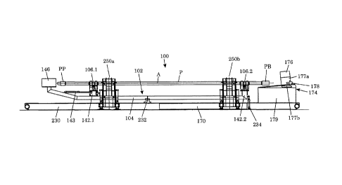
[0032] Fig. 1 is a top view of an apparatus for servicing pipes;
[0033] Fig. 2a shows a roller assembly for engaging and rotating a pipe;
[0034] Fig. 2b shows a top view of the roller assembly of Fig. 2a;
[0035] Fig. 2c shows a roller assembly in a closed position;
[0036] Fig. 3a shows a cleaning tool for a pin before cleaning;
[0037] Fig. 3b shows a cleaning tool for a pin after cleaning;
[0038] Fig. 4a shows a cleaning tool for a box before cleaning;
[0039] Fig. 4b shows a cleaning tool for a box after cleaning;
[0040] Fig. 5 shows a lubrication tool in a servicing position;
7
CA 02830702 2013-10-23
[0041] Fig. 6a shows a pipe being cleaned in an inclined position;
[0042] Fig. 6b shows a pipe being lubricated in a horizontal position;
[0043] Fig. 7 shows an apparatus for servicing pipes with pipe loading and
unloading systems;
[0044] Figs. 8a-8d illustrate a process for loading and unloading pipes from
an apparatus for
servicing pipes;
[0045] Figs. 9a-9e show another embodiment of a cleaning tool of an apparatus
for servicing
pipes in accordance with principles disclosed herein; and
[0046] Figs. 10a and 10b show another embodiment of a lubrication tool of an
apparatus for
servicing pipes in accordance with principles disclosed herein.
DETAILED DESCRIPTION
[0047] In the following detailed description, numerous specific details may be
set forth in order
to provide a thorough understanding of various embodiments of the disclosure.
However, it will
be clear to one skilled in the art when embodiments of the disclosure may be
practiced without
some or all of these specific details. In other instances, well-known features
or processes may not
be described in detail so as not to unnecessarily obscure the disclosure. In
addition, like or
identical reference numerals may be used to identify common or similar
elements.
[0048] An apparatus 100 for servicing pipes is shown in Fig. 1. The apparatus
100 can be used
to clean and/or lubricate pipes. The apparatus 100 includes a pipe holder 102
that supports and
rotates a pipe P about a longitudinal or central pipe axis A. Typically, the
pipe will have a box,
i.e., an internal (female) threaded end, and a pin, i.e., an external (male)
threaded end. The term
"pipe" herein refers to any tubular good that may be used in connection with
performing
operations in an oil or gas well, e.g., drill pipes, drill collars, and
casings.
[0049] In one embodiment, the pipe holder 102 includes a support arm 104 and
two movement
or roller assemblies 106.1, 106.2 mounted in spaced-apart relation on the
support arm 104, where
each roller assembly 106.1 and 106.2 are configured to manipulate the pipe.
The roller
assemblies 106.1, 106.2 are responsible for engaging and rotating the pipe P.
The roller assembly
106.1 will be described in detail below. The roller assembly 106.2 would
typically have the same
structure as, or equivalent structure to, the roller assembly 106.2 and hence
will not be described
in detail separately.
[0050] In one embodiment, as shown in Fig. 2a, the roller assembly 106.1
includes a roller
frame 108.1. The roller assembly 106.1 further includes roller units 110a,
110b mounted on
8
CA 02830702 2013-10-23
opposite sides of the frame 108.1. The roller unit 110a will be described in
detail below. The
roller unit 110b would typically have the same structure as the roller unit
110a and hence will not
be described in detail separately.
[0051] In one embodiment, as shown in Fig. 2a, the roller unit 110a includes
paired rollers
112a, 114a nested between parallel roller arms 116a, 118a (see 118a in Fig.
2b). The rollers
112a, 114a are supported on shafts 120a, 122a, respectively, which are coupled
to the roller arms
116a, 118a, respectively. The rollers 112a, 114a are allowed to rotate on the
shafts 120a, 122a,
respectively. A drive motor 124a (see 124a in Fig. 2b) is coupled to the outer
roller 112a and can
be used to rotate the outer roller 112a on the shaft 120a, while the bottom
roller 114a is allowed
to spin freely on the shaft 122a. Typically, there will be no contact between
the rollers 112a,
114a.
[0052] In one embodiment, lower ends of the roller arms 116a, 118a are coupled
to a shaft
130a, which is arranged to rotate in a bearing 128a disposed between the
roller arms 116a, 118a.
The bearing 128a is integrated with or otherwise attached to the frame 108.1.
By this
arrangement, the roller arms 116a, 118a are pivotally coupled to the frame
108.1. Other methods
of pivotally coupling the roller arms 116a, 118a to the frame 108.1 besides a
shaft and bearing
may be alternately used.
[0053] An actuator 134a is configured to selectively apply a push or pull
force to the roller
arms 116a, 118a (see 118a in Fig. 2b). In one embodiment, one end of the
actuator 134a is
coupled to the upper ends of the roller arms 116a, 118a at a pivot joint 136a,
and another end of
the actuator 134a is coupled to the frame 108.1 at a pivot joint 138a.
Typically, the actuator 134a
will be a linear actuator, such as a fluid-powered cylinder. In general, the
actuator 134a may be
any actuator, linear or otherwise, configured to selectively apply push and
pull forces to the
roller arms 116a, 118a such that the roller arms 116a, 118a pivot on the shaft
130a.
[0054] When the actuator 134a applies a push force to the roller arms 116a,
118a, the roller
unit 110a pivots on the shaft 130a towards the center of the frame 108.1, as
indicated by the
arrow 132. Conversely, when the actuator 134a applies a pull force to the
roller arms 116a, 118a,
the roller unit 110b pivots on the shaft 130a away from the center of the
frame 108.1, as
indicated by the arrow 133. In the embodiment where the actuator 134a is a
linear actuator, the
actuator 134a may apply a push force to the roller unit 110a when extended and
a pull force
when retracted.
9
CA 02830702 2013-10-23
[0055] A mounting roller 140 is supported on the frame 108.1 in a manner that
allows the
roller 140 to rotate relative to the frame 108.1. The roller units 110a, 110b
are disposed on
opposite sides of the frame 108.1 such that the mounting roller 140 is between
the roller units
110a, 110b. The plane in which the rollers 112a, 114a of the roller unit 110a
rotate will generally
be parallel to the plane in which the rollers 112b, 114b of the roller unit
110b rotate. The
mounting roller 140 is configured to rotate in a plane that is transverse to
the planes in which the
rollers of the roller units 110a, 110b rotate. In other words, the mounting
roller 140 is disposed
crosswise relative to the rollers 112a, 114a, 112b, 114b (or the roller units
110a, 110b).
[0056] The roller units 110a, 110b can be rotated outwardly to the open
position, in the
direction shown by the arrow 132, to allow the pipe P to be placed on the
mounting roller 140.
While the roller units 110a, 110b are in the open position, the pipe P can
slide on the mounting
roller 140 and relative to the roller assembly 106.1. This motion can be used
to adjust the
position of the pipe P along the length of the support arm 104 (see 104 in
Fig. 1). The roller units
110a, 110b can be rotated inwardly to the closed position, in the direction
shown by the arrow
133, to engage the outer diameter of the pipe P placed on the mounting roller
140. The actuators
134a, 134b apply the necessary force to rotate the roller units 110a, 110b,
respectively, between
the open and closed positions.
[0057] Fig. 2c shows the roller units 110a, 110b in the closed position, where
the pipe P is
nested between the rollers 112a, 114a and 112b, 114b of the roller units 110a,
110b, respectively.
As part of engaging the pipe P, the roller units 110a, 110b have lifted the
pipe P off the mounting
roller 140. Forces Fl, F2 applied by the actuators 134a, 134b (see 134a, 134b
in Fig. 2a) will
maintain the roller units 110a, 110b in the closed position until it is
desired to release the pipe P.
When the pipe P is nested between the roller units 110a, 110b, the drive
motors 124a, 124b (see
124a, 124b in Fig. 2b) can be operated to rotate the outer rollers 112a, 112b,
which will result in
torque being applied to the pipe P to rotate the pipe P between the roller
units 110a, 110b.
[0058] In Fig. 1, the roller assemblies 106.1, 106.2 are mounted on stands
142.1, 142.2,
respectively, on support arm 104. In one embodiment, the stand 142.1 (also
shown in Fig. 2a)
can be rolled or moved along the support arm 104. An actuator 143 coupled to
the stand 142.1
can be used to selectively apply the necessary force to move the stand 142.1
along the support
arm 104. The movable stand 142.1 will allow the position of the roller
assembly 106.1 to be
adjustable along the support arm 104. The stand 142.2 will typically be fixed
to the support arm
CA 02830702 2013-10-23
104, although it may be replaced with a movable stand in alternate embodiments
if desired. A
pipe P is loaded on both of the roller assemblies 106.1, 106.2. The roller
assembly 106.1 is
responsible for engaging one end of the pipe P, and the roller assembly 106.2
is responsible for
engaging another end of the pipe P. After the roller assemblies 106.1, 106.2
have engaged the
pipe P, the roller assemblies 106.1, 106.2 can be operated simultaneously to
rotate the pipe P
about the central pipe axis A.
[0059] A pipe servicing or cleaning tool 146 is disposed proximate to one end
of the pipe
holder 102 and is configured to operably engage a proximate end of the pipe.
For example, the
cleaning tool 146 is integrally mounted at the end of the support arm 104 near
the roller
assembly 106.1. The mounting of the cleaning tool 146 on the support arm 104
is such that the
cleaning tool 146 is aligned with the roller assembly 106.1. Thus the cleaning
tool 146 will be
able to perform a cleaning servicing on an end of the pipe P while the pipe P
is supported and
engaged by the roller assemblies 106.1, 106.2. In this manner, the cleaning
tool 146 is operably
engaged with the pipe pin PP of pipe P. In one embodiment, the cleaning tool
146 is configured
to clean the pin PP of the pipe P. Before operating the cleaning tool 146 to
clean the pin PP, the
roller assembly 106.1 is placed in the closed position and the roller assembly
106.2 is placed in
the open position. The actuator 143 is then retracted to slide the pin PP into
a cavity of the
cleaning tool 146. The pipe P will slide on the mounting roller (similar to
mounting roller 140 in
Fig. 2b) of the roller assembly 106.2 as the pin PP slides into the cleaning
tool. In this manner,
the cleaning tool 146 is operably engaged with the pipe pin PP of pipe P. The
pin PP may remain
in the cleaning tool 146 until it is desired to unload the pipe P from the
pipe holder 102.
[0060] The cleaning tool 146 can have any suitable configuration to achieve
cleaning of the pin
PP. In one embodiment, as shown in Fig. 3a, the pin cleaning tool 146 includes
a container 148
with a front opening 150 through which the pin PP of the pipe P can be
received inside the cavity
of the container 148. A bracket 152 is secured inside the container 148. The
bracket 152 has a
front wall 152a, which would be in opposing relation to a face of the pipe pin
PP when inserted
through the front opening 150. A gasket 151 may be mounted in the front
opening 150. The
gasket 151 may be flexible to allow the large-diameter portion of the pipe pin
PP to be inserted
into the container 148 and to seal against the pipe P once the pipe pin PP has
been inserted into
the container 148.
11
CA 02830702 2013-10-23
[0061] A mechanical stop 154 is mounted on the front wall 152a by means of
support 152b and
pin (not shown) such that the mechanical stop 154 is rotatable in the plane of
the front wall 152a.
The mechanical stop 154 may be in the form of a disc or other suitable
structure. The mechanical
stop 154 may come into contact with the face of the pin PP. Therefore, to
prevent damage to the
face of the pin PP, the mechanical stop 154 may be made of a material that is
softer than that of
the pin PP.
[0062] A nozzle assembly 156 is attached to the bracket 152. The nozzle
assembly 156
includes an actuator 158, which is powered via fluid lines 157, 159. A nozzle
160 is attached to a
retractable arm 162 of the actuator 158. The arm 162 can be extended or
retracted in a direction
substantially perpendicular to the front wall 152a of the bracket 152 such
that the nozzle 160 is
positioned at various distances relative to the front wall 152a. The nozzle
160 will spray or apply
a cleaning fluid all over the threads of the pipe pin PP received through the
front opening 150. In
this manner, the cleaning tool 146 is operably engaged with the pipe pin PP of
pipe P.
[0063] Fig. 3b shows an extended position of the nozzle 160, which may
correspond to the
position of the nozzle at the end of the cleaning. A fluid line 164 supplies
pressurized cleaning
fluid, typically water, to the nozzle 160. The pressure of the supplied fluid
can be set to achieve a
desired cleaning pressure on the pipe pin PP. After cleaning the pin PP, the
pin PP can be dried.
The same nozzle 160, or a different nozzle, can be used to supply drying
fluid, typically air or
other gas, to the pin PP.
[0064] The container 148 has a port 166 for draining cleaning fluid out of the
container 148.
The cleaning fluid drained out of the container 148 will come in part from the
nozzle 160 and in
part from inside the bore of the pipe P. The fluid from inside the pipe P will
be due to cleaning of
the box of the pipe by another cleaning tool, which will be described later.
The port 166 will be
connected to a reservoir 170 (see 170 in Fig. 1) located below the pipe holder
102 (see 102 in
Fig. 1). The reservoir 170 may include means such as filters and fluid
conditioners to clean the
dirty fluid received from the container 148. The cleaned fluid may then be
recycled through the
system.
[0065] In Fig. 1, a station 174 is located proximate to an end of the pipe
holder 102. For
example, the station 174 is located adjacent to the end of the support arm 104
near the roller
assembly 106.2. The station 174 includes a pipe servicing or cleaning tool
176, a lubrication tool
178, and a control unit 179, where tools 176 and 178 are configured to
operably engage a
12
CA 02830702 2013-10-23
proximate end of the pipe. The cleaning tool 176 and lubrication tool 178 are
mounted on
translation devices 177a, 177b, respectively, which may be operated to
position the cleaning tool
176 and lubrication tool 178 where they can perform services at an end of the
pipe P while the
pipe P is supported on the roller assemblies 106.1, 106.2. In this manner, the
cleaning tool 176
and lubrication tool 178 are operably engaged with an end of the pipe P. The
translation devices
177a, 177b can also return the cleaning tool 176 and lubrication tool 178 to
their parking
positions. The translation devices may be linear translation stages, XY linear
translation stages,
and the like. Station 174 may either be separate from or formed integrally
with pipe holder 102.
[0066] Typically, only one of the cleaning tool 176 and lubrication tool 178
will be in a
position to perform a servicing at an end of the pipe P at any given time. In
one embodiment, the
cleaning tool 176 and lubrication tool 178 are configured to perform cleaning
and lubrication
services, respectively, to the box PB of the pipe P and may have any suitable
configurations to
achieve their functions. In this manner, the cleaning tool 176 and lubrication
tool 178 are
operably engaged with the box PB of pipe P. The control unit 179 contains the
necessary systems
for operating the cleaning tools 146, 176 and lubrication tool 178. For
example, the control unit
179 may contain hydraulic power unit, high pressure water pump, control
system, and lubrication
dosing system.
[0067] In Fig. 4a, in one embodiment, the cleaning tool 176 has a container
180 with a front
opening 182 through which a box PB of pipe P may be received inside the cavity
of the
container. A gasket 183 may be mounted in the opening 182 to seal against the
pipe box PB. A
bracket 184 is mounted inside the container 180. The bracket 184 supports a
nozzle assembly
186, which includes an actuator 188 that is powered via fluid lines 194, 196.
A nozzle 190 is
attached to an extension arm 192 of the actuator 188, and pressurized cleaning
fluid is provided
to the nozzle 190 via a fluid line 193. The container 180 has a port 198
through which cleaning
fluid can be drained into the reservoir 170 (see 170 in Fig. 1).
[0068] The cleaning tool 176 cleans by extending the nozzle 190 into the pipe
box PB using
the actuator 188 and operating the nozzle 190 to spray cleaning fluid,
typically water, inside the
pipe box PB. In this manner, the cleaning tool 176 is operably engaged with
the pipe box PB of
pipe P. Fig. 4b shows the nozzle 190 at an extended position inside the pipe
box PB. The
pressure of the cleaning fluid supplied through the fluid line 193 can be
adjusted to achieve a
desired cleaning pressure inside the pipe box PB. After cleaning, the pipe box
PB may be dried.
13
CA 02830702 2013-10-23
The nozzle 190, or another nozzle, can be used to supply drying fluid,
typically air, to the box
PB. In this manner, the cleaning tool 176 is operable engaged with the pipe
box PB of pipe P.
[0069] In Fig. 5, in one embodiment, the lubrication tool 178 has a drum 200
disposed inside a
generally cylindrical housing 202. The drum 200 is of smaller diameter than
the housing 202
such that an annulus 204 is defined between them. The annulus 204 is large
enough to receive
the wall of pipe box PB. At one end of the housing 202 is a cap 206, which has
a conduit 208
that runs into the inside of the drum 200. A shaft 210 is inserted into the
drum 200 through the
conduit 208. The upper end 212 of the shaft 210 is coupled to a rotary
actuator 214 above the cap
206. The rotary actuator 214 may be an electrical motor or any other actuator
capable of rotating
the shaft 210. The end 216 of the shaft 210 is coupled to the drum 200 in a
manner that allows
the shaft 210 to be rotated within the drum 200.
[0070] The cap 206 has a port 217 that is in communication with the inside of
the drum 200
and through which lubricant or "dope" 222 can be delivered to the inside of
the drum 200. A
tubing 218 couples the port 217 to a lubricant source (not shown). The drum
200 is perforated or
has pores 220. Lubricant 222 received inside the drum 200 is distributed about
the drum 200 and
squeezed out of the pores 220 of the drum 200 via centrifugal force, which is
provided by
rotation of the shaft 210. In use, the lubrication tool 178 is axially aligned
with the pipe box PB.
The lubrication tool 178 is then advanced towards the pipe box PB until the
pipe box PB fits into
the annulus 204 and the housing 202 abuts the rim of the pipe box PB. The
thread of the pipe box
PB will be in opposing relation to the drum 200 and will be lubricated via
centrifugal force, as
described above. In this manner, the lubrication tool 178 is operably engaged
with the pipe box
PB of pipe P.
[0071] In Fig. 1, the apparatus 100 further includes a mounting base 230 below
the pipe holder
102. The earlier mentioned reservoir 170 may be located in the mounting base
230. The support
arm 104 of the pipe holder 102 is coupled to the mounting base 230 at a pivot
joint 232. An
actuator 234 has one end coupled to the mounting base 230 and another end
coupled to the
support arm 104. The actuator 234 is operable to apply a push or pull force to
the support arm
104 to move the support arm 104 between a horizontal position and an inclined
position. The
inclined position is favored when cleaning services are performed on the pipe
P supported on the
roller assemblies 106.1, 106.2 of the pipe holder 102. The actuator 234 may be
a fluid-powered
cylinder or other type of actuator that can be configured to apply a push or
pull force to the
14
CA 02830702 2013-10-23
support arm 104 in order to change the position of the support arm 104 between
the horizontal
and the inclined.
[0072] At the start of a cleaning and lubrication process, the support arm 104
is typically in a
horizontal position. The roller assemblies 106.1, 106.2 are in the open
position. The cleaning tool
176 and the lubrication tool 178 are in the retracted position. The actuator
143 is in the extended
position. To start the cleaning process, the pipe P is loaded onto the
mounting rollers coupled to
the frames of the roller assemblies 106.1, 106.2. The roller assembly 106.1 is
moved to the
closed position, where the roller units of the roller assembly 106.1 engage
the pipe P. The
actuator 143 is then retracted to slide the pin PP of the pipe P into the
cleaning tool 146. In this
manner, the lubrication tool 146 is operably engaged with the pin PP of pip P.
[0073] After the pin PP is in the cleaning tool 146, the support arm 104 is
moved to the
inclined position by extending the actuator 234. The roller assembly 106.2 is
then moved to the
closed position, where the roller units of the roller assembly 106.2 engage
the pipe P. The
retraction of the actuator 143 may be such that the face of the pin PP abuts
the mechanical stop
154 in the cleaning tool 146. Alternately, the roller assembly 106.1 may be
moved to the open
position before the support arm 104 is inclined such that the pipe P slides by
gravity until the
face of the pin PP abuts the mechanical stop 154. Also, it is possible that
both the roller
assemblies 106.1, 106.2 are in the closed position when moving the support arm
104 from the
horizontal position to the inclined position.
[0074] While the pipe P is inclined, the cleaning tool 176 is advanced to the
servicing position
where it can perform a cleaning servicing at the box PB of the pipe P. In one
embodiment, this
involves sliding the cleaning tool 176 until the pipe box PB is received
inside the cleaning tool
176. After the cleaning tool 176 is in the servicing position, the drive
motors of the roller units of
the roller assemblies 106.1, 106.2 are operated to rotate the pipe P. While
the pipe P is being
rotated, the cleaning tools 146, 176 are operably engaged with an end of the
pipe P to clean the
pin PP and box PB of the pipe P. During the cleaning, dirty fluid is collected
in the reservoir 170.
After the cleaning, the cleaning tools 146, 176 may also dry the pin PP and
box PB of the pipe P,
respectively.
[0075] When the cleaning and drying of the pin PP and box PB have been
completed, rotation
of the pipe P is stopped. The cleaning tool 176 is then moved to the parking
position, and the
support arm is returned to the horizontal position by retracting the actuator
234. In this manner,
CA 02830702 2013-10-23
the cleaning tool 176 is operable disengaged with the pipe box PB of pipe P.
In the inclined
position of the pipe P, the lubrication tool 178 is advanced to the servicing
position to operably
engage and perform a lubrication service at the box PB of the pipe P. During
the lubrication
servicing, the lubrication tool 178 delivers lubricant to the threads of the
box PB. The lubricant
may be delivered by centrifugal force or by other means known in the art.
[0076] After the lubrication servicing has been completed, the lubrication
tool 178 is moved to
the parking position. In this manner, the lubrication tool is operably
disengaged with the pipe
box PB of pipe P. Next, the roller assembly 106.2 is moved to the open
position so that the pipe
P may slide relative to the roller assembly 106.2 on the mounting roller
coupled to the frame of
the roller assembly 106.2. The roller assembly 106.1 remains in the closed
position. The actuator
143 is then retracted to slide the pin PP of the pipe P out of the cleaning
tool 146. After the pin
PP is out of the cleaning tool 146, the roller assembly 106.1 can be moved to
the open position.
The pipe P, which now has the clean pin PP and clean and lubrication box PB,
can be removed
from the pipe holder 102.
[0077] Although not shown in the drawings, a cleaning device may be mounted
above the pipe
holder 102 and deployed to clean the body of the pipe P while the pipe P is
supported on the
roller assemblies 106.1, 106.2, and possibly while the pipe P is being
rotated.
[0078] The process of cleaning and lubricating a pipe described above can be
automated,
where the control unit 179 can issue the necessary commands to operate the
positioning of the
pipe P and the operation of the cleaning tools 146, 176 and lubrication tool
178. An operator
with a remote control may also issue the necessary commands instead of the
control unit 179.
Automation of the cleaning and lubrication servicing can include automated
loading of a pipe
onto the roller assemblies 106.1, 106.2 and automated unloading of the pipe
from the roller
assemblies 106.1, 106.2.
[0079] Fig. 7 shows one embodiment where the pipe holder 102 is disposed
between a pipe
loading system 250a and a pipe unloading system 250b. The pipe loading system
250a is
configured for supplying or transferring the pipe holder 102 with dirty pipes
to be cleaned, e.g.,
pipes retrieved from a well, and the pipe unloading system 250b is configured
for removing or
transferring clean and lubricated pipes from the pipe holder 102.
[0080] In one embodiment, the pipe loading system 250a includes a pipe storage
assembly
252a and two pipe handling assemblies 254a, 256a disposed adjacent to the
roller assemblies
16
CA 02830702 2013-10-23
106.1, 106.2, respectively. Similarly, in one embodiment, the pipe unloading
system 250b
includes a pipe storage assembly 252b and two pipe handling assemblies 254b,
256b disposed
adjacent to the roller assemblies 106.1, 106.2, respectively. The pipe storage
and handling
assemblies can have any suitable configuration, such as disclosed in U.S.
Patent No. 8,113,762
and U.S. Patent Application Publication No. 2007/0031215, the disclosures of
which are
incorporated herein by reference.
[0081] In one embodiment, as shown in Fig. 8a, the pipe storage assembly 252a
has a pipe rack
258 and a pipe cartridge 278a supported on the pipe rack 258. The pipe
cartridge 278a is made of
a L-shaped frame 280, movable retainer(s) 282, and rungs 284. Each rung 284
can hold a
plurality of pipes P. The pipe handling assembly 254a includes a stationary
frame 270 and a
tilting frame 271. One end of the tilting frame 271 is coupled to the
stationary frame 270 via a
pivot joint 272. Another end of the tilting frame 271 is coupled to the
stationary frame 270 via an
actuator 274. By extension or retraction of the actuator 274, the tilting
frame 271 can be pivoted
on the pivot joint 272. The tilting frame 271 is coupled to an elevation
mechanism 276, which is
coupled to the pipe rack 258. The tilting frame 271 can be tilted relative to
the horizontal by
rotating the tilting frame 271 about the pivot 272. The pipe rack 258 and pipe
cartridge 278a will
follow the orientation of the tilting frame 271 since they are coupled to the
tilting frame 271 via
the elevation mechanism 276.
[0082] The tilting frame 271 can be tilted to place the pipe cartridge 278a in
a tilted orientation
that will encourage pipes to roll off the pipe cartridge 278a onto the top of
the tilting frame 271
by gravity. The elevation mechanism 276 is operable to move the pipe rack 258
relative to the
tilting frame 271 such that a selected rung 284 of the pipe cartridge 278a can
be positioned
adjacent to the top of the tilting frame 271 where the pipes on that rung can
roll onto the top of
the tilting frame 271.
[0083] On top of the tilting frame 271 is an elevated stop 286a. Also, a
lifting arm 288 is
pivotally coupled to the tilting frame 271 at the upstream side of the
elevated stop 286a. The
lifting arm 288 is provided with an actuator 290, which can be operated to
selectively raise the
lifting arm 288 above the top of the tilting frame 271 or lower the lifting
arm 288 below the top
of the tilting frame 271. A pipe handling arm 292a is rotatively coupled to
the frame 271 at the
downstream side of the elevated stop 286a. A rotary motor 294 is provided to
rotate the pipe
handling arm 292a relative to the tilting frame 271 when needed.
17
CA 02830702 2013-10-23
[0084] To move a pipe P from the pipe cartridge 278a onto the roller
assemblies 106.1, 106.2
(see 106.1, 106.2 in Fig. 7), the elevated mechanism 276 is operated to align
a selected rung 284
of the pipe cartridge 278a with the top of the tilting frame 271. Then, the
tilting frame 271 is
rotated about the pivot joint 272 so that pipes on the selected rung 284 can
roll off the selected
rung 284 onto the top of the tilting frame 271. The movable retainer 282 of
the pipe cartridge
278a is then moved out of the way to allow the pipes from the selected rung
284 to roll onto the
top of the tilting frame 271 and along the top of the tilting frame 271, by
gravity, until they are
backed up by the elevated stop 286a, as shown in Fig. 8b.
[0085] With the pipes backed up by the elevated stop 286a, the lifting arm 288
is raised to push
a single pipe adjacent to the elevated stop 286a over the elevated stop 286a,
where the pipe rolls
down the elevated stop 286a until it reaches and is engaged by the pipe
handling arm 292 near
the end of the tilting frame 272, as shown in Fig. 8c. The rotary motor 294a
rotates the pipe
handling arm 292a until the pipe rolls off the pipe handling arm 292a onto the
roller assemblies
106.1, 106.2 (see 106.1, 106.2 in Fig. 7), as shown in Fig. 8d. The pipe
handling arm 292a
continues to be rotated until it is out of the way. The pipe handling arm 292a
can be further
rotated until it is above the tilting frame 271, where it can again engage a
pipe moving over and
past the elevated stop 286a.
[0086] In one embodiment, the pipe storage assembly 252b is similar to the
pipe storage
assembly 252a, and the pipe handling assembly 254b is similar to the pipe
handling assembly
254a. To unload a pipe P from the roller assemblies 106.1, 106.2 (see 106.1,
106.2 in Fig. 7), the
rotary motor 294b of the pipe handling assembly 254b rotates the pipe handling
arm 294b of the
pipe handling assembly 254b until the pipe handling arm 294b engages the pipe
on the roller
assemblies 106.1, 106.2. Further rotation of the pipe handling arm 294b will
lift the pipe onto the
top of the tilting frame 271b of the pipe handling assembly 254b. The elevated
stop 286b will be
retracted so that the pipe can roll off to the pipe cartridge 278b of the pipe
storage assembly 252b
under the influence of gravity. After the pipe has rolled off to the pipe
cartridge 278b, the
elevated stop 286b can be raised so that pipes do not roll back from the pipe
cartridge 278b onto
the roller assemblies 106.1, 106.2.
[0087] During tripping, dirty pipes removed from the well can be arranged in
the pipe cartridge
278a, which can then be placed on the pipe rack 258 adjacent to the pipe
holder 102. The
apparatus 100 can be at a location, such as away from the well center, where
space constraint is
18
CA 02830702 2013-10-23
not too concerning and cleaning and lubrication can be performed efficiently.
After the pipes are
cleaned and lubricated using the apparatus 100, the clean and lubricated pipes
can be stored in
the pipe cartridge 278b for later use at the well center. The clean and
lubrication pipes can be
tripped into the well without having to wait after each new pipe connection is
made up for the
next pipe to be cleaned and lubricated. Means other than a pipe cartridge
system, such as a
forklift, can be used to load and unload a pipe from the pipe holder 102 of
the apparatus 100.
[0088] EXAMPLE 1¨The apparatus 100 is used in tripping out during a drilling
operation
according to the steps shown below:
1.1 Suspend drill string in slips
1.2 Pick up the drill string with an elevator and lift the drill string
until a dirty
pipe at the top of the drill string is above the slips
1.3 Close the slips
1.4 Break out the dirty pipe from the drill string using an iron roughneck
1.5 Pick up the dirty pipe with a pipe handling system and disconnect the
elevator
1.6 Move the dirty pipe to a horizontal position on the ground using the
pipe
handling system
1.7 Pick the dirty pipe from the horizontal position using a forklift and
move the
dirty pipe to the servicing apparatus
1.8 Operate the servicing apparatus to clean and lubricate the dirty pipe
1.9 Pick up the clean and lubricated pipe from the servicing apparatus
using a
forklift and move the clean and lubricated pipe to a horizontal rack on the
ground
1.10 Repeat 1.2 to 1.9 as needed
[0089] EXAMPLE 2¨The apparatus 100 is used in tripping out during a drilling
operation
according to the steps shown below:
2.1 Suspend drill string in slips
2.2 Pick up the drill string with an elevator and lift the drill string
until a dirty
pipe at the top of the drill string is above the slips
2.3 Close the slips
19
CA 02830702 2013-10-23
2.4 Break out the dirty pipe from the drill string using an iron roughneck
2.5 Pick up the dirty pipe with a pipe handling system and move the dirty
pipe to
a horizontal position on the ground
2.6 Move the dirty pipe into a pipe cartridge using a cartridge loading
system
2.7 Repeat 2.1 to 2.6 until the pipe cartridge is full with dirty pipes
(optionally
disconnect the elevator)
2.8 Pick up the pipe cartridge with dirty pipes with a forklift and move
the pipe
cartridge into a pipe loading system associated with the servicing apparatus
2.9 Operate the pipe loading system to load a dirty pipe into the servicing
apparatus
2.10 Operate the servicing apparatus to clean the dirty pipe
2.11 Operate a pipe unloading system associated with the servicing
apparatus to
unload the clean and lubricated pipe from the servicing apparatus to another
pipe cartridge
2.12 Repeat 2.9 to 2.11 until all the dirty pipes have been cleaned and
lubricated
2.13 Pick up the pipe cartridge with the clean and lubricated pipes from
the pipe
unloading system and place the pipe cartridge in a storage area for later use
[0090] EXAMPLE 3¨The apparatus 100 is used in tripping in during a drilling
operation
according to the steps shown below:
3.1 Clean and lubricated pipes are stored in a horizontal position on a
horizontal
rack on the ground (from Example 1)
3.2 Suspend drill string in slips
3.3 Move the clean and lubricated pipes onto a pipe handling system using a
forklift
3.4 Move a clean and lubricated pipe to the well center using the pipe
handling
system
3.5 Pick up the clean and lubricated pipe using and elevator and stab the
pipe into
a box at the top of the drill string
CA 02830702 2013-10-23
3.6 Make up the connection between the pipe and box using an iron roughneck
3.7 Lift the drill string using the elevator¨slips will open
3.8 Move the drill string into the well until the pipe is just above the
slips¨slips
will close
3.9 Disconnect the elevator from the pipe
3.10 Repeat 3.3 to 3.9 as needed
[0091] EXAMPLE 4¨ The apparatus 100 is used in tripping in during a drilling
operation
according to the steps shown below:
4.1 Pipe cartridge with clean and lubricated pipes is in a storage area
(from
Example 2)
4.2 Suspend drill string in slips
4.3 Move the pipe cartridge to a cartridge loading system using a forklift
4.4 Move a clean and lubricated pipe from the pipe cartridge to a pipe
handling
system using the cartridge loading system
4.5 Move the clean and lubricated pipe to the well center using the pipe
handling
system
Pick up the clean and lubricated pipe using an elevator and stab the pipe into
a
box at the top of the drill string
4.6 Make up the connection between the pipe and box using an iron roughneck
4.7 Lift the drill string using the elevator¨slips will open
4.8 Move the drill string into the well until the pipe is just above the
slips¨slips
will close
4.9 Disconnect the elevator from the pipe
4.10 Repeat 4.4 to 4.9 as needed
[0092] Referring to Figs. 9a-9e, another embodiment of a pipe servicing or
cleaning tool 346 of
an apparatus 300 for servicing pipes is shown. In this embodiment, apparatus
300 is similar to
apparatus 100 of Figs. 1-8d, but for the inclusion of cleaning tool 346 in
lieu of cleaning tool 146
of apparatus 100. Similar to cleaning tool 146, cleaning tool 346 is disposed
proximate to one
21
CA 02830702 2013-10-23
end of the pipe holder 102 and is mounted at the end of the support arm 104
near the roller
assembly 106.1, with tool 346 aligned with assembly 106.1. Thus the cleaning
tool 346 will be
able to perform a cleaning service on an end of the pipe P while the pipe P is
supported and
engaged by the roller assemblies 106.1, 106.2. In this manner, the cleaning
tool 346 is operably
engaged with an end of the pipe P.
[0093] In this embodiment, cleaning tool 346 includes a conductivity tester
350 configured to
test the conductivity of an annular conductor 50 disposed at pin PP of pipe P,
and an associated
electrical wire 52 connected to annular conductor 50. Conductivity tester 350
generally includes
electrical leads 351, a linear actuator 352 coupled to bracket 152 at a ball
joint 353. To enhance
stability of tester 350 during operation, a spring 354 is coupled between the
linear actuator 352
and bracket 152. Actuator 352 includes a retractable shaft 356 that extends
and retracts during
operation. An annular conductor 358 is coupled to the terminal end of shaft
356 and is
configured to physically engage and electrically couple with the annular
conductor 50 of pipe P.
In this manner, the conductivity tester 350 is operably engaged with an end of
the pipe P.
[0094] While cleaning tool 346 of apparatus 300 has been described as
including conductivity
tester 350, in other embodiments the cleaning tool of apparatus 300 may
incorporate other
conductivity tester embodiments. For instance, the conductivity testers
described in U.S.
Provisional Application No. 61/859,767, entitled "Movement Compensating
Testing Systems
and Apparatuses," herein incorporated by reference in its entirety, may also
be used in cleaning
tool 346. Further, the conductivity testers described in U.S. Provisional
Application No.
61/807,676, entitled "Tubular Coupling Systems and Apparatuses," herein
incorporated by
reference in its entirety, may also be used.
[0095] In order to protect the conductivity tester 350 from a collision with
pipe P while
allowing annular conductor 358 to extend into and physically contact annular
conduct 50,
cleaning tool includes a rotatable protective shield 360. In this embodiment,
shield 360 generally
includes a rotary actuator 362, a shield or mechanical stop 364 and a shaft
366 that couples
actuator 362 to stop 364. Stop 364 has a first or vertical position shown in
Figs. 9a-9c and a
second or horizontal position shown in Figs. 9d and 9e. In this embodiment,
when stop 364 is in
the first position it is disposed between the pin PP of pipe P and the
conductivity tester 350 such
that pin PP is positioned to contact or engage stop 364. When stop 364 is in
the second position
clearance is provided such that annular conductor 358 is able to extend into
pin PP and contact
22
CA 02830702 2013-10-23
annular conductor 50 of pipe P. In this manner, the conductivity tester 350 is
operably engaged
with the pin PP of the pipe P. Stop 364 may be actuated between the first and
second positions
via rotary actuator 362, which is configured to rotate shaft 356 during
actuation, causing stop
364 to rotate between the first and second positions.
[0096] In this embodiment, cleaning tool 346 may be operated in the manner
shown in the
sequence of figures spanning from Fig. 3a to Fig. 3e. For instance, as shown
in Figs. 9a and 9b,
with stop 364 in the first position the pin PP of pipe P is cleaned via nozzle
assembly 156 prior to
conductivity testing by conductivity tester 350. Cleaning of pin PP by nozzle
assembly 156 may
be conducted in a manner consistent with the methodology described in
reference to Figs. 3a and
3b. Following cleaning, stop 364 may be rotated from the first position to the
second position via
rotary actuator 362 (Fig. 9d). Following this, the annular conductor 358 is
extended towards pin
PP of pipe P until it engages annular conductor 50 of pin PP (Fig. 9e).
[0097] Referring to Figs. 10a and 10b, another embodiment of a pipe servicing
or combination
tool 478 of an apparatus 400 for servicing pipes is shown. In this embodiment,
apparatus 400 is
similar to apparatus 100 of Figs. 1-8d, but for the inclusion of combination
tool 478 in lieu of
lubrication tool 178 of apparatus 100. Combination tool 478 generally includes
a lubricator 480
and a conductivity tester 500. Lubricator 480 includes features that are
similar to those of
lubrication tool 178. For instance, lubricator 480 generally includes a drum
482 disposed inside
of a generally cylindrical housing 484, forming an annulus 486. Lubricator 480
also includes a
cap 486 at one end of housing 484 that includes a conduit 488 that extends
into the inside of
drum 482. Conduit 488 includes a shaft 490 that is coupled to a rotary
actuator 492 for driving
the drum 482 such that lubricant may be evenly applied to the threads of pipe
box PB of pipe P.
In this manner, the lubricator 480 is operably engaged with the box PB of the
pipe P when
lubricant is being applied to threads of pipe box PB.
[0098] In this embodiment, conductivity tester 500 is configured to test the
conductivity of an
annular conductor 60 disposed at pipe box PB of P, and an associated
electrical wire 62
connected to annular conductor 60. Conductivity tester 500 generally includes
an annular
conductor 502 coupled at a second or lower end of shaft 490 and electrical
leads 504 that extend
through shaft 490. During operation the lubricator 480 and conductivity tester
500 may be
actuated concurrently to reduce the time required to complete both tasks.
However, in other
embodiments lubricator 480 may be actuated before or after conductivity
testing is performed by
23
CA 02830702 2013-10-23
conductivity tester 500. Annular conductor 502 of conductivity tester 500 is
configured to
physically engage and electrically couple with the annular conductor 60 at
pipe box PB of pipe
P. In this manner, the conductivity tester 500 is operably engaged with the
box PB of the pipe P.
[0099] Although combination tool 478 of apparatus 400 has been described as
including
conductivity tester 500, in other embodiments the cleaning tool of apparatus
400 may incorporate
other conductivity tester embodiments. For instance, the conductivity testers
described in U.S.
Provisional Application No. 61/859,767, entitled "Movement Compensating
Testing Systems
and Apparatuses," herein incorporated by reference in its entirety, may also
be used in
combination tool 478. Further, the conductivity testers described in U.S.
Provisional Application
No. 61/807,676, entitled "Tubular Coupling Systems and Apparatuses," herein
incorporated by
reference in its entirety, may also be used.
[00100] While cleaning tool 346 and combination tool 478 have been described
as belong to
different embodiments (i.e., apparatuses 300 and 400), in other embodiments an
apparatus for
servicing a pipe may include both the cleaning tool 346 and the combination
tool 478.
[00101] While the disclosure has been described with respect to a limited
number of
embodiments, those skilled in the art, having benefit of this disclosure, will
appreciate that other
embodiments can be devised which do not depart from the scope of the
disclosure as disclosed
herein. Accordingly, the scope of the disclosure should be limited only by the
attached claims.
24