Note: Descriptions are shown in the official language in which they were submitted.
CA 02831104 2013-09-23
WO 2012/135459 PCT/US2012/031153
- 1 -
APPARATUS AND METHOD FOR VENTING GAS FROM A LIQUID
RELATED APPLICATION
This application claims the benefit of U.S. Provisional Application No.
61/470,680, filed on April 1,2011.
The entire teachings of the above application are incorporated herein by
reference.
BACKGROUND OF THE INVENTION
Hemodialysis is the diffusive transfer of small solutes out of blood plasma by
diffusion across a semi-permeable membrane. Dialysis proceeds due to a
concentration gradient across the membrane such that solutes diffuse from a
liquid
having a higher concentration to a liquid having a lower concentration.
Hemodialysis removes toxic substances and metabolic waste from the bloodstream
using an extracorporeal circuit with components designed to perform
ultrafiltration
and diffusion on the blood. Before the blood is returned to the body, air
bubbles are
removed from the blood to inhibit embolisms.
Gas venting chambers for hemodialysis systems have been disclosed in the
art. For example, a conventional system is disclosed in U.S. Publication No.
2007/0106198, which describes a chamber for use in an extracorporeal liquid
system. The conventional system includes a microporous filter at the top of
the
chamber that allows gas in the liquid to vent from the chamber. In such a
system, it
is important to minimize contact between the liquid (e.g., blood) and the
microporous filter. Should the blood contact the filter, proteins present
within the
blood can be deposited on the filter, thus clogging the filter and decreasing
the
ability of gas (e.g., air) to exit through the filter.
Despite the fact that there are existing systems for venting a gas from a
liquid, there is a need for improved systems that are reliable, affordable,
and simple
to use in either a clinical setting or in the home. In particular, there is a
need for an
CA 02831104 2013-09-23
WO 2012/135459
PCT/US2012/031153
- 2 -
apparatus and method for venting gas from a liquid that prevents the liquid in
the gas
separation chamber from contacting a hydrophobic membrane covering the outlet
where the gas vents to the atmosphere.
SUMMARY OF THE INVENTION
The present invention relates to a gas venting apparatus and method, which
are applicable to a wide variety of medical liquid delivery systems. The
embodiments discussed below, however, are directed generally to dialysis, such
as
hemodialysis ("HD") and peritoneal dialysis ("PD").
In one embodiment of this invention, an apparatus for venting gas contained
in a liquid flowing in a liquid flow circuit includes a gas collection chamber
located
within the liquid flow circuit so that liquid flows through the chamber
allowing gas
to separate from the liquid and establish a gas-liquid interface within the
chamber.
A gas vent chamber is provided at the top of the gas collection chamber
through
which gas within the chamber can be released. A lower detector located at
either the
gas collection chamber or the gas vent chamber, and an upper detector located
at
either the gas collection chamber or the gas vent chamber are provided. The
lower
detector is located below the upper detector. The lower and upper detectors
are
capable of detecting gas and liquid. A clamp is provided in the gas vent
chamber
either between the lower and the upper level detectors or above both level
detectors.
The apparatus also includes a control apparatus for opening and closing the
clamp in
response to whether the lower and upper detectors detect gas or liquid within
the
chamber.
In another embodiment of this invention, a method for venting a gas
contained in a liquid flowing in a liquid flow circuit includes flowing liquid
into a
gas collection chamber located within the liquid flow circuit so that liquid
flows
through the gas collection chamber allowing gas to separate from the liquid
and
establish a gas-liquid interface within the gas collection chamber, detecting
whether
liquid is present at a lower position in either the gas collection chamber or
a gas vent
chamber by a lower level detector for detecting gas and liquid, opening a
clamp if a
CA 02831104 2013-09-23
WO 2012/135459
PCT/US2012/031153
- 3 -
liquid is not present at the lower position, detecting whether liquid is
present at an
upper position in either the gas collection chamber or the gas vent chamber by
an
upper level detector for detecting gas and liquid, and closing the clamp if
liquid is
present at the upper position.
In another embodiment of this invention, an extracorporeal hemodialysis
circuit includes arterial tubing for receiving unfiltered blood from a
patient, venous
tubing for providing filtered blood to a patient, a dialyzer, and an apparatus
for
venting gas contained in a liquid. The dialyzer and apparatus for venting gas
are
located within the extracorporeal hemodialysis circuit so that blood flows
from the
patient, through the arterial tubing, through the dialyzer, through the
apparatus for
venting gas, and towards the venous tubing.
BRIEF DESCRIPTION OF THE DRAWINGS
FIG. 1 is a schematic diagram of an extracorporeal liquid circuit illustrating
a
hemodialysis system.
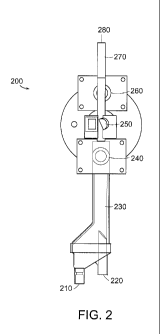
FIG. 2 is a side view of a chamber for venting gas having two level detectors
and a clamp.
FIG. 3 is a side view of a hemodialysis cassette for venting gas having two
level detectors and a clamp.
FIG. 4 is flowchart of a method for venting gas in a system having two level
detectors and a clamp.
The foregoing will be apparent from the following more particular
description of example embodiments of the invention, as illustrated in the
accompanying drawings in which like reference characters refer to the same
parts
throughout the different views. The drawings are not necessarily to scale,
emphasis
instead being placed upon illustrating embodiments of the present invention.
DETAILED DESCRIPTION OF THE INVENTION
A description of example embodiments of the invention follows.
Extracorporeal Circuit
CA 02831104 2013-09-23
WO 2012/135459
PCT/US2012/031153
- 4 -
Figure 1 illustrates a typical extracorporeal hemodialysis circuit 100, which
includes tubing through which the blood flows and components for filtering and
performing dialysis on the blood. Blood flows from a patient 105 through
arterial
tubing 110. After exiting the patient, blood drips into a drip chamber 115
where a
connecting tube 116 from the drip chamber 115 attaches to an arterial pressure
sensor assembly 120 that determines the pressure of the blood on the arterial
side of
the circuit 100.
A pump 160, such as a peristaltic pump, forces the blood to continue along
the path through the circuit 100. After exiting the drip chamber 115, the
blood then
flows through tubing 117 to a dialyzer 170, which separates waste products
from the
blood. After passing through the dialyzer 170, the blood flows through venous
tubing 180 towards a gas venting chamber 230 in which gas (e.g., air) in the
blood
can escape before the blood continues to the patient 105. After leaving the
chamber
230, the blood travels through a venous line 190 and back to the patient 105.
The
gas collection apparatus and cassette subsequently described herein can be
used with
an extracorporeal hemodialysis circuit and device, as illustrated in Figure 1.
Gas Collection Apparatus and Cassette
Figure 2 illustrates an exemplary embodiment of a gas venting apparatus 200
having a chamber, two level detectors, and a clamp. The gas venting apparatus
200
has a liquid inlet 210 and a liquid outlet 220. In Figure 2, the liquid inlet
210 is
positioned below the liquid outlet 220, but the liquid inlet 210 can also be
positioned
above the liquid outlet 220 or at approximately the same height as the liquid
outlet
220. A liquid, such as blood, enters through the liquid inlet 210 and leaves
through
the liquid outlet 220. The liquid can fill the volume of the gas collection
chamber
230.
The lower level detector 240 and the upper level detector 260 can detect the
presence of a gas or a liquid. The clamp 250 can open or close based on
signals
from the lower level detector 240 and the upper level detector 260. During
operation, the gas collection chamber initially fills with a liquid, such as
blood. The
liquid can contain gas bubbles. Over time, the gas bubbles rise to the surface
and
CA 02831104 2013-09-23
WO 2012/135459
PCT/US2012/031153
- 5 -
begin to fill the gas collection chamber with the gas, thereby creating an
interface
between the gas and the liquid. As gas bubbles continue to rise to the
surface, the
interface between the gas and the liquid moves vertically down the gas
collection
chamber.
When the lower level detector 240 detects the presence of a liquid, the clamp
250 remains closed. When the gas-liquid interface crosses the location where
the
lower level detector is positioned, the level detector can send a signal
indicative of
the presence of a gas. The signal can be sent from the lower level detector to
a
control apparatus (not shown) that receives the signal. Upon receiving the
signal,
the control apparatus can send a signal to the clamp instructing the clamp to
open.
Once the clamp opens, the gas in the gas collection chamber 230 can travel
through the gas venting tube 270. The gas venting tube 270 has a gas outlet
280. In
some embodiments, the outlet can vent gas to the atmosphere. When the clamp is
open, the gas collection chamber 230 is in fluid communication with the gas
vent
tube 270, which in turn is in fluid communication with the atmosphere.
Ordinarily, the pressure in the gas collection chamber is greater than
atmospheric pressure. Thus when the clamp 250 is open, the gas-liquid
interface
moves vertically up the gas collection chamber, which expunges accumulated gas
to
the atmosphere.
Similar to the lower level detector, the upper level detector 260 detects the
presence of a gas or a liquid. When the clamp 250 is open, the gas-liquid
interface
can move vertically up the chamber and can cross the location where the upper
level
detector is positioned. When the upper level detector 260 detects the presence
of a
gas, the clamp can remain open, thus permitting further venting of gas to the
atmosphere. When the upper level detector 260 detects the presence of a
liquid, the
clamp 250 can close, thus preventing the liquid from reaching the gas outlet
280. In
some embodiments, the upper level detector can send a signal indicative of the
presence of a gas or a liquid to the control apparatus (not shown). The
control
apparatus can then send a signal to the clamp that opens or closes the clamp.
Figure 3 illustrates a gas venting cassette 300 having a chamber, two level
detectors, and a clamp. Figure 3 is similar to figure 2, except that figure 3
is a
CA 02831104 2013-09-23
WO 2012/135459
PCT/US2012/031153
- 6 -
cassette 300 including a liquid inlet 310, a liquid outlet 320, a gas
collection
chamber 330, a lower level detector 340, a clamp 350, an upper level detector
360, a
gas vent tube 370, and a gas outlet 380. The embodiment of Figure 3 operates
similarly to the embodiment of Figure 2. The primary difference between the
embodiments of figure 2 and figure 3 is in the shape of the gas collection
chamber.
The term "clamp" is used in its broadest sense, meaning that it is an element
that is capable of opening and closing the gas vent tube. In one embodiment,
the
clamps (250 and 350) can be pinch clamps that, in a closed position, exert
pressure
on a tube to prevent the passage of gas or liquid. In another embodiment, the
clamps
(250 and 350) can be balloon clamps. A wide variety of suitable devices that
can
open and close the gas vent tube in response to a signal can be used.
In one embodiment, the level detectors (240, 260, 340, and 360) can detect
the density of a substance. Liquids generally have a higher density than
gasses.
Thus, the level detector can send a signal indicative of the density of a
substance,
wherein the density is indicative of the presence of a gas or a liquid. In
some
embodiments, the liquid can be blood. In some embodiments, the gas can be air.
The gas bubbles can be dissolved in the liquid, or the gas bubbles can be too
large to be considered dissolved in the liquid. In some cases, the gas bubbles
can be
observable with the naked eye. In other cases, the gas bubbles can on the
order of
magnitude of a millimeter or less.
The gas collection chamber (230 and 330) and the gas vent tube (270 and
370) are not necessarily separate pieces. Rather, the two can be an integrated
component. In other words, the gas collection chamber and the gas vent tube
can be
a single, integral unit. While figues 2 and 3 illustrate the lower level
detector (240
and 340) positioned at the gas collection chamber (230 and 330) and the upper
level
detector (260 and 360) positioned at the gas vent chamber (270 and 370), the
lower
and upper level detectors (240, 260, 340, and 360) can be positioned at either
the gas
collection chamber (230 and 330) or at the gas vent tube (270 and 370).
Typically, the gas outlet (280 and 380) is capped with a hydrophobic
membrane, such as a polytetrafluoroethylene (PTFE) or polyethylene (PE)
membrane, though other suitable hydrophobic membranes can also be used.
CA 02831104 2013-09-23
WO 2012/135459
PCT/US2012/031153
- 7 -
The chamber embodiment of figure 2 and the cassette embodiment of figure
3 can be made of a wide variety of materials suitable for medical
applications, and
can be formed into the appropriate shape any processes suitable for medial
applications.
Typically, the liquid inlet (210 and 310) and the liquid outlet (220 and 320)
connect to tubing. As shown in Figure 1, the liquid inlet (210 and 310)
connects to
tubing 180, and the liquid outlet (220 and 320) connect to tubing 190. The
tubing
can be of a wide variety of materials suitable for medical application.
Operation of the Gas Collection Apparatus and Cassette
Figure 4 is a flowchart illustrating steps in a method for venting gas in a
system having a gas collection chamber, two level detectors, and a clamp. In
one
embodiment, the clamp is initially in a closed position. Optionally, the clamp
can be
closed if it is open (step 405). Liquid flows into the gas collection chamber
(step
410). The liquid enters the gas collection chamber via a liquid inlet, such as
liquid
inlet 210 or 310. The lower level detector detects the presence of a liquid or
gas
(step 420). If liquid is present at the lower level detector (i.e., if gas is
not present),
the clamp remains closed and liquid continues to flow into the gas collection
chamber (step 410). If liquid is not present at the lower level detector
(i.e., if gas is
present at the lower level detector), the clamp opens (step 430).
While the clamp is open, gas in the gas collection chamber is in fluid
communication with the atmosphere via a gas venting tube, and gas can vent to
the
atmosphere. As gas vents to the atmosphere, the gas-liquid interface rises.
The
upper level detector detects the presence of a liquid or a gas (step 440). If
liquid is
not present at the upper level detector (i.e., if gas is present), the clamp
remains open
(step 430), and the upper level detector continues to detect the presence of
liquid or
gas (step 440). If liquid is present at the upper level detector (i.e., if gas
is not
present), then the clamp closes (step 460). Liquid continues to flow into the
gas
collection chamber (step 410) and the cycle repeats.
While Figures 4 describes detecting liquid at the upper level detector at step
440, the upper level detector can detect the presence of liquid or gas at the
outset.
CA 02831104 2013-09-23
WO 2012/135459
PCT/US2012/031153
- 8 -
However, the system and method do not need to consider the presence or absence
of
gas or liquid at the upper level detector until the clamp has opened.
While steps 420 and 440 described detecting whether liquid is present at the
level detectors, it is equivalent to detect whether gas is present. In such
case, the
relative placement of the "Yes" and "No" answers to the inquiry are reversed.
In
other words, if gas is present at the lower level detector (step 420), then
the clamp
opens (step 430), and if gas is not present, then the clamp remains closed
(step 410).
Similarly, if gas is present at the upper level detector (step 440), then the
clamp
remains open (step 430), and if gas is not present, then the clamp closes
(step 460).
While this invention has been particularly shown and described with
references to example embodiments thereof, it will be understood by those
skilled in
the art that various changes in form and details may be made therein without
departing from the scope of the invention encompassed by the appended claims.