Note: Descriptions are shown in the official language in which they were submitted.
CONTINUOUS FIBER REINFORCED THERMOPLASTIC RODS
AND PULTRUSION METHOD FOR ITS MANUFACTURE
[0001] This application relates to U.S. Provisional Patent Application
Serial No.
61/474,481, filed April 12, 2011, titled: "CONTINUOUS FIBER REINFORCED
THERMOPLASTIC RODS".
Background of the Invention
[0002] Fiber-reinforced composite rods have been employed in a wide
variety of
applications as lightweight structural reinforcements. For example, power
umbilicals are
often used in the transmission of fluids and/or electric signals between the
sea surface
and equipment located on the sea bed. Such umbilicals generally include one or
more
pipes and electric conductors/wires collected in a bundle, a filler material
arranged at
least partly around and between the pipes and conductors/wires, and a
protective
sheath enclosing the pipes, conductors/wires, and filler material. To help
strengthen
such umbilicals, attempts have been made to use pultruded carbon fiber rods as
separate load carrying elements. A significant problem with such rods however,
it is
that they rely upon thermoset resins (e.g., vinyl esters) to help achieve the
desired
strength properties. Thermoset resins are difficult to use during
manufacturing and do
not possess good bonding characteristics for forming layers with other
materials.
Attempts have been made to form rods from thermoplastic polymers in other
types of
applications. U.S. Patent Publication No. 2005/0186410 to Bryant, et al., for
instance,
describes attempts that were made to embed carbon fibers into a thermoplastic
resin to
form a composite core of an electrical transmission cable. Unfortunately,
Bryant, et al.
notes that these cores exhibited flaws and dry spots due to inadequate wetting
of the
fibers, which resulted in poor durability and strength. Another problem with
such cores
is that the thermoplastic resins could not operate at a high temperature.
[0003] As such, a need currently exists for a fiber-reinforced rod that is
formed
from a thermoplastic material, and yet is still capable of achieving the
desired strength,
durability, and temperature performance demanded by a particular application.
Summary of the Invention
[0004] In accordance with one embodiment of the present invention, a
composite rod is disclosed that extends in a longitudinal direction. The rod
has a core
1
CA 2831358 2018-08-24
that contains a plurality of thermoplastic impregnated rovings comprising
continuous
fibers oriented in the longitudinal direction and a thermoplastic matrix that
embeds the
fibers. The fibers have a ratio of ultimate tensile strength to mass per unit
length of
greater than 1,000 Megapascals per gram per meter. The continuous fibers
constitute
from 25 wt.% to 80 wt.% of the core and the thermoplastic matrix constitutes
from 20
wt.% to 75 wt.% of the core. The rod has a minimum flexural modulus of 10
Gigapascals and the bend radius is less than 40 times the outer diameter of
the rod.
[0005] In accordance with another embodiment of the present invention, a
method for forming a composite rod extending in a longitudinal direction is
disclosed.
The method comprises impregnating a plurality of rovings with a thermoplastic
matrix
and consolidating the rovings to form a ribbon, wherein the rovings comprise
continuous
fibers oriented in the longitudinal direction and having a ratio of ultimate
tensile strength
to mass per unit length of greater than 1,000 Megapascals per gram per meter.
The
continuous fibers constitute from 25 wt.% to 80 wt.% of the ribbon and the
thermoplastic
matrix constitutes from 20 wt.% to 75 wt.% of the ribbon. The ribbon has a
void fraction
of about 3% or less. The ribbon is heated to a temperature at or above the
softening
temperature of the thermoplastic matrix and pulled through at least one
forming die to
compress and shape the ribbon into a preform. The preform is cooled to form
the rod,
wherein the rod has a minimum flexural modulus of 10 Gigapascals and wherein
the
bend radius is less than 40 times the outer diameter of the rod.
[0006] Other features and aspects of the present invention are set forth
in greater
detail below.
Brief Description of the Drawings
[0007] A full and enabling disclosure of the present invention, including
the best
mode thereof to one skilled in the art, is set forth more particularly in the
remainder of
the specification, including reference to the accompanying figures, in which:
[0008] Fig. 1 is a perspective view of one embodiment of a consolidated
ribbon
for use in the present invention;
[0009] Fig. 2 is a cross-sectional view of another embodiment of a
consolidated
ribbon for use in the present invention;
2
CA 2831358 2018-08-24
CA 02831358 2013-09-24
WO 2012/142107 PCT/US2012/033048
[0010] Fig. 3 is a schematic illustration of one embodiment of an
impregnation system for use in the present invention;
[0011] Fig. 4 is a cross-sectional view of the impregnation die shown in
Fig.
3;
[0012] Fig. 5 is an exploded view of one embodiment of a manifold
assembly and gate passage for an impregnation die that may be employed in the
present invention;
[0013] Fig. 6 is a perspective view of one embodiment of a plate at least
partially defining an impregnation zone that may be employed in the present
invention;
[0014] Fig. 7 is a schematic illustration of one embodiment of a
pultrusion
system that may be employed in the present invention;
[0015] Fig. 8 is a perspective view of one embodiment of a continuous
fiber
reinforced thermoplastic rod of the present invention;
[0016] Fig. 9 is a top cross-sectional view of one embodiment of various
calibration dies that may be employed in accordance with the present
invention;
[0017] Fig. 10 is a side cross-sectional view of one embodiment of a
calibration die that may be employed in accordance with the present invention;
[0018] Fig. Ills a front view of a portion of one embodiment of a
calibration
die that may be employed in accordance with the present invention; and
[0019] Fig. 12 is a front view of one embodiment of forming rollers that
may
be employed in accordance with the present invention.
[0020] Repeat use of reference characters in the present specification
and
drawings is intended to represent the same or analogous features or elements
of
the present invention.
Detailed Description of Representative Embodiments
[0021] It is to be understood by one of ordinary skill in the art that
the
present discussion is a description of exemplary embodiments only, and is not
intended as limiting the broader aspects of the present invention.
[0022] Generally speaking, the present invention is directed to a
composite
rod for use in various applications, such as electrical cables (e.g., high
voltage
transmission cables), power umbilicals, tethers, ropes, and a wide variety of
other
structural members. The rod includes a core that is formed from a plurality of
3
CA 02831358 2013-09-24
WO 2012/142107 PCT/US2012/033048
unidirectionally aligned fiber ravings embedded within a thermoplastic polymer
matrix. The present inventors have discovered that the degree to which the
rovings are impregnated with the thermoplastic polymer matrix can be
significantly
improved through selective control over the impregnation process, and also
through control over the degree of compression imparted to the rovings during
formation and shaping of the rod, as well as the calibration of the final rod
geometry. Such a well impregnated rod has a very small void fraction, which
leads
to excellent strength properties. Notably, the desired strength properties may
be
achieved without the need for different fiber types in the rod.
[0023] As used herein, the term "roving" generally refers to a bundle or
tow
of individual fibers. The fibers contained within the roving can be twisted or
can be
straight. Although different fibers can be used in individual or different
rovings, it is
generally desired that each of the rovings contain a single fiber type to
minimize
any adverse impact of using material with a different thermal coefficient of
expansion. The continuous fibers employed in the ravings possess a high degree
of tensile strength relative to their mass. For example, the ultimate tensile
strength
of the fibers is typically from about 1,000 to about 15,000 Megapascals
("MPa"), in
some embodiments from about 2,000 MPa to about 10,000 MPa, and in some
embodiments, from about 3,000 MPa to about 6,000 MPa. Such tensile strengths
may be achieved even though the fibers are of a relatively light weight, such
as a
mass per unit length of from about 0.1 to about 2 grams per meter, in some
embodiments from about 0.4 to about 1.5 grams per meter. The ratio of tensile
strength to mass per unit length may thus be about 1,000 Megapascals per gram
per meter ("MPa/g/m") or greater, in some embodiments about 4,000 MPa/g/m or
greater, and in some embodiments, from about 5,500 to about 20,000 MPa/g/m.
Such high strength fibers may, for instance, be metal fibers, glass fibers
(e.g., E-
glass, A-glass, C-glass, 0-glass, AR-glass, R-glass, Sl-glass, S2-glass,
etc.),
carbon fibers (e.g., amorphous carbon, graphitic carbon, or metal-coated
carbon,
etc.), boron fibers, ceramic fibers (e.g., alumina or silica), aramid fibers
(e.g.,
Kevlar0 marketed by E. I. duPont de Nemours, Wilmington, Del.), synthetic
organic fibers (e.g., polyamide, polyethylene, paraphenylene, terephthalamide,
polyethylene terephthalate and polyphenylene sulfide), and various other
natural or
synthetic inorganic or organic fibrous materials known for reinforcing
thermoplastic
4
CA 02831358 2013-09-24
WO 2012/142107 PCT/US2012/033048
compositions. Carbon fibers are particularly suitable for use as the
continuous
fibers, which typically have a tensile strength to mass ratio in the range of
from
about 5,000 to about 7,000 MPa/g/m. The continuous fibers often have a nominal
diameter of about 4 to about 35 micrometers, and in some embodiments, from
about 5 to about 35 micrometers. The number of fibers contained in each roving
can be constant or vary from roving to roving. Typically, a roving contains
from
about 1,000 fibers to about 100,000 individual fibers, and in some
embodiments,
from about 5,000 to about 50,000 fibers.
[0024] Any of a variety of thermoplastic polymers may be employed to form
the thermoplastic matrix in which the continuous fibers are embedded. Suitable
thermoplastic polymers for use in the present invention may include, for
instance,
polyolefins (e.g., polypropylene, propylene-ethylene copolymers, etc.),
polyesters
(e.g., polybutylene terephalate ("PBT")), polycarbonates, polyamides (e.g.,
Nylon TM), polyether ketones (e.g., polyetherether ketone ("PEEK")),
polyetherimides, polyarylene ketones (e.g., polyphenylene diketone ("PPDK")),
liquid crystal polymers, polyarylene sulfides (e.g., polyphenylene sulfide
("PPS"),
poly(biphenylene sulfide ketone), poly(phenylene sulfide diketone),
poly(biphenylene sulfide), etc.), fluoropolymers (e.g.,
polytetrafluoroethylene-
perfluoromethylvinylether polymer, perfluoro-alkoxyalkane polymer,
petrafluoroethylene polymer, ethylene-tetrafluoroethylene polymer, etc.),
polyacetals, polyurethanes, polycarbonates, styrenic polymers (e.g.,
acrylonitrile
butadiene styrene ("ABS")), and so forth.
[0025] The properties of the thermoplastic matrix are generally selected
to
achieve the desired combination of processability and performance of the rod
during use. For example, the melt viscosity of the thermoplastic matrix is
generally
low enough so that the polymer can adequately impregnate the fibers and become
shaped into the rod configuration. In this regard, the melt viscosity
typically ranges
from about 25 to about 2,000 Pascal-seconds ("Pa-s"), in some embodiments from
50 about 500 Pa-s, and in some embodiments, from about 60 to about 200 Pa-s,
determined at the operating conditions used for th.e thermoplastic polymer
(e.g.,
about 360 C). Likewise, when the rod is intended for use at high temperatures,
a
thermoplastic polymer is employed that has a relatively high melting
temperature.
For example, the melting temperature of such high temperature polymers may
range from about 200 C to about 500 C, in some embodiments from about 225 C to
about 400 C, and in some embodiments, from about 250 C to about 350 C.
[0026] Polyarylene sulfides are particularly suitable for use in the
present
invention as a high temperature matrix with the desired melt viscosity.
Polyphenylene
sulfide, for example, is a semi-crystalline resin that generally includes
repeating
monomeric units represented by the following general formula:
[0027] These monomeric units typically constitute at least 80 mole%, and
in
some embodiments, at least 90 mole%, of the recurring units, in the polymer.
It should
be understood, however, the polyphenylene sulfide may contain additional
recurring
units, such as described in U.S. Patent No. 5,075,381 to Gotoh, et al. When
employed,
such additional recurring units typically constitute no more than about 20
mole% of the
polymer. Commercially available high melt viscosity polyphenylene sulfides may
include those available from Ticona LLC (Florence, Kentucky) under the trade
designation FORTRON . Such polymers may have a melting temperature of about
285 C (determined according to ISO 11357-1,2,3) and a melt viscosity of from
about
260 to about 320 Pascal-seconds at 310 C.
[0028] According to the present invention, an extrusion device is
generally employed
to impregnate the rovings with the thermoplastic matrix. Among other things,
the extrusion
device facilitates the ability of the thermoplastic polymer to be applied to
the entire surface
of the fibers. The impregnated rovings also have a very low void fraction,
which helps
enhance its strength. For instance, the void fraction may be about 6% or less,
in some
embodiments about 4% or less, in some embodiments about 3% or less, in some
embodiments about 2% or less, in some embodiments about 1% or less, and in
some
embodiments, about 0.5% or less. The void fraction may be measured using
techniques
well known to those skilled in the art. For example, the void fraction may be
measured
using a "resin burn off' test in which samples are placed in an oven (e.g., at
600 C for 3
hours) to burn out the resin. The mass of the remaining fibers may then be
measured to
calculate the weight and volume fractions. Such "burn off' testing may be
performed in
6
CA 2831358 2018-08-24
CA 02831358 2013-09-24
WO 2012/142107 PCT/US2012/033048
accordance with ASTM ID 2584-08 to determine the weights of the fibers and the
thermoplastic matrix, which may then be used to calculate the "void fraction"
based
on the following equations:
Vf = 100 *(pp )/p
where,
Vf is the void fraction as a percentage;
pc is the density of the composite as measured using known techniques,
such as with a liquid or gas pycnometer (e.g., helium pycnometer);
pt is the theoretical density of the composite as is determined by the
following equation:
Pt = 1/ [MVP+ Wm 4014
Pm is the density of the thermoplastic matrix (e.g., at the appropriate
crystallinity);
pf is the density of the fibers;
Wf is the weight fraction of the fibers; and
Wm is the weight fraction of the thermoplastic matrix.
[0029] Alternatively, the void fraction may be determined by chemically
dissolving the resin in accordance with ASTM D 3171-09. The "burn off" and
"dissolution" methods are particularly suitable for glass fibers, which are
generally
resistant to melting and chemical dissolution. In other cases, however, the
void
fraction may be indirectly calculated based on the densities of the
thermoplastic
polymer, fibers, and ribbon (or tape) in accordance with ASTM D 2734-09
(Method
A), where the densities may be determined ASTM D792-08 Method A. Of course,
the void fraction can also be estimated using conventional microscopy
equipment,
or through the use of computed tomography (CT) scar equipment, such as a
Metrotom 1500 (2k x 2k) high resolution detector..
[0030] Referring to Fig. 3, one embodiment of such an extrusion device is
shown. More particularly, the apparatus includes an extruder 120 containing a
screw shaft 124 mounted inside a barrel 122. A heater 130 (e.g., electrical
resistance heater) is mounted outside the barrel 122. During use, a
thermoplastic
polymer feedstock 127 is supplied to the extruder 120 through a hopper 126.
The
thermoplastic feedstock 127 is conveyed inside the barrel 122 by the screw
shaft
7
CA 02831358 2013-09-24
WO 2012/142107 PCT/US2012/033048
124 and heated by frictional forces inside the barrel 122 and by the heater
130.
Upon being heated, the feedstock 127 exits the barrel 122 through a barrel
flange
128 and enters a die flange 132 of an impregnation die 150.
[0031] A continuous fiber roving 142 or a plurality of continuous fiber
rovings
142 are supplied from a reel or reels 144 to die 150. The rovings 142 are
generally kept apart a certain distance before impregnation, such as at least
about
4 millimeters, and in some embodiments, at least about 5 millimeters. The
feedstock 127 may further be heated inside the die by heaters 133 mounted in
or
around the die 150. The die is generally operated at temperatures that are
sufficient to cause melting and impregnation of the thermoplastic polymer.
Typically, the operation temperatures of the die is higher than the melt
temperature
of the thermoplastic polymer, such as at temperatures from about 200 C to
about
450 C. When processed in this manner, the continuous fiber rovings 142 become
embedded in the polymer matrix, which may be a resin 214 (Fig. 4) processed
from the feedstock 127. The mixture is then extruded from the impregnation die
150 to create an extrudate 152.
[0032] A pressure sensor 137 (Fig. 4) senses the pressure near the
impregnation die 150 to allow control to be exerted over the rate of extrusion
by
controlling the rotational speed of the screw shaft 124, or the federate of
the
feeder. That is, the pressure sensor 137 is positioned near the impregnation
die
150 so that the extruder 120 can be operated to deliver a correct amount of
resin
214 for interaction with the fiber rovings 142. After leaving the impregnation
die
150, the extrudate 152, or impregnated fiber ravings 142, may enter an
optional
pre-shaping, or guiding section (not shown) before entering a nip formed
between
two adjacent rollers 190. Although optional, the rollers 190 can help to
consolidate
the extrudate 152 into the form of a ribbon (or tape), as well as enhance
fiber
impregnation and squeeze out any excess voids. In addition to the rollers 190,
other shaping devices may also be employed, such as a die system. The
resulting
consolidated ribbon 156 is pulled by tracks 162 and 164 mounted on rollers.
The
tracks 162 and 164 also pull the extrudate 152 from the impregnation die 150
and
through the rollers 190. If desired, the consolidated ribbon 156 may be wound
up
at a section 171. Generally speaking, the ribbons are relatively thin and
typically
have a thickness of from about 0.05 to about 1 millimeter, in some embodiments
8
CA 02831358 2013-09-24
WO 2012/142107 PCT/US2012/033048
from about 0.1 to about 0.8 millimeters, and in some embodiments, from about
0.2
to about 0.4 millimeters.
[0033] Within the impregnation die, it is generally desired that the
ravings
142 are traversed through an impregnation zone 250 to impregnate the ravings
with the polymer resin 214. In the impregnation zone 250, the polymer resin
may
be forced generally transversely through the ravings by shear and pressure
created in the impregnation zone 250, which significantly enhances the degree
of
impregnation. This is particularly useful when forming a composite from
ribbons of
a high fiber content, such as about 35% weight fraction ("Wf") or more, and in
some embodiments, from about 40% Wf or more. Typically, the die 150 will
include a plurality of contact surfaces 252, such as for example at least 2,
at least
3, from 4 to 7, from 2 to 20, from 2 to 30, from 2 to 40, from 2 to 50, or
more
contact surfaces 252, to create a sufficient degree of penetration and
pressure on
the rovings 142. Although their particular form may vary, the contact surfaces
252
typically possess a curvilinear surface, such as a curved lobe, rod, etc. The
contact surfaces 252 are also typically made of a metal material.
[0034] Fig. 4 shows a cross-sectional view of an impregnation die 150. As
shown, the impregnation die 150 includes a manifold assembly 220, a gate
passage 270, and an impregnation zone 250. The manifold assembly 220 is
provided for flowing the polymer resin 214 therethrough. For example, the
manifold assembly 220 may include a channel 222 or a plurality of channels
222.
The resin 214 provided to the impregnation die 150 may flow through the
channels
222.
[0035] As shown in Fig. 5, some portions of the channels 222 may be
curvilinear, and in exemplary embodiments, the channels 222 have a symmetrical
orientation along a central axis 224. Further, in some embodiments, the
channels
may be a plurality of branched runners 222, which may include first branched
runner group 232, second group 234, third group 236, and, if desired, more
branched runner groups. Each group may include 2, 3, 4 or more runners 222
branching off from runners 222 in the preceding group, or from an initial
channel
222.
[0036] The branched runners 222 and the symmetrical orientation thereof
generally evenly distribute the resin 214, such that the flow of resin 214
exiting the
9
CA 02831358 2013-09-24
WO 2012/142107 PCT/US2012/033048
manifold assembly 220 and coating the ravings 142 is substantially uniformly
distributed on the ravings 142. This desirably allows for generally uniform
impregnation of the ravings 142.
[0037] Further, the manifold assembly 220 may in some embodiments
define an outlet region 242, which generally encompasses at least a downstream
portion of the channels or runners 222 from which the resin 214 exits. In some
embodiments, at least a portion of the channels or runners 222 disposed in the
outlet region 242 have an increasing area in a flow direction 244 of the resin
214.
The increasing area allows for diffusion and further distribution of the resin
214 as
the resin 214 flows through the manifold assembly 220, which further allows
for
substantially uniform distribution of the resin 214 on the rovings 142.
[0038] As further illustrated in Figs. 4 and 5, after flowing through the
manifold assembly 220, the resin 214 may flow through gate passage 270. Gate
passage 270 is positioned between the manifold assembly 220 and the
impregnation zone 250, and is provided for flowing the resin 214 from the
manifold
assembly 220 such that the resin 214 coats the ravings 142. Thus, resin 214
exiting the manifold assembly 220, such as through outlet region 242, may
enter
gate passage 270 and flow therethrough, as shown.
[0039] Upon exiting the manifold assembly 220 and the gate passage 270 of
the die 150 as shown in Fig 4, the resin 214 contacts the ravings 142 being
traversed through the die 150. As discussed above, the resin 214 may
substantially uniformly coat the rovings 142, due to distribution of the resin
214 in
the manifold assembly 220 and the gate passage 270. Further, in some
embodiments, the resin 214 may impinge on an upper surface of each of the
ravings 142, or on a lower surface of each of the ravings 142, or on both an
upper
and lower surface of each of the ravings 142. Initial impingement on the
ravings
142 provides for further impregnation of the ravings 142 with the resin 214.
[0040] As shown in Fig. 4, the coated ravings 142 are traversed in run
direction 282 through impregnation zone 250, which is configured to impregnate
the ravings 142 with the resin 214. For example, as shown in Figs. 4 and 6,
the _
rovings 142 are traversed over contact surfaces 252 in the impregnation zone.
Impingement of the ravings 142 on the contact surface 252 creates shear and
CA 02831358 2013-09-24
WO 2012/142107 PCT/US2012/033048
pressure sufficient to impregnate the ravings 142 with the resin 214 coating
the
rovings 142.
[0041] In some embodiments, as shown in Fig. 4, the impregnation zone
250 is defined between two spaced apart opposing plates 256 and 258. First
plate
256 defines a first inner surface 257, while second plate 258 defines a second
inner surface 259. The contact surfaces 252 may be defined on or extend from
both the first and second inner surfaces 257 and 259, or only one of the first
and
second inner surfaces 257 and 259. Fig. 6 illustrates the second plate 258 and
the
various contact surfaces thereon that form at least a portion of the
impregnation
zone 250 according to these embodiments. In exemplary embodiments, as shown
in Fig. 4, the contact surfaces 252 may be defined alternately on the first
and
second surfaces 257 and 259 such that the rovings alternately impinge on
contact
surfaces 252 on the first and second surfaces 257 and 259. Thus, the ravings
142
may pass contact surfaces 252 in a waveform, tortuous or sinusoidual-type
pathway, which enhances shear.
[0042] Angle 254 at which the rovings 142 traverse the contact surfaces
252
may be generally high enough to enhance shear, but not so high to cause
excessive forces that will break the fibers. Thus, for example, the angle 254
may
be in the range between approximately 10 and approximately 30 , and in some
embodiments, between approximately 50 and approximately 25 .
[0043] In alternative embodiments, the impregnation zone 250 may include
a plurality of pins (not shown), each pin having a contact surface 252. The
pins
may be static, freely rotational, or rotationally driven. In further
alternative
embodiments, the contact surfaces 252 and impregnation zone 250 may comprise
any suitable shapes and/or structures for impregnating the rovings 142 with
the
resin 214 as desired or required.
[0044] To further facilitate impregnation of the rovings 142, they may
also be
kept under tension while present within the impregnation die. The tension may,
for
example, range from about 5 to about 300 Newtons, in some embodiments from
about 50 to about 250 Newtons, and in some embodiments, from about 100 to
= about 200 Newtons per roving 142 or tow of fibers.
[0045] As shown in Fig. 4, in some embodiments, a land zone 280 may be
positioned downstream of the impregnation zone 250 in run direction 282 of the
11
rovings 142. The rovings 142 may traverse through the land zone 280 before
exiting
the die 150. As further shown in Fig. 4, in some embodiments, a faceplate 290
may
adjoin the impregnation zone 250. Faceplate 290 is generally configured to
meter
excess resin 214 from the rovings 142. Thus, apertures in the faceplate 290,
through
which the rovings 142 traverse, may be sized such that when the rovings 142
are
traversed therethrough, the size of the apertures causes excess resin 214 to
be
removed from the rovings 142.
[0046] The impregnation die shown and described above is but one of
various
possible configurations that may be employed in the present invention. In
alternative
embodiments, for example, the rovings may be introduced into a crosshead die
that is
positioned at an angle relative to the direction of flow of the polymer melt.
As the
rovings move through the crosshead die and reach the point where the polymer
exits
from an extruder barrel, the polymer is forced into contact with the rovings.
Examples of
such a crosshead die extruder are described, for instance, in U.S. Patent Nos.
3,993,726 to Moyer; 4,588,538 to Chung, et al.; 5,277,566 to Augustin, et al.;
and
5,658,513 to Amaike,et al. It should also be understood that any other
extruder design
may also be employed, such as a twin screw extruder. Still further, other
components
may also be optionally employed to assist in the impregnation of the fibers.
For
example, a "gas jet" assembly may be employed in certain embodiments to help
uniformly spread a roving of individual fibers, which may each contain up to
as many as
24,000 fibers, across the entire width of the merged tow. This helps achieve
uniform
distribution of strength properties. Such an assembly may include a supply of
compressed air or another gas that impinges in a generally perpendicular
fashion on the
moving rovings that pass across the exit ports. The spread rovings may then be
introduced into a die for impregnation, such as described above.
[0047] Regardless of the technique employed, the continuous fibers are
oriented
in the longitudinal direction (the machine direction "A" of the system of Fig.
3) to
12
CA 2831358 2018-08-24
enhance tensile strength. Besides fiber orientation, other aspects of the
pultrusion
process are also controlled to achieve the desired strength. For example, a
relatively
high percentage of continuous fibers are employed in the consolidated ribbon
to provide
enhanced strength properties. For instance,
12a
CA 2831358 2018-08-24
CA 02831358 2013-09-24
WO 2012/142107 PCT/US2012/033048
continuous fibers typically constitute from about 25 wt.% to about 80 wt.%, in
some embodiments from about 30 wt.% to about 75 wt.%, and in some
embodiments, from about 35 wt.% to about 60 wt.% of the ribbon. Likewise,
thermoplastic polymer(s) typically constitute from about 20 wt.% to about 75
wt.%,
in some embodiments from about 25 wt.% to about 70 wt.%, and in some
embodiments, from about 40 wt.% to about 65 wt.% of the ribbon. The percentage
of the fibers and thermoplastic matrix in the final rod may also be within the
ranges
noted above.
[0048] As noted above, the rovings may be consolidated into the form of
one or more ribbons before being shaped into the desired rod configuration.
When
such a ribbon is subsequently compressed, the rovings can become distributed
in
a generally uniform manner about a longitudinal center of the rod. Such a
uniform
distribution enhances the consistency of the strength properties (e.g.,
flexural
modulus, ultimate tensile strength, etc.) over the entire length of the rod.
When
employed, the number of consolidated ribbons used to form the rod will vary
based
on the desired thickness and/or cross-sectional area and strength of the rod,
as
well as the nature of the ribbons themselves. In most cases, however, the
number
of ribbons is from 1 to 20, and in some embodiments, from 2 to 10. The number
of
rovings employed in each ribbon may likewise vary. Typically, however, a
ribbon
will contain from 2 to 10 ravings, and in some embodiments, from 3 to 5
rovings.
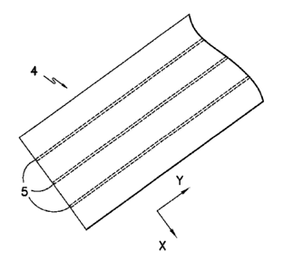
To help achieve the symmetric distribution of the rovings in the final rod, it
is
generally desired that they are spaced apart approximately the same distance
from
each other within the ribbon. Referring to Fig. 1, for example, one embodiment
of
a consolidated ribbon 4 is shown that contains three (3) ravings 5 spaced
equidistant from each other in the ¨x direction. In other embodiments,
however, it
may be desired that the rovings are combined, such that the fibers of the
ravings
are generally evenly distributed throughout the ribbon 4. In these
embodiments,
the rovings may be generally indistinguishable from each other. Referring to
Fig.
2, for example, one embodiment of a consolidated ribbon 4 is shown that
contains
rovings that are combined such that the fibers are generally evenly
distributed.
[0049] The specific manner in which the rovings are shaped is also
carefully
controlled to ensure that rod can be formed with an adequate degree of
compression and strength properties. Referring to Fig. 7, for example, one
13
CA 02831358 2013-09-24
WO 2012/142107 PCT/US2012/033048
particular embodiment of a system and method for forming a rod are shown. In
this embodiment, two ribbons 12 are initially provided in a wound package on a
creel 20. The creel 20 may be an unreeling creei that includes a frame
provided
with horizontal rotating spindles 22, each supporting a package. A pay-out
creel
may also be employed, particularly if desired to induce a twist into the
fibers, such
as when using raw fibers in a one-step configuration. It should also be
understood
that the ribbons may also be formed in-Line with the formation of the rod. In
one
embodiment, for example, the extrudate 152 exiting the impregnation die 150
from
Fig. 3 may be directly supplied to the system used to form a rod. A tension-
regulating device 40 may also be employed to help control the degree of
tension in
the ribbons 12. The device 40 may include inlet plate 30 that lies in a
vertical
plane parallel to the rotating spindles 22 of the creel 20 and/or
perpendicular to the
incoming ribbons. The tension-regulating device 40 may contain cylindrical
bars
41 arranged in a staggered configuration so that the ribbon 12 passes over and
under these bars to define a wave pattern. The height of the bars can be
adjusted
to modify the amplitude of the wave pattern and control tension.
[0050] The ribbons 12 may be heated in an oven 45 before entering the
consolidation die. Heating may be conducted using any known type of oven, as
in
an infrared oven, convection oven, etc. During heating, the fibers in the
ribbon are
unidirectionally oriented to optimize the exposure to the heat and maintain
even
heat across the entire ribbon. The temperature to which the ribbons 12 are
heated
is generally high enough to soften the thermoplastic polymer to an extent that
the
ribbons can bond together. However, the temperature is not so high as to
destroy
the integrity of the material. The temperature may, for example, range from
about
100 C to about 500 C, in some embodiments from about 200 C to about 400 C,
and in some embodiments, from about 250 C to about 350 C. In one particular
embodiment, for exampie, polyphenylene sulfide ("PPS") is used as the polymer,
and the ribbons are heated to or above the melting point of PPS, which is
about
285 C.
[0051] Upon being heated, the ribbons 12 are provided to a consolidation
die 50 that compresses them together into a preform 14, as well as aligns and
forms the initial shape of the rod. As shown generally in Fig. 7, for example,
the
ribbons 12 are guided through a flow passage 51 of the die 50 in a direction
"A"
14
CA 02831358 2013-09-24
WO 2012/142107
PCT/US2012/033048
from an inlet 63 to an outlet 55. The passage 51 may have any of a variety of
shapes and/or sizes to achieve the rod configuration. For example, the channel
and rod configuration may be circular, elliptical, parabolic, etc. Within the
die 50,
the ribbons are generally maintained at a temperature at or above the melting
point
of the thermoplastic matrix used in the ribbon to ensure adequate
consolidation.
[0052] The desired
heating, compression, and shaping of the ribbons 12
may be accomplished through the use of a die 50 having one or multiple
sections.
For instance, although not shown in detail herein, the consolidation die 50
may
possess multiple sections that function together to compress and shape the
ribbons 12 into the desired configuration. For instance, a first section of
the
passage 51 may be a tapered zone that initially shapes the material as it
flows
from into the die 50. The tapered zone generally possesses a cross-sectional
area
that is larger at its inlet than at its outlet. For example, the cross-
sectional area of
the passage 51 at the inlet of the tapered zone may be about 2% or more, in
some
embodiments about 5% or more, and in some embodiments, from about 10% to
about 20% greater than the cross-sectional area at the outlet of the tapered
zone.
Regardless, the cross-sectional of the flow passage typically changes
gradually
and smoothly within the tapered zone so that a balanced flow of the composite
material through the die can be maintained. A shaping zone may also follow the
tapered zone that compresses the material and provides a generally
homogeneous flow therethrough. The shaping zone may also pre-shape the
material into an intermediate shape that is similar to that of the rod, but
typically of
a larger cross-sectional area to allow for expansion of the thermoplastic
polymer
while heated to minimize the risk of backup within the die 50. The shaping
zone
could also include one or more surface features that impart a directional
change to
the preform. The directional change forces the material to be redistributed
resulting in a more even distribution of the fiber/resin in the final shape.
This also
reduces the risk of dead spots in the die that can cause burning of the resin.
For
example, the cross-sectional area of the passage 51 at the shaping zone may be
about 2% or more, in some embodiments about 5% or more, and in some
embodiments, from about 10% to about 20% greater than the width of the preform
14. A die land may also follow the shaping zone to serve as an outlet for the
passage 61. The shaping zone, tapered zone, and/or die land may be heated to a
CA 02831358 2013-09-24
WO 2012/142107 PCT/US2012/033048
temperature at or above that of the glass transition temperature or melting
point of
the thermoplastic matrix.
[0053] If desired, a second die 60 (e.g., calibration die) may also be
employed that compresses the preform 14 into the final shape of the rod. When
employed, it is sometimes desired that the preform 14 is allowed to cool
briefly
after exiting the consolidation die 50 and before entering the optional second
die
60. This allows the consolidated preform 14 to retain its initial shape before
progressing further through the system. Typically, cooling reduces the
temperature of the exterior of the rod below the melting point temperature of
the
thermoplastic matrix to minimize and substantially prevent the occurrence of
melt
fracture on the exterior surface of the rod. The internal section of the rod,
however, may remain molten to ensure compression when the rod enters the
calibration die body. Such cooling may be accomplished by simply exposing the
preform 14 to the ambient atmosphere (e.g., room temperature) or through the
use
of active cooling techniques (e.g., water bath or air cooling) as is known in
the art.
In one embodiment, for example, air is blown onto the preform 14 (e.g., with
an air
ring). The cooling between these stages, however, generally occurs over a
small
period of time to ensure that the preform 14 is still soft enough to be
further
shaped. For example, after exiting the consolidation die 50, the preform 14
may
be exposed to the ambient environment for only from about 1 to about 20
seconds,
and in some embodiments, from about 2 to about 10 seconds, before entering the
second die 60. Within the die 60, the preform is generally kept at a
temperature
below the melting point of the thermoplastic matrix used in the ribbon so that
the
shape of the rod can be maintained. Although referred to above as single dies,
it
should be understood that the dies 50 and 60 may in fact be formed from
multiple
individual dies (e.g., face plate dies).
[0054] Thus, in some embodiments, multiple individual dies 60 may be
utilized to gradually shape the material into the desired configuration. The
dies 60
are placed in series, and provide for gradual decreases in the dimensions of
the
material. Such gradual decreases allow for shrinkage during and between the
various steps.
[0055] For example, as shown in Figs. 9 through 12, a first die 60 may
include one or more inlet 62 and corresponding outlets 64, as shown. Any
number
16
CA 02831358 2013-09-24
WO 2012/142107 PCT/US2012/033048
of inlets 62 and corresponding outlets 64 may be included in a die 60, such as
four
as shown, one, two, three, five, six, or more. An inlet 62 in some embodiments
may be generally oval or circle shaped. In other embodiments, the inlet 62 may
have a curved rectangular shape, i.e. a rectangular shape with curved corners
or a
rectangular shape with straight longer sidewalls and curved shorter sidewalls.
Further, an outlet 64 may be generally oval or circle shaped, or may have a
curved
rectangular shape. In some embodiments wherein an oval shaped inlet is
utilized,
the inlet 62 may have a major axis length 66 to minor axis length 68 ratio in
a
range between approximately 3 to 1 and approximately 5 to 1. In some
embodiments wherein an oval or circular shaped inlet is utilized, the outlet
64 may
have a major axis length 66 to minor axis length 68 ratio in a range between
approximately 1 to 1 and approximately 3 to 1. In embodiments wherein a curved
rectangular shape is utilized, the inlet and outlet may have major axis length
66 to
minor axis length 66 ratios (aspect ratios) between approximately 2 to 1 and
approximately 7 to 1, with the outlet 64 ratio being less than the inlet 62
ratio.
[0056] In further embodiments, the cross-sectional area of an inlet 62
and
the cross-sectional area of a corresponding outlet 64 of the first die 60 may
have a
ratio in a range between approximately 1.5 to 1 and 6 to 1.
[0057] The first die 60 thus provides a generally smooth transformation
of
polymer impregnated fiber material to a shape that is relatively similar to a
final
shape of the resulting rod, which in exemplary embodiments has a circular or
oval
shaped cross-section. Subsequent dies, such as a second die 60 and third die
60
as shown in Fig. 9, may provide for further gradual decreases and/or changes
in
the dimensions of the material, such that the shape of the material is
converted to
a final cross-sectional shape of the rod. These subsequent dies 60 may both
shape and cool the material. For example, in some embodiments, each
subsequent die 60 may be maintained at a lower temperature than the previous
dies. In exemplary embodiments, all dies 60 are maintained at temperatures
that
are higher than a softening point temperature for the material.
[0058] In further exemplary embodiments, dies 60 having relatively long
land lengths 69 may be desired, due to for example desires for proper cooling
and
solidification, which are critical in achieving a desired rod shape and size.
Relatively long land lengths 69 reduce stresses and provide smooth
17
CA 02831358 2013-09-24
WO 2012/142107 PCT/US2012/033048
transformations to desired shapes and sizes, and with minimal void fraction
and
bow characteristics. In some embodiments, for example, a ratio of land length
69
at an outlet 64 to major axis length 66 at the outlet 64 for a die 60 may be
in the
range between approximately 0 and approximately 20, such as between
approximately 2 and approximately 6.
[0059] The use of calibration dies 60 according to the present disclosure
provides for gradual changes in material cross-section, as discussed. These
gradual changes may in exemplary embodiments ensure that the resulting
product,
such as a rod or other suitable product, has a generally uniform fiber
distribution
with relatively minimal void fraction.
[0060] It should be understood that any suitable number of dies 60 may be
utilized to gradually form the material into a profile having any suitable
cross-
sectional shape, as desired or required by various applications.
[0061] In addition to the use of one or more dies, other mechanisms may
also be employed to help compress the preform 14 into the shape of a rod. For
example, forming rollers 90, as shown in Fig. 12, may be employed between the
consolidation die 50 and the calibration die 60, between the various
calibration
dies 60, and/or after the calibration dies 60 to further compress the preform
14
before it is converted into its final shape. The rollers may have any
configuration,
such as pinch rollers, overlapping rollers, etc., and may be vertical as shown
or
horizontal rollers. Depending on the roller 90 configuration, the surfaces of
the
rollers 90 may be machined to impart the dimensions of the final product, such
as
the rod, profile, or other suitable product, to the preform 14. In exemplary
embodiment, the pressure of the rollers 90 should be adjustable to optimize
the
quality of the final product.
[0062] The rollers 90 in exemplary embodiments, such as at least the
portions contacting the material, may have generally smooth surfaces. For
example, relatively hard, polished surfaces are desired in many embodiments.
For
example, the surface of the rollers may be formed from a relatively smooth
chrome
or other suitable material. This allows the rollers 90 to manipulate the
preform 14
without damaging or undesirably altering the preform 14. For example, such
surfaces may prevent the material from sticking to the rollers, and the
rollers may
impart smooth surfaces onto the materials.
CA 02831358 2013-09-24
WO 2012/142107 PCT/US2012/033048
[0063] In some embodiments, the temperature of the rollers 90 is
controlled.
This may be accomplished by heating of the rollers 90 themselves, or by
placing
the rollers 90 in a temperature controlled environment.
[0064] Further, in some embodiments, surface features 92 may be provided
on the rollers 90. The surface features 92 may guide and/or control the
preform 14
in one or more directions as it is passed through the rollers. For example,
surface
features 92 may be provided to prevent the preform 14 from folding over on
itself
as it is passed through the rollers 90. Thus, the surface features 92 may
guide
and control deformation of the preform 14 in the cross-machine direction
relative to
the machine direction A as well as in the vertical direction relative to the
machine
direction A. The preform 14 may thus be pushed together in the cross-machine
direction, rather than folded over on itself, as it is passed through the
rollers 90 in
the machine direction A.
[0065] In some embodiments, tension regulation devices may be provided in
communication with the rollers. These devices may be utilized with the rollers
to
apply tension to the preform 14 in the machine direction, cross-machine
direction,
and/or vertical direction to further guide and/or control the preform.
[0066] If desired, the resulting rod may also be applied with a capping
layer
to to protect it from environmental conditions or to improve wear resistance.
Referring again to Fig. 7, for example, such a capping layer may be applied
via an
extruder oriented at any desired angle to introduce a thermoplastic resin into
a
capping die 72. Suitable thermoplastic polymers for the capping layer may
include, for instance, polyolefins (e.g., polypropylene, propylene-ethylene
copolymers, etc.), polyesters (e.g., polybutylene terephalate ("PBT")),
polycarbonates, polyannides (e.g., Nylon Tm), polyether ketones (e.g.,
polyetherether ketone (''PEEK")), polyetherimides, polyarylene ketones (e.g.,
polyphenylene diketone ("PPDK")), liquid crystal polymers, polyarylene
sulfides
(e.g., polyphenylene sulfide ("PPS"), poly(biphenylene sulfide ketone),
poly(phenylene sulfide diketone), poly(biphenylene sulfide), etc.),
fluoropolymers
(e.g., polytetrafluaroethylene-perfluoromethylvinylether polymer, perfluoro-
alkoxyalkane polymer, petrafluoroethylene polymer, ethylene-
tetrafluoroethylene
polymer, etc.), polyacetals, polyurethanes, polycarbonates, styrenic polymers
(e.g.,
19
CA 02831358 2013-09-24
WO 2012/142107 PCT/US2012/033048
acrylonitrile butadiene styrene ("ABS")), acrylic polymers, polyvinyl chloride
(PVC),
etc.
[0067] When employed in certain applications, such as electric
transmission
cables, the capping layer may help prevent a galvanic response. In such
embodiments, it is typically desired that the capping material has a
dielectric
strength of at least about 1 kilivolt per millimeter (kV/mm), in some
embodiments
at least about 2 kV/mm, in some embodiments from about 3 kV/mm to about 50
kV/mm, and in some embodiments, from about 4 kV/mm to about 30 kV/mm,
such as determined in accordance with ASTM D149-09. Particularly suitable high
dielectric strength capping layer materials may include polyketone (e.g.,
polyetherether ketone ("PEEK")), polysulfide (e.g., polyarylene sulfide), or a
mixture thereof.
[0068] Although by no means required, the capping layer may be generally
free of continuous fibers. That is, the capping layer may contain less than
about
wt.% of continuous fibers, in some embodiments about 5 wt.% or less of
continuous fibers, and in some embodiments, about 1 wt.% or less of continuous
fibers (e.g., 0 wt.%). Nevertheless, the capping layer may contain other
additives
for improving the final properties of the rod. Additive materials employed at
this
stage may include those that are not suitable for incorporating into the
continuous
fiber material. For instance, it may be desirable to add pigments to reduce
finishing labor, or it may be desirable to add flame retardant agents to
enhance the
flame retarding features of the rod. Because many additive materials are heat
sensitive, an excessive amount of heat may cause them to decompose and
produce volatile gases. Therefore, if a heat sensitive additive material is
extruded
with an impregnation resin under high heating conditions, the result may be a
complete degradation of the additive material. Additive materials may include,
for
instance, mineral reinforcing agents, lubricants, flame retardants, blowing
agents,
foaming agents, ultraviolet light resistant agents, thermal stabilizers,
pigments, and
combinations thereof. Suitable mineral reinforcing agents may include, for
instance, calcium carbonate, silica, mica, clays, talc, calcium silicate,
graphite,
calcium silicate, alumina trihyd rate, barium ferrite, and combinations
thereof.
[0069] While not shown in detail herein, the capping die 72 may include
= various features known in the art to help achieve the desired application
of the
CA 02831358 2013-09-24
WO 2012/142107 PCT/US2012/033048
capping layer. For instance, the capping die 72 may include an entrance guide
that aligns the incoming rod. The capping die may also include a heating
mechanism (e.g., heated plate) that pre-heats the rod before application of
the
capping layer to help ensure adequate bonding. Following capping, the shaped
part 15 is then finally cooled using a cooling system 80 as is known in the
art. The
cooling system 80 may, for instance, be a sizing system that includes one or
more
blocks (e.g., aluminum blocks) that completely encapsulate the rod while a
vacuum
pulls the hot shape out against its walls as it cools. A cooling medium may be
supplied to the sizer, such as air or water, to solidify the rod in the
correct shape.
[0070] Even if a sizing system is not employed, it is generally desired
to cool
the rod after it exits the capping die (or the consolidation or calibration
die if
capping is not applied). Cooling may occur using any technique known in the
art,
such a water tank, cool air stream or air jet, cooling jacket, an internal
cooling
channel, cooling fluid circulation channels, etc. Regardless, the temperature
at
which the material is cooled is usually controlled to achieve optimal
mechanical
properties, part dimensional tolerances, good processing, and an aesthetically
pleasing composite. For instance, if the temperature of the cooling station is
too
high, the material might swell in the tool and interrupt the process. For semi-
crystalline materials, too low of a temperature can likewise cause the
material to
cool down too rapidly and not allow complete crystallization, thereby
jeopardizing
the mechanical and chemical resistance properties of the composite. Multiple
cooling die sections with independent temperature control can be utilized to
impart the optimal balance of processing and performance attributes. In one
particular embodiment, for example, a water tank is employed that is kept at a
temperature of from about 0 C to about 30 C, in some embodiments from about
1 C to about 20 C, and in some embodiments, from about 2 C to about 15 C.
[0071] If desired, one or more sizing blocks (not shown) may also be
employed, such as after capping. Such blocks contain openings that are cut to
the
exact rod shape, graduated from oversized at first to the final rod shape. As
the
rod passes therethrough, any tendency for it to move or sag is counteracted,
and it
is pushed back (repeatedly) to its correct shape. Once sized, the rod may be
cut
to the desired length at a cutting station (not shown), such as with a cut-off
saw
capable of performing cross-sectional cuts or the rod can be wound on a reel
in a
21
CA 02831358 2013-09-24
WO 2012/142107 PCT/US2012/033048
continuous process. The length of rod will then be limited to the length of
the fiber
tow.
[0072] As will be appreciated, the temperature of the rod as it advances
through any section of the system of the present invention may be controlled
to
yield optimal manufacturing and desired final composite properties. Any or all
of
the assembly sections may be temperature controlled utilizing electrical
cartridge
heaters, circulated fluid cooling, etc., or any other temperature controlling
device
known to those skilled in the art.
[0073] Referring again to Fig. 7, a pulling device 82 is positioned
downstream from the cooling system 80 that pulls the finished rod 16 through
the
system for final sizing of the composite. The pulling device 82 may be any
device
capable of pulling the rod through the process system at a desired rate.
Typical
pulling devices include, for example, caterpillar pullers and reciprocating
pullers.
[0074] One embodiment of the rod formed from the method described
above is shown in more detail in Fig. 8 as element 516. As illustrated, the
rod 516
has a generally circular shape and includes a core 514 formed from one or more
consolidated ribbons. By "generally circular", it is generally meant that the
aspect
ratio of the rod (height divided by the width) is typically from about 1.0 to
about 1.5,
and in some embodiments, about 1Ø Due to the selective control over the
process used to impregnate the rovings and form a consolidated ribbon, as well
the process for compressing and shaping the ribbon, the rod is able to possess
a
relatively even distribution of the thermoplastic matrix across along its
entire
length. This also means that the continuous fibers are distributed in a
generally
uniform manner about a longitudinal central axis "L" of the rod 516. As shown
in
Fig. 8, for example, the core 514 includes continuous fibers 526 embedded
within
a thermoplastic matrix 528. The fibers 626 are distributed generally uniformly
about the longitudinal axis "L." It should be understood that only a few
fibers are
shown in Fig. 8, and that the rod will typically contain a substantially
greater
number of uniformly distributed fibers.
[0075] A capping layer 519 optionally extends around the perimeter of the
core 514 and defines an external surface of the rod 516. The cross-sectional
thickness ("T") of the core 514 may be strategically selected to help achieve
a
particular strength. For example, the core 514 may have a thickness (e.g.,
22
CA 02831358 2013-09-24
WO 2012/142107 PCT/US2012/033048
diameter) of from about 0.1 to about 40 millimeters, in some embodiments from
about 0.5 to about 30 millimeters, and in some embodiments, from about 1 to
about 10 millimeters. The thickness of the capping layer 519 depends on the
intended function of the part, but is typically from about 0.01 to about 10
millimeters, and in some embodiments, from about 0.02 to about 5 millimeters.
Regardless, the total cross-sectional thickness or height of the rod typically
ranges
from about of from about 0.1 to about 50 millimeters, in some embodiments from
about 0.5 to about 40 millimeters, and in some embodiments, from about 1 to
about 20 millimeters. While the rod may be substantially continuous in length,
the length of the rod is often practically limited by the spool onto which it
will be
wound and stored or the length of the continuous fibers. For example, the
length
often ranges from about 1000 to about 5000 meters, although even greater
lengths are certainly possible.
[00761 Through control over the various parameters mentioned above, rods
having a very high strength may be formed. For example, the rods may exhibit a
relatively high flexural modulus. The term "flexural modulus" generally refers
to
the ratio of stress to strain in flexural deformation (units of force per
area), or the
tendency for a material to bend. It is determined from the slope of a stress-
strain
curve produced by a "three point flexural" test (such as ASTM D790-10,
Procedure
A), typically at room temperature. For example, the rod of the present
invention
may exhibit a flexural modulus of from about 10 Gigapascals ("GPa'') or more,
in
some embodiments from about 12 to about 400 GPa, in some embodiments from
about 15 to about 200 GPa, and in some embodiments, from about 20 to about
150 GPa. Furthermore, the ultimate tensile strength may be about 300
Megapascals ("MPa") or more, in some embodiments from about 400 MPa to
about 5,000 MPa, and in some embodiments, from about 500 MPa to about 3,500
MPa. The term "ultimate tensile strength' generally refers to the maximum
stress
that a material can withstand while being stretched or pulled before necking
and is
the maximum stress reached on a stress-strain curve produced by a tensile test
(such as ASTM D3916-08) at room temperature. The tensile modulus of elasticity
may also be about 50 GPa or more, in some embodiments from about 70 GPa to
about 500 GPa, and in some embodiments, from about 100 GPa to about 300
GPa. The term "tensile modulus of elasticity' generally refers to the ratio of
tensile
23
CA 02831358 2013-09-24
WO 2012/142107 PCT/US2012/033048
stress over tensile strain and is the slope of a stress-strain curve produced
by a
tensile test (such as ASTIM 3916-08) at room temperature. Notably, the
strength
properties of the composite rod referenced above may also be maintained over a
relatively wide temperature range, such as from about -40 C to about 300 C,
and
particularly from about 180 C to 200 C.
[0077] Rods made according to the present disclosure may further have
relatively flexural fatigue life, and may exhibit relatively high residual
strength.
Flexural fatigue life and residual flexural strength may be determined based
on a
"three point flexural fatigue" test (such as ASTM D790, typically at room
temperature. For example, the rods of the present invention may exhibit
residual
flexural strength after one million cycles at 160 Newtons ("N") or 180 N loads
of
from about 60 kilograms per square inch ("ksi'l)to about 115 ksi, in some
embodiments about 70 ksi to about 115 ksi, and in some embodiments about 95
ksi to about 115 ksi. Further, the rods may exhibit relatively minimal
reductions
in flexural strength. For example, rods having void fractions of about 4% or
less,
in some embodiments about 3% or less, may exhibit reductions in flexural
strength after three point flexural fatigue testing of about 1% (for example,
from a
maximum pristine flexural strength of about 106 ksi to a maximum residual
flexural strength of about 105 ksi). Flexural strength may be tested before
and
after fatigue testing using, for example, a three point flexural test as
discussed
above.
[0078] The linear thermal expansion coefficient of the composite rod may
be, on a ppm basis per C, less than about 5, less than about 4, less than
about 3,
or less than about 2. For instance, the coefficient (ppm/ C) may be in a range
from
about -0.25 to about 5; alternatively, from about -0.17 to about 4;
alternatively,
from about -0.17 to about 3; alternatively, from about -0.17 to about 2; or
alternatively, from about 0.29 to about 1.18. The temperature range
contemplated
for this linear thermal expansion coefficient may be generally in the -50 C
to 200
C range, the 0 C to 200 C range, the 0 C to 175 C range, or the 25 C to
150
C range. The linear thermal expansion coefficient is measured in the
longitudinal
direction, i.e., along the length of the fibers.
[0079] The composite rod may also exhibit a relatively small "bend
radius",
which is the minimum radius that the rod can be bent without breaking and is
24
measured to the inside curvature of the rod. A smaller bend radius means that
the rod
is more flexible and can be spooled onto a smaller diameter bobbin. This
property
also makes the rod easier to implement in processes that currently use metal
rods.
Due to the improved process and resulting rod of the present invention, bend
radiuses
may be achieved that are less than about 40 times the outer diameter of the
rod, in
some embodiments from about 1 to about 30 times the outer diameter of the rod,
and
in some embodiments, from about 2 to about 25 times the outer diameter of the
rod,
determined at a temperature of about 25 C. For instance, the bend radius may
be
less than about 15 centimeters, in some embodiments from about 0.5 to about 10
centimeters, and in some embodiments, from about 1 to about 6 centimeters,
determined at a temperature of about 25 C.
[0080] The composite rod also has a very low void fraction, such as about
6% or
less, in some embodiments about 3% or less, in some embodiments about 2% or
less,
in some embodiments about 1% or less, and in some embodiments, about 0.5% or
less.
The void fraction may be determined in the manner described above, such as
using a
"resin burn off test in accordance with ASTM D 2584-08 or through the use of
computed tomography (CT) scan equipment, such as a Metrotom 1500 (2k x 2k)
high
resolution detector.
[0081] In addition to the parameters noted above, the composite rod may
also
exhibit a stress parameter that is about 10 MPa or more, in some embodiments
about
15 MPa or more, and in some embodiments, from about 20 to about 50 MPa. The
method for determining the stress parameter is described in more detail in
U.S. Patent
No. 7,093,416 to Johnson, et al. For example, sag and temperature may be
measured and plotted as a graph of sag versus temperature. A calculated curve
is fit
to the measured data using an Alcoa Sag10 graphic method available in a
software
program from Alcoa Fujikura Ltd. (Greenville, SC) under the trade designation
SAG10
(version 3.0 update 3.9.7). The stress parameter is a fitting parameter in
SAG10
labeled as the "built-in aluminum stress", which can be altered to fit other
parameters if
material other than aluminum is used (e.g., aluminum alloy), and which adjusts
the
position of the knee-point on the predicted graph and also the amount of sag
in the
CA 2831358 2018-08-24
high temperature, post-knee-point regime. A description of the stress
parameter is
also provided in the Alcoa Sag10 Users Manual (Version 2.0).
[0082] As will be appreciated, the particular rod embodiment described
above is
merely exemplary of the numerous designs that are made possible by the present
invention. Among the various possible rod designs, it should be understood
that
additional layers of material may be employed in addition to those described
above. In
certain embodiments, for example, it may be desirable to form a multi-
component rod in
which one component is formed from a higher strength material and another
component
is formed from a lower strength material. Such multi-component rods may be
particularly useful in increasing overall strength without requiring the need
for more
expensive high strength materials for the entire rod. The lower and/or higher
strength
components may be formed from ribbon(s) that contain continuous fibers
embedded
within a thermoplastic matrix.
[0083] It should be understood that the present invention is by no means
limited
to the embodiments described above. For example, the rods may contain various
other
components depending on the desired application. The additional components may
be
formed from a continuous fiber ribbon, such as described herein, as well as
other types
of materials. In one embodiment, for example, the rod may contain a layer of
discontinuous fibers (e.g., short fibers, long fibers, etc.) to improve its
transverse
strength. The discontinuous fibers may be oriented so that at least a portion
of the
fibers are positioned at an angle relative to the direction in which the
continuous fibers
extend.
[0084] As indicated above, the rods of the present invention may be
employed as
a structural member for a wide variety of applications, including in
electrical cables (e.g.,
high voltage transmission wires), power umbilicals, tethers, ropes, risers,
etc. For
example, the rod of the present invention may be used in forming all or a part
of the
core of an electrical transmission cable. Exemplary transmission cable designs
and
composites cores for such cables are described in more detail in U.S. Patent
No.
7,211,319 to Heil, et al. Likewise, the rod may also be used, either alone or
in bundles,
in a power umbilical. The rods may be located in the center or distributed
about the
26
CA 2831358 2018-08-24
periphery of the umbilical. Exemplary power umbilical designs are described in
more
detail, for instance, in U.S. Patent No. 7,798,234 to Ju et al. and 7,754,966
to
Figenschou.
[0085] The present disclosure may be better understood with reference to
the
following examples.
EXAMPLE 1
[0086] Two (2) continuous fiber ribbons were initially formed using an
extrusion
system as substantially described above. Carbon fiber rovings (Toray T700SC,
which
contained 12,000 carbon filaments having a tensile strength of 4,900 MPa and a
mass
per unit length of 0.8 grams per meter) were employed for the continuous
fibers with
each individual ribbon containing 4 rovings. The thermoplastic polymer used to
impregnate the fibers was polyphenylene sulfide ("PPS") (FORTRON PPS 205,
available from Ticona LLC), which has a melting point of about 280 C. Each
ribbon
contained 50 wt.% carbon fibers and 50 wt.% PPS. The ribbons had a thickness
of
about 0.18 millimeters and a void fraction of less than 1.0%. Once formed, the
ribbons
were then fed to a pultrusion line operating at a speed of 20 feet per minute.
Before
shaping, the ribbons were heated within an infrared oven (power setting of
305). The
heated ribbons were then supplied to a consolidation die having a circular-
shaped
channel that received the ribbons and compressed them together while forming
the
initial shape of the rod. Within the die, the ribbons remained at a
temperature of about
177 C. Upon consolidation, the resulting preform was then briefly cooled with
an air
ring/tunnel device that supplied ambient air at a pressure of 1 psi. The
preform was
then passed through a nip formed between two rollers, and then to a
calibration die for
final shaping. Within the calibration die, the preform remained at a
temperature of about
140 C. After exiting this die the profile was capped with a polyether ether
ketone
("PEEK"), which had a melting point of 350 C. The capping layer had a
thickness of
about 0.1 millimeters. The resulting part was then cooled with an air stream.
The
27
CA 2831358 2018-08-24
resulting rod had a diameter of about 3.5 millimeters, and contained 45 wt.%
carbon
fibers, 50 wt.% PPS, and 5 wt.% capping material.
[0087] To
determine the strength properties of the rod, three-point flexural testing
was performed in accordance with ASTM D790-10, Procedure A. The support and
nose radius was 0.250 inch, the support span was 30 millimeter, the specimen
length
was 2 inches, and the test speed was 2 millimeters per minute.
27a
CA 2831358 2018-08-24
CA 02831358 2013-09-24
WO 2012/142107 PCT[US2012/033048
The resulting flexural modulus was about 31 Gigapascals and the flexural
strength
was about 410 MPa. The density of the part was 1.48 g/cm3 and the void content
was less than about 3%. Likewise, the bend radius was 3.27 centimeters.
EXAMPLE 2
[0088] A rod was formed as described in Example 1, except that no capping
material was employed. The rod thus contained 50 wt.% carbon fibers and 50
wt.% PPS. The void content was less than about 1,5% and the bend radius was
3.86 centimeters.
EXAMPLE 3
[0089] Two (2) continuous fiber ribbons were initially formed using an
extrusion system as substantially described above. Carbon fiber rovings (Toray
T700SC) were employed for the continuous fibers with each individual ribbon
containing 4 rovings. The thermoplastic polymer used to impregnate the fibers
was FORTRON PPS 205. Each ribbon contained 50 wt.% carbon fibers and 50
wt.% PPS. The ribbons had a thickness of about 0.18 millimeters and a void
fraction of less than 1.0%. Once formed, the ribbons were then fed to a
pultr.usion
line operating at a speed of 20 feet per minute. Before shaping, the ribbons
were
heated within an infrared oven (power setting of 305). The heated ribbons were
then supplied to a consolidation die having a circular-shaped channel that
received
the ribbons and compressed them together while forming the initial shape of
the
rod. Within the die, the ribbons remained at a temperature of about 343 C.
Upon
consolidation, the resulting preform was then briefly cooled with an air
ring/tunnel
device that supplied ambient air at a pressure of 1 psi. The preform was then
passed through a nip formed between two rollers, and then to a calibration die
for
final shaping. Within the calibration die, the preform remained at a
temperature of
about 140 C. After exiting this die the profile was capped with FORTRONO PPS
320, which had a melting point of 280 C. The capping layer had a thickness of
about 0.1 millimeters, The resulting part was then cooled with an air stream.
The
resulting rod had a diameter of about 3.5 millimeters, and contained 45 wt.%
carbon fibers, 50 wt.% PPS, and 5 wt.% capping material.
[0090] To determine the strength properties of the rod, three-point
flexural
testing was performed in accordance with ASTM D790-10, Procedure A. The
support and nose radius was 0.250 inch, the support span was 30 millimeter,
the-
28
CA 02831358 2013-09-24
WO 2012/142107 PCT/US2012/033048
specimen length was 2 inches, and the test speed was 2 millimeters per minute.
The resulting flexural modulus was 20.3 Gigapascals and the flexural strength
was
about 410 MPa. The density of the part was 1.48 g/cm3 and the void content was
less than about 3%. Likewise, the bend radius was 4.37 centimeters.
EXAMPLE 4
[0091] Two (2) continuous fiber ribbons were initially formed using an
extrusion system as substantially described above. Glass fiber rovings (TUFRov
4588 from PPG, which contained E-glass filaments having a tensile strength of
2599 MPa and a mass per unit length of 2.2 grams per meter) were employed for
the continuous fibers with each individual ribbon containing 2 ravings. The
thermoplastic polymer used to impregnate the fibers was polyphenylene sulfide
("PPS") (FORTRON 205, available from Ticona LLC), which has a melting point
of about 280 C. Each ribbon contained 56 wt.% glass fibers and 44 wt.% PPS.
The ribbons had a thickness of about 0.18 millimeters and a void fraction of
less
than 1.0%. Once formed, the ribbons were then fed to a pultrusion line
operating
at a speed of 20 feet per minute. Before shaping, the ribbons were heated
within
an infrared oven (power setting of 330). The heated ribbons were then supplied
to
a consolidation die having a circular-shaped channel that received the ribbons
and
compressed them together while forming the initial shape of the rod. Upon
consolidation, the resulting preform was then briefly cooled with ambient air.
The
preform was then passed through a nip formed between two rollers, and then to
a
calibration die for final shaping. Within the calibration die, the preform
remained at
a temperature of about 275 C. After exiting this die, the profile was capped
with
FORTRON 205. The capping layer had a thickness of about 0.1 millimeters.
The resulting part was then cooled with an air stream. The resulting rod had a
diameter of about 3.5 millimeters, and contained 50 wt.% glass fibers and 50
wt.%
PPS.
[0092] To determine the strength properties of the rod, three-point
flexural
testing was performed in accordance with ASTM D790-10, Procedure A. The
support and nose radius was 0.250 inch, the support span was 30 millimeter,
the
specimen length was 2 inches, and the test speed was 2 millimeters per minute.
The resulting flexural modulus was about 18 Gigapasoals and the flexural
strength
29
CA 02831358 2013-09-24
WO 2012/142107 PCT/US2012/033048
was about 590 MPa. The void content was less than about 0% and the bend
radius was 1.87 centimeters.
EXAMPLE 5
[0093] Two (2) continuous fiber ribbons were initially formed using an
extrusion system as substantially described above. Glass fiber rovings
(TUFRov0
4588) were employed for the continuous fibers with each individual ribbon
containing 2 rovings. The thermoplastic polymer used to impregnate the fibers
was Nylon 66 (PA66), which has a melting point of about 250 C. Each ribbon
contained 60 wt.% glass fibers and 40 wt.% Nylon 66. The ribbons had a
thickness of about 0.18 millimeters and a void fraction of less than 1.0%.
Once
formed, the ribbons were then fed to a pultrusion line operating at a speed of
10
feet per minute. Before shaping, the ribbons were heated within an infrared
oven
(power setting of 320). The heated ribbons were then supplied to a
consolidation
die having a circular-shaped channel that received the ribbons and compressed
them together while forming the initial shape of the rod. Upon consolidation,
the
resulting preform was then briefly cooled with ambient air. The preform was
then
passed through a nip formed between two rollers, and then to a calibration die
for
final shaping. Within the calibration die, the preform remained at a
temperature of
about 170 C. After exiting this die, the profile was capped with Nylon 66. The
capping layer had a thickness of about 0.1 millimeters. The resulting part was
then
cooled with an air stream. The resulting rod had a diameter of about 3.5
millimeters} and contained 53 wt.% glass fibers, 40 wt.% Nylon 66, and 7 wt.%
capping material.
10094] To determine the strength properties of the rod, three-point
flexural
testing was performed in accordance with ASTM D790-10, Procedure A. The
support and nose radius was 0.250 inch, the support span was 30 millimeter,
the
specimen length was 2 inches, and the test speed was 2 millimeters per minute.
The resulting flexural modulus was about 19 Gigapascals and the flexural
strength
was about 549 MPa. The void content was less than about 0% and the bend
radius was 2.34 centimeters.
EXAMPLE 6
[0095] Three (3) batches of eight (8) rods were formed having different
void
fraction levels. For each rod, two (2) continuous fiber ribbons were initially
formed
CA 02831358 2013-09-24
WO 2012/142107 PCT/US2012/033048
using an extrusion system as substantially described above. Carbon fiber
rovings
(Toray T700SC, which contained 12,000 carbon filaments having a tensile
strength
of 4,900 MPa and a mass per unit length of 0.8 grams per meter) were employed
for the continuous fibers with each individual ribbon containing 4 ravings.
The
thermoplastic polymer used to impregnate the fibers was polyphenylene sulfide
("PPS") (FORTRON PPS 205, available from Ticona, LLC), which has a melting
point of about 280 C. Each ribbon contained 50 wt.% carbon fibers and 50 wt.%
PPS. The ribbons had a thickness of about 0.18 millimeters and a void fraction
of
less than 1.0%. Once formed, the ribbons were then fed to a pultrusion line
operating at a speed of 20 feet per minute. Before shaping, the ribbons were
heated within an infrared oven (power setting of 305). The heated ribbons were
then supplied to a consolidation die having a circular-shaped channel that
received
the ribbons and compressed them together while forming the initial shape of
the
rod. Within the die, the ribbons remained at a temperature of about 177 C.
Upon
consolidation, the resulting preform was then briefly cooled with an air
ring/tunnel
device that supplied ambient air at a pressure of 1 psi, The preform was then
passed through a nip formed between two rollers, and then to a calibration die
for
final shaping. Within the calibration die, the preform remained at a
temperature of
about 140 C. After exiting this die the profile was capped with a polyether
ether
ketone ("PEEK"), which had a melting point of 350 C. The capping layer had a
thickness of about 0.1 millimeters. The resulting part was then cooled with an
air
stream. The resulting rod had a diameter of about 3.5 millimeters, and
contained
45 wt.% carbon fibers, 50 wt.% PPS, and 5 wt.% capping material.
[0096] A first batch of rods had a mean void fraction of 2.78%. A second
batch of rods had a mean void fraction of 4.06%. A third batch of rods had a
mean
void fraction of 8.74%. Void fraction measurement was performed using CT
scanning. A Metrotom 1500 (2k x 2k) high resolution detector was used to scan
the rod specimens. Detection was done using an enhanced analysis mode with a
low probability threshold. Once the specimens were scanned for void fraction,
Volume Graphics software was used to interpret the data from the 3D scans, and
calculate the void levels in each specimen.
[0097] To determine the flexural fatigue life and residual flexural
strength of
the rods, three-point flexural fatigue testing was performed in accordance
with
31
CA 02831358 2013-09-24
WO 2012/142107 PCT/US2012/033048
ASTM D790. The support span was 2.2 inches and the specimen length was 3
inches. Four (4) rods from each batch were tested at a loading level of 160
Newtons ("N") and four (4) rods from each batch were tested at a loading level
of
180 N, respectively representing about 50% and 55% of the pristine (static)
flexural
strength of the rods. Each specimen was tested to one million cycles at a
frequency of 10 Hertz (Hz).
[0098] Before and after fatigue testing, to determine the respective
pristine
and residual flexural strength properties of the rods, three-point flexural
testing was
performed in accordance with ASTM D790-10, Procedure A. The average pristine
and residual flexural strengths of each batch at each loading level were
recorded.
The resulting pristine flexural strength for the third batch was 107 ksi, and
the
resulting residual flexural strength for the third batch was 75 ksi, thus
resulting in a
reduction of about 29%. The resulting pristine flexural strength for the
second
batch was 108 ksi, and the resulting residual flexural strength for the second
batch
was 72 ksi, thus resulting in a reduction of about 33%. The resulting pristine
flexural strength for the first batch was 106 ksi, and the resulting residual
flexural
strength for the first batch was 105 ksi, thus resulting in a reduction of
about 1%.
[0099] These and other modifications and variations of the present
invention
may be practiced by those of ordinary skill in the art, without departing from
the
spirit and scope of the present invention. In addition, it should be
understood that
aspects of the various embodiments may be interchanged both in whole or in
part.
Furthermore, those of ordinary skill in the art will appreciate that the
foregoing
description is by way of example only, and is not intended to limit the
invention so
further described in such appended claims.
32