Note: Descriptions are shown in the official language in which they were submitted.
CA 02831989 2013-10-01
1
ARRANGEMENT FOR CREATING AND DETACHING THE CONNECTION
BETWEEN A PLUG AND A MATING PLUG
The invention concerns an arrangement with a plug and a complementary mating
plug,
for creating and/or detaching the connection between the plug and the mating
plug,
whereby a lever is arranged on the plug, which is pivoted around a shaft. The
connection of the plug with a counter plug can be detached by pivoting the
lever into a
detaching position and/or created by pivoting the lever into a connecting
position. The
plug is especially a switch module, for instance a trigger module for a mating
plug
designed as a circuit breaker.
Such arrangements of plugs and complementary mating plugs, especially of
circuit
breakers with trigger modules, are used with switching devices, switches and
especially
switches with accessories, such as adapters, among other things. The
connection of a
plug with a complementary mating plug, each with several pins that can be
connected to
electrical conductors, is generally created or detached by plugging in or
removing by
hand.
The use of a pivoted lever for connecting the plug with a complementary mating
plug
is, for instance, known from DE 94 04 295 U1 and serves to lock the connection
as
soon as it is created. By swivelling the lever that is arranged on the plug or
on the
mating plug, it engages ¨ using a locking curve ¨ an engagement spigot on the
other
part and in this manner, locks the plug and mating plug in the connected
position. A
disadvantage here is that plugging in the plug into the mating plug depending
on the
type of the plug and, for instance, the number and design of the pins to be
connected
requires considerable force, which needs to be provided in order to be able to
create the
lock. The requirement of force hereby rises during the plugging-in process, as
the pins
increasingly mesh, causing an increase in friction. If the requirement of
force is, say,
120 newton, in the region of a few millimetres of the fully plugged-in
position, there
exists a considerable risk of injury when connecting and especially when
removing the
CA 02831989 2013-10-01
2
plug connection by hand. If, for instance, a trigger module in a structurally
unfavourable position of a switching device needs to be removed overhead from
a
circuit breaker by a person standing on a ladder, the sudden disconnection can
easily
lead to a fall.
A purpose of the invention is to simplify the creation and/or detachment of a
connection
between a plug and a mating plug especially in that a considerably large force
is not
required for creating or detaching the connection.
The purpose with regard to the creation or detachment of the connection is in
each case
fulfilled by an arrangement according to one of the patent claims 1 or 2. An
arrangement with a combination of the features of the patent claims 1 and 2
represents a
preferred embodiment, which fulfils the purpose with regard to the creation
and
detachment of the connection. In the other sub-claims, additional preferred
embodiments and further advantageous improvements have been specified, some of
which are related to one of the patent claims 1 or 2, some to both.
The arrangement according to the invention with a plug and a complementary
mating
plug is provided for creating and/or detaching a connection of the plug with
the mating
plug, whereby a lever pivoted around a shaft is arranged on the plug. The
terms plug
and mating plug within the meaning of the invention are not absolute as to
what is the
push-in part and what is the receptacle. Preferably, the plug should generally
be an
exchangeable switch module, especially a trigger module, which ideally
interacts with a
circuit breaker, whereby the circuit breaker forms or features the mating
plug.
The plug is especially developed for receiving a plug insert with several pins
and the
mating plug for receiving a mating plug insert with several complementary
pins,
whereby each of the pins can be connected to electrical conductors.
The fact that the lever is provided with a projection enables the connection
of the plug
with the mating plug to be detached by pivoting the lever into a detachment
position by
means of a transfer of force from the projection onto the mating plug. An
advantage of
the solution according to the invention is that in order to overcome the
considerable
=
CA 02831989 2013-10-01
3
force for plugging in or withdrawing the projection, a leverage effect is
transferred to
the mating plug, which enables a simplified and more secure detachment of the
connection.
In this regard, the projection is especially formed and arranged such that the
plug and
the mating plug are separated from one another from their connection position
by a gap
such that additional separation by hand becomes possible without risk of
injury,
namely, without considerable force. This gap, by which the plug and the mating
plug
are separated from one another from their connected position is preferably
less than 10
millimetres, ideally less than 6 millimetres. Generally, the gap is optimally
around 4
millimetres. An expert will recognise that gaps of less than 1 millimetre
generally do
not permit any meaningful detachment of the plug from the mating plug.
According to a preferred embodiment, the transfer of force from the projection
onto the
mating plug takes place directly onto the housing of the mating plug. This is
an
advantage in that no additional counter bearing is required on the mating
plug.
As an alternative or preferred solution to the problem, an arrangement is
provided for,
which has the plug and the complementary mating plug, and is likewise provided
for
creating and/or detaching a connection between the plug and the mating plug,
whereby
the plug has an arrangement comprising a lever pivoted around a shaft, and
according to
the invention, the lever has a connection contour and the mating plug has a
spigot,
whereby the connection between the plug and the mating plug can be created by
pivoting the lever into a connecting position by transferring force from the
connection
contour onto the spigot. An advantage of this arrangement is that large plug-
in forces
that arise especially over a stretch of the plug-in path directly before
attaining the final
connected position can be easily and safety brought about by pushing the lever
into the
connecting position. For this purpose, the connection contour is formed such
that the
spigot, and thus the mating plug, are advanced towards the plug or vice versa.
An
engagement recess arranged behind the connection contour in the pivot
direction for
purposes of locking advantageously enables the lever to be engaged when the
connection between the plug and mating plug is created, if the spigot can be
engaged in
the engagement recess. This engagement or locking is however not essential for
CA 02831989 2013-10-01
4
fulfilling the purpose of the invention. Preferably, the arrangement would
rather have a
lock independent of the lever, which can be locked only after the connection
is created,
or which cannot be opened when the mating plug, designed as a circuit breaker,
is in the
switched-on state, such that the replacement of a plug designed as a switch
module,
especially a trigger module, is not possible.
According to the preferred embodiment of both variants, it is provided for
that the lever
has an actuation grip on one side for pivoting the lever around the shaft,
whereby the
connection contour and/or the projection are arranged on the opposite side of
the lever.
In a combination of both variants, the lever preferably has a fork, whereby
the
connection contour and the projection are arranged on different arms of the
fork.
According to another preferred embodiment of both variants, the lever can be
pivoted
between the connecting position and the detaching position over an angular
range of
less than 900, preferably over an angular range of less than 60 , ideally an
angular range
of less than 45 . Smaller pivot angles allow the actuation grip to be guided
along only
one side of the plug's housing, which is advantageous in case of limited
structural
space, which is commonly the case in switching devices, say, in industrial
systems.
According to another preferred embodiment of both variants, the actuation grip
of the
lever is guided into a guide coulisse on one actuation side of the plug.
Ideally, the
actuation grip should be engaged in the connecting position and/or the
detaching
position. It is thus possible to clearly ascertain from the actuation side of
the plug
whether the connection has been created or detached or, if required, is in an
undefined
interim position. The actuation side of the plug is generally assigned to the
operator and
is located opposite the pins, for instance.
According to another preferred embodiment of both variants, the actuation side
of the
plug can be covered at least partially by a pivoted cover, whereby the cover
has a lock,
such that the cover can be pivoted into a position covering the actuation side
only if the
actuation grip is in the connecting or detaching position, that is, especially
engaged. If
the status of the plug connection is unclear, the actuation grip will be in an
interim
position, such that the lock prevents the actuation side from being covered. A
preferred
CA 02831989 2013-10-01
embodiment that prevents accidental errors has ramps on the edges of the lock,
whereby
the ramps are provided to displace the actuation grip into the connecting
position or
detaching position. This is evidently possible on if the actuation grip is
already nearly in
the connection position or nearly in the detachment position and needs to be
shifted
5 only by a very small angular range of, say, less than 100, especially
less than 5 .
In case of a mating plug designed as a switch, especially a circuit breaker,
the switch
can be switched on only if the cover of the actuation side of the plug or the
switch
module is closed. The closed cover guarantees a definite state of the plug
connection,
namely either completely connected or completely detached, so that switching
on the
switch does not entail the risk of there being an incompletely set up
connection, which
could lead to damage to the electrical appliance. In the detached state, the
lever held in
the detaching position when the cover is closed also advantageously serves as
a
transportation lock.
The invention will be described in further detail below based on one
embodiment, with
the help of diagrams. The designs are exemplary and do not restrict the
general concept
of the invention
Below are the details of the figures:
Figure 1 is a cross-sectional representation of an embodiment of an
arrangement
according to the invention;
Figure 2 is a perspective view of the embodiment according to Figure 1 with
the cover
open;
Figure 3 is a perspective view of the embodiment according to Figure 1 with
the cover
incompletely closed;
Figure 4 is an enlarged partial view according to Figure 1 with the cover
closed.
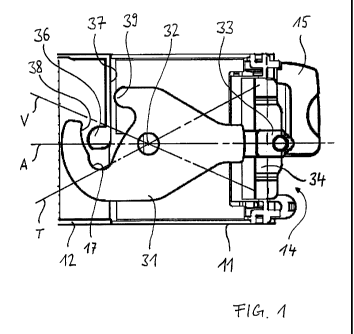
Figure 1 shows an embodiment of an arrangement according to the invention with
a
CA 02831989 2013-10-01
6
plug 11 and a complementary mating plus 12 for creating and/or detaching a
connection
between the plug 11 and the mating plug 12. A lever 31 pivoted around a shaft
32 is
arranged on the plug 11. In the design example shown, the plug 11 has a
generally
replaceable switch module, especially a trigger module, which ideally
interacts with a
circuit breaker, whereby the circuit breakers forms the mating plug 12. The
lever 31
with a longitudinal shaft A is shown in an interim position, in which the
connection
between plug 11 and mating plug 12 is neither created nor detached. The lever
31 can
be adjusted with the actuation grip 33, whereby the adjustment path is limited
by a
coulisse 34, in which the actuation grip 33 is guided to one actuation side 14
of the plug
11. If the lever 31 is pivoted into a detaching position T, in which the shaft
A lies more
or less along the line marked T, the fact that a projection 39 is provided on
the lever 31
enables the connection of the plug 11 with the mating plug 12 to be detached
by
transferring force from the projection 39 onto the mating plug 12. The
transfer of force
from the projection 39 onto the mating plug 12 preferably takes place directly
onto a
housing 37 of the mating plug 12. The lever 31 is especially designed as a
flat
component, which is essentially oriented in parallel to a housing wall of the
plug 11 or
the mating plug 12.
The lever 31 also has a connection contour 38 and the mating plug 12 has a
spigot 36,
whereby the connection of the plug 11 with the mating plug 12 can be created
by
pivoting the lever 31 into a connecting position according to the line marked
V. When
pivoting the lever 31 into the connecting position V, the shape of the
connection
contour 38 results in a transfer of force from the connection contour 38 onto
the spigot
36, by which the plug 11 and the mating plug 12 move towards one another, say,
over a
stretch of 4 millimetres, whereby the region of greatest force is overcome. An
engagement recess 17 arranged behind the connection contour 38 in the pivot
direction
towards the connecting position V advantageously allows an additional
engagement of
the lever 31 when the connection between the plug 11 and mating plug 12 is set
up, by
engaging the spigot 36 in the engagement recess 17.
A rotary knob 15 on the circuit breaker 12 will be described later in greater
detail in
connection with the figures 3 and 4.
CA 02831989 2013-10-01
7
Figure 2 shows a partial perspective view of the arrangement according to
Figure 1 on
the actuation side 14 of the plug 11. The mating plug 12 is visible in the
background.
The coulisse 34 serves to guide the actuation grip 33 of the lever 31, most of
which is
covered. At both its end positions, the coulisse 34 has engagement means 35,
which
allow engaging the actuation grip 33 in the connecting position or the
detaching
position. The plug 11 has a pivoted cover 20, which can cover the actuation
side 14 in
its closed state at least partially. Figure 2 shows the cover 20 in an opened
position. A
lock 21 with side ramps 22 prevents the cover 20 from closing as long as the
actuation
grip 33 is outside the end positions. A tab 23 helps to engage the cover 20
with the
mating plug 12 in the closed position, as explained below in connection with
Figure 3.
Figure 3 shows another perspective view of the actuation side 14, with the
cover in a
nearly closed position, from which it can also be inferred that the lock 21
would collide
with the actuation grip 33 if it is not positioned in one of the end
positions. This
advantageously prevents the cover 20 from being closed when the state of the
connection between the plug 11 and the mating plug 12 is unclear. Only if the
cover 20
is closed can the rotary knob 15 on the mating plug 12 once again rotate to
its switched-
on position. Furthermore, the mating plug 12 has a counter tab 16 for engaging
with the
tab 23 on the cover 20, by which the cover 20 is secured in the closed
position,
especially for as long as the rotary knob 15 is not shifted to the switched-on
position. In
the switched-on position, the rotary knob 15 rises over the cover 20 and
likewise
secures it in the closed position.
Figure 4 shows a cross-section view according to Figure 1, whereby the region
of the
coulisse 34 on the plug 11 is visible in as an enlarged partial view. The
cover 20 is in
the closed position. Here, the function of the ramps 22 on the web-shaped lock
21,
which is provided for shifting the actuation 33 into one of the end positions,
only in
case it is nearly in one of the end positions when closing the cover 20,
whereby on the
one hand, a certain tolerance range is advantageously created, and on the
other hand, the
deviation is comprehensively corrected by the ramp 22. Finally, the ramps 22
or the
lock 21 also cause a locking of the lever 31 in the locking position or in the
detaching
position, as long as the cover 20 remains closed.
. CA 02831989 2013-10-01
8
List of reference symbols
11 Plug, especially trigger module
12 Mating plug, especially circuit breaker
14 Actuation side
Rotary knob
16 Counter tab
17 Engagement recess
Cover
10 21 Lock
22 Ramp
23 Latch
31 Lever
32 Shaft
15 33 Actuation grip
34 Coulisse
35 Engagement means
36 Spigot
37 Housing of mating plug
20 38 Connection contour
39 Projection
A Shaft
T Detaching position
V Connecting position