Language selection

Search

Patent 2832048 Summary

Third-party information liability

Some of the information on this Web page has been provided by external sources. The Government of Canada is not responsible for the accuracy, reliability or currency of the information supplied by external sources. Users wishing to rely upon this information should consult directly with the source of the information. Content provided by external sources is not subject to official languages, privacy and accessibility requirements.

Claims and Abstract availability

Any discrepancies in the text and image of the Claims and Abstract are due to differing posting times. Text of the Claims and Abstract are posted:

  • At the time the application is open to public inspection;
  • At the time of issue of the patent (grant).
(12) Patent: (11) CA 2832048
(54) English Title: WATERPROOF ASSEMBLY FOR A LIGHT STRING
(54) French Title: ENSEMBLE ETANCHE POUR GUIRLANDE LUMINEUSE
Status: Granted
Bibliographic Data
(51) International Patent Classification (IPC):
  • H01R 13/52 (2006.01)
  • F21S 4/26 (2016.01)
  • F21V 23/06 (2006.01)
  • F21V 31/00 (2006.01)
(72) Inventors :
  • ZHAO, QINGEN (China)
(73) Owners :
  • SHANDONG NEON KING ELECTRONICS CO., LTD. (China)
(71) Applicants :
  • SHANDONG NEON KING ELECTRONICS CO., LTD. (China)
(74) Agent: CAMERON IP
(74) Associate agent:
(45) Issued: 2017-04-25
(22) Filed Date: 2013-11-06
(41) Open to Public Inspection: 2015-05-05
Examination requested: 2014-01-08
Availability of licence: N/A
(25) Language of filing: English

Patent Cooperation Treaty (PCT): No

(30) Application Priority Data:
Application No. Country/Territory Date
14/072,249 United States of America 2013-11-05

Abstracts

English Abstract

A waterproof light string assembly that comprises two ends that join to complete a circuit. The first end comprises an electrical male conducting element encased within a protective nodule. A second end comprises a protruding sheath having a female conducting element disposed therein and a configuration that accepts a portion of the nodule when said male element enters the sheath. The assembly is designed such that electrical elements are protected from ambient matters such as water and provide improved connectivity.


French Abstract

Un ensemble chaîne lumineuse étanche qui comprend deux extrémités qui se rejoignent pour fermer un circuit. La première extrémité comprend un élément conducteur mâle électrique logé dans un module de protection. Une seconde extrémité comprend une gaine saillante comportant un élément conducteur femelle disposé à lintérieur de celle-ci et une configuration qui accepte une partie du module lorsque ledit élément mâle entre dans la gaine. Lensemble est conçu de manière que les éléments électriques soient protégés contre les matières ambiantes, comme leau, et assurent une connectivité améliorée.

Claims

Note: Claims are shown in the official language in which they were submitted.

WHAT IS CLAIMED IS:
1. A waterproof light rope assembly comprising:
a male component having a proximal end and a recessed portion extending
inwards from said proximal end, the recessed portion of the male component
having an outer end diameter adjacent to said proximal end, the male component

housing a portion of an electrical conducting pin; and
a female component having a proximal end, the female component having an
opening at said proximal end of the female component for receiving the male
component, the female component including an internal area therein having a
base
spaced-apart from the proximal end of the female component, and the female
component including at least one sheath extending outwards from said base, the
at
least one sheath being disposed within said internal area, being received by
said
recessed portion of the male component, receiving the pin, housing a portion
of an
electrical contact designed to communicate with said pin, and having an outer
end
diameter, the outer end diameter of the at least one sheath being greater than
the
outer end diameter of the recessed portion of the male component.
2. The assembly of claim 1 further comprising a cap slidably engaged with a
portion
of said male component, and configured to secure said male component to said
female component.
6

3. The assembly of claim 2 further comprising a collar disposed about a
periphery of
said male component, the collar being distal to the proximal end of the male
component, wherein the collar engages a portion of the cap to act as a stop to

prevent the cap from disconnecting from the male component.
4. The assembly of claim 1 wherein the assembly further includes an o-ring
extending about the male component, and wherein the female component has an
extension formed about the opening of the female component, whereby, when the
female component is joined with the male component and secured therein, the
extension contacts the o-ring, preventing passage of unwanted material
therethrough thereby.
5. The assembly as claimed in claim 1, wherein the recessed portion of the
male
component has an inner end, an outer end, the outer end diameter of the
recessed
portion being adjacent to the outer end of the recessed portion, and a
diameter
between the inner and outer ends of the recessed portion, the outer end
diameter
of the at least one sheath being less than the diameter of the recessed
portion of
the male component between the inner and outer ends of the recessed portion.
6. The assembly as claimed in claim 1 wherein the at least one sheath
includes a
deformable material.
7

7. The assembly as claimed in claim 1 wherein the at least one sheath has
an outer
end, the outer end diameter of the at least one sheath being adjacent to said
outer
end of the at least one sheath, and wherein the at least one sheath includes a

deformable material at least at said outer end of the at least one sheath.
8. A waterproof light rope assembly comprising:
a female connector having an internal area defined by a rim disposed about an
opening at one end and an internal base opposite said opening;
a conduit extending outwards from said base of the female connector, the
conduit
containing therein a portion of an electrical contact and the conduit having
an
outer end diameter;
a male connector having a proximal end; and
an electrical conducting pin recessed within said male connector, the
conducting
pin being accessible by an opening extending inwards from the proximal end of
said male connector, the opening of the male connector having a diameter, the
outer end diameter of the conduit being greater than the diameter of the
opening
of the male connector and said conduit being sized and shaped to enter the
opening of said male connector, and enter a sufficient distance such that said
pin
is in sufficient proximity to said electrical contact.
8

9. The assembly of claim 8 wherein when said pin is in sufficient proximity
to said
electrical contact, a portion of said male connector is within said internal
area
defined by said female connector.
10. The assembly of claim 8 further comprising a cap that connects said
male
connector and said female connector together.
11. The assembly of claim 8 wherein said male connector has a periphery and

includes an o-ring disposed about said periphery, the o-ring abutting said rim
to
prevent passage of unwanted material therebetween.
12. The assembly of claim 10 wherein a collar is formed about a periphery
of said
male connector, the collar functioning as a stop for said cap.
13. The assembly of claim 12, wherein said cap includes internal threading
that
corresponds to threading formed about an exterior surface of said female
connector, such that when the male connector and the female connector are
joined, the cap may be tightened for securing connection of the male connector

with the female connector.
14. The assembly of claim 11 wherein a collar is formed about a periphery
of said
male connector, the collar housing said o-ring and providing a boundary for
the o-
9

ring such that when said o-ring deforms, the o-ring sufficiently fills said
boundary
such that unwanted material is unable to pass therethrough.
15. The assembly as claimed in claim 8 wherein the conduit includes a
deformable
material.
16. The assembly as claimed in claim 8 wherein the conduit has an outer
end, the
outer end diameter of the conduit is adjacent to said outer end of the
conduit, and
wherein the conduit includes deformable material at least at said outer end
thereof.
17. A waterproof light rope assembly comprising:
a male connector having a first end, a second end spaced-apart from the first
end,
the second end of the male connector engaging to a portion of a first light
string,
and a recessed portion extending inwardly from said first end towards said
second
end, the recessed portion housing an electrical conducting pin and the
recessed
portion having an outer end diameter adjacent to said first end of the male
connector;
a female connector having a first end and a second end spaced-apart therefrom,

the second end of the female connector engaging to a portion of a second light

string, the female connector including a rim that defines an opening at said
first

end of the female connector, the opening being shaped to receive the male
connector at least in part, and the female connector having an internal area
extending inwardly from the first end of the female connector, the internal
area of
the female connector being in communication with the opening of the female
connector and being defined by an internal base therein; and
a sheath encasing an electrical contact, being disposed within said internal
area,
extending from said base towards the opening of the female connector,
receiving
the pin, and having an outer end diameter spaced-apart from said internal
base, the
outer end diameter of the sheath being greater than the outer end diameter of
the
recessed portion of the male connector.
18. The assembly of claim 17 further wherein said first end of said female
connector
is sized and shaped to accept said male connector and provide transmission of
an
electrical charge therebetween.
19. The assembly of claim 17 wherein the male connector includes an
internal wall
inwardly spaced from the first end of the male connector, the internal wall
being
in communication with the recessed portion of the male connector, wherein the
sheath has an opening through which the pin is received, and wherein the
sheath
includes a wall adjacent to said opening of the sheath, the sheath being
shaped
such that said wall of the sheath is frictionally engageable with the internal
wall of
the male connector, preventing passage of unwanted material thereby.
11

20. The assembly of claim 17 further comprising:
a cap slidingly engaged to said male connector and configured to connect the
male
connector and the female connector together; and
a collar disposed around a periphery of the male connector distal to the first

end of the male connector, the collar functioning as a stop for the cap.
21. The assembly of claim 20 wherein an o-ring is disposed about said
collar, such
that when the male connector and the female connector are combined, the o-ring

is contacted by said rim and the rim deforms the o-ring thereby and prevents
passing of unwanted material therethrough.
22. The assembly as claimed in claim 17, wherein the recessed portion of
the male
connector has an outer end to which the outer end diameter thereof is
adjacent, an
inner end, and a diameter between the outer and inner ends of the recessed
portion, the outer end diameter of the sheath being less than the diameter of
the
recessed portion of the male connector between the outer and inner ends of the

recessed portion.
23. The assembly as claimed in claim 17 wherein the sheath includes a
deformable
material.
12

24. The
assembly as claimed in claim 17 wherein the sheath has an outer end and
includes deformable material at least at said outer end of the sheath.
13

Description

Note: Descriptions are shown in the official language in which they were submitted.


CA 02832048 2016-06-10
Agent's Ref. 6772P01CA
WATERPROOF ASSEMBLY FOR A LIGHT STRING
BACKGROUND OF THE INVENTION
Field of the Invention
[0001] The present invention generally relates to lighting and connections,
in
particular, the present invention relates to an assembly for a light string
that has
waterproof characteristics and improved connectivity.
Description of the Related Art
[0002] Waterproof and/or water resistant assemblies for light strings are
known. For
example, U.S. Pat. No. 6,893,144 (Fan) discloses an assembly, of which
reference is
incorporated herein. Fan discloses a female connector having two holes (23)
that
correspond to a male connector having two pins (13) as shown in Fan FIG. 1.
Fan
identifies Fan FIG. 5 as prior art, which too provides a female connector
having two holes
(611) that correspond to a male connector having two pins (55). Upon
comparison of Fan
FIG. 1 with Fan FIG. 5 prior art, it is obvious that Fan merely fuses cited
prior art cover
(67) to cited prior art shoulder (63) and removes cited prior art threading
(671) and (531).
Next, to accomplish the goal of Fan FIG. 1, Fan simply adds a cap to the cited
prior art
first body (51) shown in Fan FIG. 5 and disposes new threading.
[0003] Fan (U.S. Pat. No. 6,893,144) and the prior art cited therein,
provide same
configurations. As a result, the configuration of Fan and the Fan cited prior
art are not
enough to protect the electrical connection for similar reasons Fan asserts as
failure of
prior art. Additionally, the pins provided in both Fan and the Fan cited prior
art are
exposed and capable of being compromised, affecting integrity of electrical
connections.

CA 02832048 2016-06-10
The instant invention overcomes deficiencies of prior art and provides an
improved
waterproof assembly with improved connectivity.
BRIEF SUMMARY OF INVENTION
[0004] The current invention provides an assembly that comprises a first
portion
having at least one female electrical connection housed within a protective
sheath that
extends out from an internal base enclosed by an outer casing. A second
portion consists
of a plug having at least one male electrical connection recessed in a chamber
formed
therein, that when the male and female portions are combined, the protective
sheath
surrounds both male and female connections at the same time and encased
forming an
airtight and waterproof barrier. The resulting connections provide better
connectivity and
protect the male electrical connections from being damaged.
BRIEF DESCRIPTION OF DRAWINGS
[0005] The invention may take physical form in certain parts and
arrangement of
parts, some embodiments of which will be described in the specification and
illustrated in
accompanying drawings which form a part hereof, wherein:
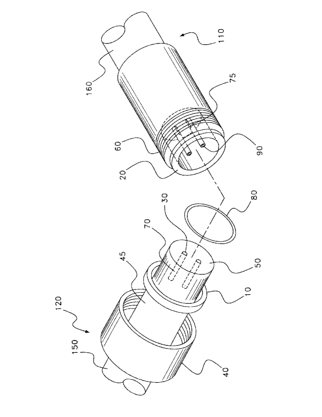
[00061 FIG. 1 is an exploded perspective view of the assembly;
[00071 FIG. 2 is a cross sectional view of the assembly when disconnected;
[00081 FIG. 3 is a cross sectional view of the assembly when connected and
showing
engagement between male and female components.
2

CA 02832048 2016-06-10
DESCRIPTION OF THE PREFERRED EMBODIMENTS
[0009] According to an embodiment of the invention as shown in FIG. 1, a
male
component 120 is provided and being referenced to that of a plug. Said
component 120
has a first end that comprises housing 50 and a second end engaged to a
portion of a first
light string 150. Housing 50 is shown as cylindrical but is not limited to a
particular
geometry, so long as a portion thereof is capable of entering an internal area
or opening
85 formed within the female component 110. The male component 120 further
comprises
neck 45 that is the intermediary between electrical wires (not shown) and male
electrical
connections or pins 70 and which may provide as guide for cap 40, which may be

slidingly engaged thereto. Male component 120 and female component 110 may be
comprised substantially of a non-electrical conductive material such as
plastic, or an
insulated material otherwise, and may be formed by processes not limited to
molding, 3-
D printing, boring, and/or other known means.
[0010] Collar 10 is disposed around a periphery of the male component 120.
As show
in FIG. 1, collar 10 is located distal to housing 50, distal to the first end
of the male
component 120, and proximal to said neck 45. The location of collar 10 may
however be
located in other areas about the male component 120, so long as it serves as a
stop for cap
40 and/or provides housing for o-ring 80, which may include any deformable
material
capable of preventing passage of unwanted material. While only a single collar
10 is
provided, it is within the scope of the invention that there be multiple
collars, for
example, a collar may be disposed about the second end of said male component
120
(i.e., distal to neck 45) and used to act as a stop for cap 40 and a second
collar may be
disposed proximal thereto (i.e. closer to the first end of said male component
120) and
house o-ring 80.
[0011] Extending in a proximal direction from collar 10 is housing 50
located at
about the first end of male component 120. As shown, housing 50 comprises two
holes or
recessed portions 30 extending distal from its opening and having a depth, li.
As provided
3

CA 02832048 2016-06-10
in FIG. 2, recessed portions 30 encase pins 70 recessed therein and referred
to as pin,
which may originate and/or extend from base 130 of recessed portion 30 and
have a
length equal to about 11. The length of pins 70 may be equal or askew to each
depending
on configuration of a corresponding receptor or sheath 90 to be explained
further. The
length of pin 70 may be in the range of greater than 0.0111 to about 11. As
shown in FIG.
2, length of pins 70 is about equal to each and about 0.9011. Said pin 70 is
designed to
communicate an electrical charge between said male component 120 and female
component 110 when in contact with (or sufficient proximity to) female contact
or
electrical connection 75.
[0012] Female component 110 has an opening 85 defined by rim 20 located at
a first,
proximal end of the female component 110, and is connected to a second light
rope 160 at
its second end. Said opening 85 leads to an internal area formed within the
female
component 110 that extends therein (i.e., distal) and is further defined by
base 152 and at
least one wall that has a length, 12, as measured from proximal end of rim 20
to base 152.
The female component 110, which could be referred to as a socket, further
comprises an
outer shell consisting of threading 60 disposed on a portion of an exterior
surface. As
shown, threading 60 is in a location proximal to a smooth region 100 and
distal to said
rim 20.
[0013] As shown, rim 20 forms a perimeter about opening 85. Said opening 85
is
shaped and sized to accept housing 50. Extending out and/or in a proximal
direction from
base 152 is a conduit and/or sheath 90. The length of the sheath 90 may be
about less than
or equal to 12. As shown in FIG. 2, length of sheath 90 is about 0.8512.
Sheath 90 houses
and/or is formed around female electrical connection 75 and provides
protection to said
connection as well as a guide for pin 70. As seen in Figure 2, each sheath 90
has an inner
end 91 coupled to base 152, an outer end 95 spaced-apart from the inner end
and adjacent
to rim 20 in this example, an outer end diameter d3 adjacent to the outer end
thereof, and
an diameter d4 inwardly spaced from outer end diameter d3 and outer end 95 of
the sheath.
As seen in Figure 2, recessed portion 30 has an opening or outer end 31, an
outer end
diameter di adjacent to said outer end, an inner end 33 aligned with base 130
and a
4

CA 02832048 2016-06-10
diameter d2 between the inner and outer ends of the recessed portion. In an
embodiment,
d3 is greater than di but less than d2 such that when sheath 90 enters
recessed portion 30
the outer end 95 of sheath 90 can frictionally engage with an interior wall of
recessed
portion 30 and act as a barrier to passage of unwanted material, for example
water. In this
embodiment, sheath 90 may comprise a deformable material, at least at its
outer end 95.
[0014] FIG. 3 is a
cross sectional view of the assembly showing the engagement
between the male component/connector 120 and female component/connector 110.
As
shown, sheath 90 surrounds pin 70 which is in electrical communication with
female
contact 75. Cap 40 internal threading is combined with threads 60. In
practice, when cap
40 is tightened thereto, this compresses o-ring 80 preventing passage of
unwanted
materials such as liquid and/or gas. As shown, when the male component 120 and
female
component 110 are engaged and/or connected, and cap 40 threads to 60, rim 20
is drawn
to o-ring 80. When cap 40 is tightened and/or secured thereto, rim 20 causes o-
ring 80 it
to deform and fill void therein to prevent passage of unwanted materials such
as liquid
and/or gas. The interaction further acts as an airtight and/or waterproof
barrier therein.

Representative Drawing
A single figure which represents the drawing illustrating the invention.
Administrative Status

For a clearer understanding of the status of the application/patent presented on this page, the site Disclaimer , as well as the definitions for Patent , Administrative Status , Maintenance Fee  and Payment History  should be consulted.

Administrative Status

Title Date
Forecasted Issue Date 2017-04-25
(22) Filed 2013-11-06
Examination Requested 2014-01-08
(41) Open to Public Inspection 2015-05-05
(45) Issued 2017-04-25

Abandonment History

There is no abandonment history.

Maintenance Fee

Last Payment of $204.00 was received on 2021-11-05


 Upcoming maintenance fee amounts

Description Date Amount
Next Payment if small entity fee 2022-11-07 $100.00
Next Payment if standard fee 2022-11-07 $277.00

Note : If the full payment has not been received on or before the date indicated, a further fee may be required which may be one of the following

  • the reinstatement fee;
  • the late payment fee; or
  • additional fee to reverse deemed expiry.

Patent fees are adjusted on the 1st of January every year. The amounts above are the current amounts if received by December 31 of the current year.
Please refer to the CIPO Patent Fees web page to see all current fee amounts.

Payment History

Fee Type Anniversary Year Due Date Amount Paid Paid Date
Application Fee $400.00 2013-11-06
Request for Examination $800.00 2014-01-08
Maintenance Fee - Application - New Act 2 2015-11-06 $100.00 2015-11-06
Maintenance Fee - Application - New Act 3 2016-11-07 $100.00 2016-11-02
Final Fee $300.00 2017-03-10
Maintenance Fee - Patent - New Act 4 2017-11-06 $100.00 2017-11-02
Maintenance Fee - Patent - New Act 5 2018-11-06 $200.00 2018-08-21
Maintenance Fee - Patent - New Act 6 2019-11-06 $200.00 2019-08-15
Maintenance Fee - Patent - New Act 7 2020-11-06 $200.00 2020-11-05
Maintenance Fee - Patent - New Act 8 2021-11-08 $204.00 2021-11-05
Owners on Record

Note: Records showing the ownership history in alphabetical order.

Current Owners on Record
SHANDONG NEON KING ELECTRONICS CO., LTD.
Past Owners on Record
None
Past Owners that do not appear in the "Owners on Record" listing will appear in other documentation within the application.
Documents

To view selected files, please enter reCAPTCHA code :


To view images, click a link in the Document Description column. To download the documents, select one or more checkboxes in the first column and then click the "Download Selected in PDF format (Zip Archive)" or the "Download Selected as Single PDF" button.

List of published and non-published patent-specific documents on the CPD .

If you have any difficulty accessing content, you can call the Client Service Centre at 1-866-997-1936 or send them an e-mail at CIPO Client Service Centre.


Document
Description 
Date
(yyyy-mm-dd) 
Number of pages   Size of Image (KB) 
Abstract 2013-11-06 1 13
Description 2013-11-06 6 197
Claims 2013-11-06 5 117
Drawings 2013-11-06 3 60
Representative Drawing 2015-03-25 1 15
Cover Page 2015-04-13 1 42
Claims 2015-09-09 6 155
Description 2016-06-10 5 187
Claims 2016-06-10 8 192
Drawings 2016-06-10 3 59
Representative Drawing 2017-06-21 1 25
Maintenance Fee Payment 2017-11-02 1 33
Maintenance Fee Payment 2018-08-21 1 33
Maintenance Fee Payment 2019-08-15 1 33
Assignment 2013-11-06 3 86
Prosecution-Amendment 2014-01-08 1 33
Prosecution-Amendment 2015-03-10 4 234
Amendment 2015-09-09 16 461
Fees 2015-11-06 1 33
Examiner Requisition 2015-12-10 4 267
Amendment 2016-06-10 32 872
Fees 2016-11-02 1 33
Final Fee 2017-03-10 1 35
Cover Page 2017-03-24 1 42