Note: Descriptions are shown in the official language in which they were submitted.
CA 02832361 2013-10-04
, .
Motor vehicle door lock housing
Description:
Then invention relates to a motor vehicle door lock housing with at least one
outwardly
facing recess for receiving electric strip conductors, and with passages in
the recess for
connecting the strip conductors to the housing interior.
Such motor vehicle door lock housings generally consist of several parts and
typically
comprise a metal lock case and an actual plastic lock housing or a plastic
cover or a plastic
housing body. Said recess is located in the actual plastic lock housing. The
recess faces
outwards and can thus receive one or several strip conductors from the
outside. As a result,
the basic motor vehicle door lock and the motor vehicle door lock housing can
be produced
after which the strip conductors are arranged in the recess only at the end.
The recess is
sealed with a sealing compound in order to protect the strip conductors
against corrosion or
environmental influences.
The generic state of the art of WO 2010/136004 Al discloses that the strip
conductors are
placed as printed or stamped conductor screens in the recess and are connected
to
electric/electronic components located in the housing interior. This
arrangement has
generally proven to be successful but could be improved as regards the
required assembly
and production, as nowadays, manufacturers often use standardised components,
which
require, for instance, for different strip conductors or strip conductor
structures to be
accommodated in the motor vehicle door lock housing. Prior art arrangements
have so far
not produced any convincing solutions in this respect.
The invention is based on the technical problem of further developing such a
motor vehicle
door lock housing in such a way that it can be universally used and that
assembly/manufacture is simplified.
To solve this technical problem, a generic motor vehicle door lock housing as
part of the
invention is characterized in that the strip conductors with at least one
strip conductor
board, on which they re arranged, can be positioned in the recess.
As part of the invention, the strip conductors are thus expressly not
positioned in the recess
as printed or stamped conductor screens according to WO 2010/136004 Al.
Instead, the
invention uses a strip conductor board carrying the strip conductors. This
strip conductor
board generally contains feet on the housing side. It has proven to be
advantageous for the
feet to be designed as strip conductor extensions. The feet or the strip
conductor extensions
of the strip conductor board engage in each case in individual passages in the
recess. As a
result, the strip conductor board is centred inside the recess and the feet
designed as strip
conductor extensions also ensure that the strip conductors carried by the
strip conductor
board can assume the desired electrical connection with the
electric/electronic components
provided in the housing interior.
1
CA 02832361 2013-10-04
The chosen design may consequently such that the feet on the housing side of
the strip
conductor board engage in respective plug receptacles in the housing interior.
Said plug
receptacles can be mechanical plug receptacles, if the feet on the housing
side are non-
conductive. Generally, the feet on the housing side are, however, strip
conductor extensions
extending mainly at right angles from the underside of the strip conductor
board. In this
case, the plug receptacles are electrical plug receptacles, i.e. those that
provide a direct
electric contact as soon as the feet designed as strip conductor extensions
engage in said
electric plug receptacles. Individual electric/electronic components in the
housing interior of
the motor vehicle door lock housing can be connected to the electric plug
receptacles.
Typically the inside of a motor vehicle door lock housing contains one or
several electric
motors, individual sensors, micro switches, etc., required for the operation
of the motor
vehicle door lock or that monitor individual functional positions of the motor
vehicle door
lock.
The strip conductor board can generally be any type of strip conductor board,
i.e. a printed
board with single or multiple layer, typically produced from an insulation
material. The strip
conductors are defined on such a strip conductor board by chemical and or
physical
processes. Also, the top of the strip conductor board, i.e. the upper side
facing the housing
feet on the bottom, can contain electric/electronic components. In particular
electronic
SMD components (surface-mounted device) have proven to be advantageous. This
is
naturally only an example and not mandatory.
The strip conductor board with its feet on the housing side protruding from
its base, is
normally applied to one or several supports of the recess. The recess
consequently contains
one or several supports for the strip conductor board. The one or several
supports are
typically a continuous frame. Alternatively or in addition, the support or the
frame can also
be designed as a seal.
Such an embodiment has shown to be particularly advantageous where the strip
conductor
board closes off the recess in the manner of a cover. In this case, the plane
internal cross
section of the recess and the plane extension of the strip conductor board are
typically
adapted to each other in such a way that the strip conductor board can be
positively
accommodated in the recess, on which one or several supports rest, as a result
of which the
recess is closed off in the manner of a cover. The casting compound
subsequently applied to
the strip conductor board or filled into the recess can consequently easily
seal the recess. In
most cases, the casting compound will be mainly arranged between a surface or
top side of
the strip conductor board and the edge at the head of the recess. As regards
application of
the casting compound, only a thin layer of casting compound is, on the other
hand, applied
to the area from the bottom surface or base of the strip conductor board up to
the base of
the recess. In this way the quantity of casting compound for each recess to be
sealed can be
considerably reduced compared to previous embodiments. The described design is
therefore particularly cost effective.
2
CA 02832361 2013-10-04
. .
Also, the strip conductor board including the strip conductors and any
additionally installed
electric/electronic components defines or can define a pre-assembled
subassembly. Ideally,
the motor vehicle door lock including all levers, assemblies, etc. to be
arranged in the
housing interior is fully assembled and enclosed by the motor vehicle door
lock housing of
the invention. The electric/electronic components arranged inside the motor
vehicle door
lock housing are then controlled and electrically connected by the strip
conductor board or
the already preassembled subassembly being inserted in the recess. During the
process the
thus provided strip conductor board or strip conductor board with the strip
conductors
arranged thereon or possible electric/electronic components, uses the one or
several
supports inside the recess for positioning.
This ensures that the feet or strip conductor extensions can extend directly
through the
associated passages in the recess and engage on the other side of the passages
and in the
housing interior in the provided plug receptacles. This means that the
positioning of the
preassembled subassembly or of the printed circuit board or strip conductor
board in the
recess also ensures that the strip conductors on the strip conductor board are
electrically
connected with the associated and desired assemblies in the housing interior.
No other
work is required. As soon as the preassembled subassembly or the strip
conductor board is
positioned in the recess, the recess and the strip conductor board can be
sealed by said
casting compound.
In other words, no complicated installation work is required and instead, the
pre-installed
subassembly or strip conductor board only has to be placed in the recess with
this process
also providing the required electric contact. To complete the process, the
strip conductor
board is sealed in the recess, so that the motor vehicle door lock housing of
the invention is
directly ready for use and prepared for installation. These are the main
advantages.
In another advantageous embodiment, the support for the strip conductor board
or the pre-
installed subassembly is provided at an edge of the recess. It has also shown
too be
particularly advantageous if the height of the support in question in
connection with, where
applicable, the height of the equipped and supported strip conductor board is
equal to or
thinner than the depth of the recess. This ensures that the strip conductor
board resting on
the support or any components on said board do not exceed the edge on the head
of the
recess or do not "protrude". The casting compound applied after assembly of
the strip
conductor board then ensures that the strip conductor board is completely or
nearly
completely covered by the casting compound or that no components protruding
over the
edge on the head of the recess are visible.
Of further significance is the fact that the passages in the recess describe a
hole pattern
adapted to the strip conductor board inserted in the recess. In other words,
each strip
conductor board inserted in the recess corresponds to a special hole pattern
of the passages
in the recess. In order to achieve a particular standardized manufacture and
to allow, where
possible, the use of the same door lock housing for different door lock
designs, it has further
3
CA 02832361 2013-10-04
proven to be advantageous for the recess to be designed for receiving
different printed
circuit boards. It is for instance feasible that the same door lock housing is
used to
accommodate a motor vehicle door lock with central locking and a motor vehicle
door lock
without central locking.
Both types, i.e. with and without central locking or with opening and closing
assistance
naturally require different strip conductor boards, as for instance in the
central locking
model a central locking motor has to be controlled, the position of a central
locking lever
has to be sensed, etc. Naturally, none of these described functions are
required for a motor
vehicle door lock without central locking functions. Consequently, the
respective strip
conductor board for the central locking model tends to have considerably more
feet on the
housing side to provide the contact for subassemblies contained in the housing
interior
compared to models without central locking.
In order to, however, be able to accommodate both models of the example in the
recess or
in the same motor vehicle door lock housing, all strip conductor board hole
patterns
correspond to a universal hole pattern of the passages in the recess. This
means that the
strip conductor board placed in the recess defines its own strip conductor
board hole
pattern or a pattern of the feet on the housing side on the strip conductor
board. All strip
conductor boards placeable in the recess and the respective strip conductor
board hole
patterns thus define a universal hole pattern, typically implemented in the
recess.
This universal hole pattern is characterized in that in general feet on the
housing side of the
strip conductor board inserted in the recess do not extend through all
openings or passages.
Instead more or fewer passages remain uncovered during this process. Only when
inside of
the motor vehicle door lock housing contains a lock, fulfilling all
conceivable functions, also
all passages of the universal hole pattern are "occupied" by the associated
feet on the
housing side.
In this way, manufacture and assembly is simplified even more as different
types of the
motor vehicle door lock can be accommodated in the same motor vehicle door
lock housing.
This also applies to the strip conductor board belonging to the respective
motor vehicle
door lock, as the outwardly facing recess, accommodating the strip conductor
board, is
universally designed for receiving the respective strip conductor board. This
simplifies
positioning and also assembly is significantly easier than before. At the same
time resources
are saved as the required quantity of casting compound is significantly
reduced compared to
prior art embodiments.
Below, the invention is described in more detail with reference to a drawing
showing only
one embodiment, in which:
Fig. 1 shows a schematic overview of the motor vehicle door lock housing
according to the
invention
4
CA 02832361 2013-10-04
Fig. 2 shows a cross section of the object of Fig. 1.
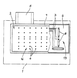
Fig. 1 shows a motor vehicle door lock housing containing first of all a
housing body 1 made
of plastic. Apart from this plastic housing body 1 a metal lock case is
typically provided. This
is, however, not shown. Together, the metal lock case and the plastic housing
body 1 make
up the motor vehicle door lock housing. Of special significance for the below
observations is
an outwardly facing recess 2 on this motor vehicle door lock housing. The
recess 2 serves to
receive electric strip conductors 3. Also, passages 4 are provided in the in
the recess 2. The
strip conductors 3 are connected to the housing interior by means of the
passages 4 in the
recess 2. This is schematically shown in the sectional view of Fig. 2. The
housing interior
contains motors, sensors, plug-in contacts, etc. connected via the strip
conductors 3. For
this purpose, the strip conductors 3 produce an electric connection to a
socket 5 in the
example. A plug, not shown, can be connected to the socket 5, which in turn
ensures the
electric connection of the shown motor vehicle door lock to, for instance, a
control unit
inside a motor vehicle.
In this embodiment and according to a preferred embodiment of the invention,
the strip
conductors 3 together with the strip conductor board 6 accommodating the strip
conductors 3, is placed in the recess. This means that in the embodiment,
strip conductors 3
are arranged on the strip conductor board 6, as electrically conductive
conductors that are,
for instance, printed or applied by any other process onto the strip conductor
board 6. The
strip conductor board 6 is also provided with feet 7 on the housing side,
providing an
electric connection to the individual strip conductors 3. The feet 7 on the
housing side
extend more or less vertically from a base U of the strip conductor board 6,
as clearly shown
in the cross sectional view of Fig. 2. The top 0 of the strip conductor board
6 can contain
electric/electronic parts 8. The so-called SMD technology has proven to be
particularly
advantageous in this respect.
In this way, the strip conductor board 6 including the electric/electronic
components 8 and
the feet 7 on the housing side can be produced together as a preassembled
subassembly 6,
7, 8. This preassembled subassembly 6, 7, 8 can be positioned in the recess 2.
For this
purpose, the recess 2 contains one or several supports 9 also best apparent
from the
sectional view of Fig. 2. The support 9 in the example is indeed a frame 9,
provided at an
edge of the recess 2.
For this purpose, the support 9 has, as shown in Fig. 2, a height H1, which
together with a
height H2 of the strip conductor board 6 and its components resting on the
support 9 or the
height H2 of the subassembly 6, 7, 8 corresponds to a depth T of the recess 2
or is smaller
than said depth. According to the invention, the following relation does thus
apply:
H1 + H2S <T.
As, furthermore, the area of the strip conductor board 6 matches the area of
the recess 2 or
the strip conductor board 6 sits predominantly flush in the recess 2, this
explains that the
CA 02832361 2013-10-04
strip conductor board 6 seals the recess 2 like a cover, as soon as it rests
on the supports 9.
Indeed it is ensured in this way that the casting compound 10 is mainly
located between the
surface or top 0 of the strip conductor board 6 and an edge 11 on the head of
the recess 2.
In contrast, an area between the base U of the strip conductor board 6 and a
base 12 of the
recess 2 only contains a thin layer of casting compound 10.
The recess 2 is arranged on the plastic housing body 1 and typically forms a
single plastic
piece with the housing body 1 and is moulded in the body. The same applies to
the supports
9 or the edge 9.
The recess 2 or the housing body 1 made of plastic are consistently retained
even if different
embodiments of the respective implemented door lock are positioned in the
interior of the
housing. It is for instance feasible that the same motor vehicle door lock
housing is used to
accommodate a motor vehicle door lock with central locking or a motor vehicle
door lock
without central locking in its interior.
As, in addition, the openings or passages 4 in the recess 2 describe a hole
pattern 13
adapted in each case to a strip conductor board 6 inserted in the recess 2, it
is clear that
depending on the level of equipment of the door lock (with or without central
locking) also
different preassembled subassemblies (6, 7, 8) are used. These different
preassembled
subassemblies 6, 7, 8 correspond to adapted and varied hole patterns 13. This
means that
the recess 2 is designed for receiving different strip conductor boards 6 or
different
preassembled subassemblies 6, 7, 8.
The individual corresponding hole patterns 13 are now part of the associated
preassembled
subassembly 6, 7, 8 or the associated strip conductor board 6. This results in
a strip
conductor board hole pattern 13, ultimately defined by the arrangement of the
feet 7 on
the housing side, extending (having to extend) through the associated passages
4.
All different strip conductor board hole patterns 13 now define a universal
hole pattern 14
of the passages 4 in the recess 2. This universal hole pattern 14 is arranged
and designed in
such a way, that any conceivable type of the motor vehicle door lock
accommodated inside
of the motor vehicle door lock housing can be accommodated, with each
respective type
being associated with a preassembled subassembly 6, 7, 8. This arrangement is
made
possible as the recess 2 is sealed by the strip conductor board 6 or the
preassembled
subassembly 6, 7, 8 in the manner of a cover and by the casting compound 10
basically
being predominantly arranged between the surface or top 0 of the strip
conductor board 6
and the edge 11 at the head of the recess 2. It is virtually impossible for
casting compound
to enter unassigned passages 4 and thus the inside of the housing.
As soon as the preassembled subassembly 6, 7, 8 or the strip conductor board 6
is
positioned in the recess 2 on the frame 9, the feet 7 on the housing side
engage in the plug
receptacles 15 in the housing interior. During this process, the feet 7 on the
housing side
extend through individual or all passages 4 in the recess 2. In the
embodiment, the plug
6
CA 02832361 2013-10-04
, .
,
receptacles 15 are designed as electrical plug receptacles 15 and are
connected to the
assemblies inside the housing by means of conductors. In this way, the
subassembly 6, 7, 8
positioned inside the recess 2 directly provides the required electrical
connection from the
bushing 5 through the strip conductors 3 up to the assemblies in the housing
interior to be
controlled or scanned.
7