Note: Descriptions are shown in the official language in which they were submitted.
CA 02832417 2017-01-25
WALL INSULATION SYSTEMS WITH STANCHION
CROSS-REFERENCE TO RELATED APPLICATIONS
[0001] This application claims the benefit of U.S. Provisional Application
No.
61/472,400 filed April 6,2011.
BACKGROUND OF THE INVENTION
1. Field of the Invention
10002 The invention relates generally to the field of constructing
buildings. More
specifically, the invention relates to the field of fabricating insulated
metal walls for
metal buildings.
2. Description of the Related Art
[0003] Conventionally, metal buildings are constructed according to a
series of
steps. First, a metal frame is constructed. The metal frame includes numerous
structural
support members. The roof portions include sloped roof structural members
referred to
as purlins. The walls include vertically spaced horizontally extending
members, which
are referred to as girts. Once the frame is installed, it is common to
insulate both the roof
and wall portions of the building.
[0004] With respect to roof arrangements, blanket insulation is draped over
the tops
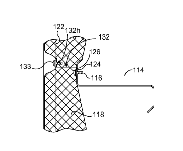
of the purlins, and then roof panels are fastened over the insulation. In some
cases, it has
been known to install a longitudinal thermal block above the top flange of the
purlin
such that it runs the entire length of the purlin over the draped blanket
insulation.
[0005] With respect to the conventional wall, blanket insulation is secured
from
above such that it is draped over horizontally extending girts. Then metal
wall panels are
fastened to the outer flanges of the girts, mashing the blanket insulation
between the
wall panel and the outer flange of each girt where they interface. These lines
of mashed
down insulation create heat losses.
SUMMARY
[0006] In embodiments, the invention is a wall system that is structurally
supported
by vertically displaced horizontal support members (e.g., gifts). In
embodiments, the
system includes a wall panel of the kind having inwardly-extending
1
CA 02832417 2017-01-25
channels. In a first embodiment a bracket is installed between the girts and
wall panel. Each
bracket has a plurality of tabs. The tabs are spaced apart from one another on
the bracket,
and extend laterally outward. Portions of each tab are configured to secure
the bracket
between the wall panel and the vertically displaced horizontal support member.
In a second
alternative embodiment, independent tabs (not on a bracket) can be spaced
apart along each
of the horizontal support members. Regardless, space is created between the
outer flanges
of the girts and inwardly-extending channels on the wall panel. This space
allows a blanket
of insulation to be expanded into space created between the tabs.
[0007] A method for fabricating a wall is also disclosed. The method
includes (i)
providing a plurality of vertically spaced, horizontally extending structural
members, (ii)
draping insulation outside of the horizontally extending structural members,
(iii) fastening
connector portions on laterally extending tabs on a plurality of bracket
members over the
blanket insulation into a plurality of outer flanges of each of the plurality
of horizontally
extending structural members, and (iv) installing a wall panel outside of the
insulation by
fastening the wall panel to an outer flange on the bracket.
BRIEF DESCRIPTION OF THE SEVERAL VIEWS OF THE DRAWINGS
[0008] Illustrative embodiments of the present invention are described in
detail below
with reference to the attached drawing figures, and wherein:
[0009] FIG. lA shows a cross-sectional wall section of a conventional
insulated panel;
[0010] FIG. IB shows a top view of a horizontal section taken from a
conventional
insulated metal building wall design;
[0011] FIG. 1C is a broken out section showing the specifics around a girt
for the
conventional design shown in Figs. lA and IB;
[0012] FIG. ID is a perspective view of an exemplary wall panel;
[0013] FIG. 2 shows a perspective view of an insulated wall according to
the invention
disclosed herein;
[0014] FIG. 3A is a perspective view of a stanchion bracket in line with
the teachings
of the present invention;
[0015] FIG. 3B shows a flat metallic piece that can be machined to make the
stanchion
bracket of FIG. 3A;
2
CA 02832417 2013-10-04
WO 2012/138449
PCT/US2012/028582
[0016] FIG. 3C shows an end view of the stanchion bracket of FIG. 3A;
[0017] FIG. 4A shows a vertical section taken from the insulated wall
of the
present invention;
[0018] FIG. 4B shows a horizontal section taken from the insulated
wall of the
present invention;
[0019] FIG. 4C shows a broken out section taken from the vertical
section of
FIG. 4A;
[0020] FIG. 4D shows a broken out section taken from the horizontal
section
taken from FIG. 4B;
[0021] FIG. 5A shows a perspective view of a spacer tab in line with
the
teachings of the present invention; and
[0022] FIG. 5B shows an end view of the spacer tab of FIG. 5A.
DETAILED DESCRIPTION
[0023] Embodiments of the present invention provide an insulated
metal panel
system for insulating a building. To provide context for the disclosed
embodiments,
consider FIGs. 1A, 1B, 1C, and 1D which show the current state of the art.
[0024] FIG. 1A shows a conventional system 10 wherein a metal wall
panel
12 is installed to create a building wall. The type of paneling shown in FIGs.
1A-D is
referred to by the trade name SHADOWALL and is manufactured by BlueScope
Butler
located in Kansas City, Missouri, a business group of BlueScope Steel Limited,
Australia.
As shown in FIG. 1D, the wall panel 12 may include vertical channels (or
ridges) 22 that
run up and down the panel 12. These vertical channels 22 constitute the inner
most part
of the panel 12, i.e., these channels 22 extend towards the building interior
the furthest
(see FIG. 1B). Between each of these vertical channels 22 a subtle V-dip 20
also extends
in the same direction as the channels (ridges) 22 (see FIG. 1D).
[0025] As shown in FIG. 1A, this type of metal panel 12 is commonly
fastened to a plurality of horizontally running and vertically spaced Z-girts
14. Each Z-
girt 14 has an outer flange 24 (see FIG. 1C) to which, using fasteners 16, the
metal wall
panel 12 is fastened. The fasteners 16 typically are self-tapping screws.
[0026] When it is desirable to insulate the wall, a blanket of
insulation 18 may
be unrolled and draped down the wall panel 12 before the panel 12 is secured
to the Z-
gilts 14. The blanket of insulation 18 may have a facing 19 on the inside,
which prevents
3
CA 02832417 2013-10-04
WO 2012/138449
PCT/US2012/028582
contact with inhabitants, presents a more appealing look, and creates a vapor
barrier. The
draping process may involve tacking the blanket 18 in some manner to the
uppermost
purlin so that it remains in an unfurled position. After being unrolled and
draped down
the panel 12, the blanket of insulation 18 is secured between the wall panel
12 and the
outer flanges 24 of the plurality of Z-girts 14 using the fasteners 16 (see
FIG. 1A). More
specifically, the fasteners 16 are driven through the vertical channels 22,
the blanket of
insulation 18, and then into the outer flanges 24 of the Z-girts 14.
[0027] When a fastener 16 is screwed through the inner most portion
(channel
22) of the wall, it presses against the outer flange 24 of the corresponding Z-
girt 14, and
sandwiches a portion 26 of the blanket of insulation 18 (see FIG. 1C). This
compacting
of the blanket of insulation 18 creates an area where the thermal resistance
is weakened,
which allows for considerable heat losses. If one were to look at the heat
flow diagrams
in the area near the flange 24 of Z-girt 14, one would see significant flow of
heat energy
through the area surrounding the fastener 16. Conversely, one would note that
the heat
losses are reduced at locations spaced above or below the flanges 24 of the Z-
girts 14.
This reduction in heat loss at the inter-girt positions is because the blanket
of insulation
18 (for example, halfway between the vertically spaced Z-girts 14 in FIG. 1 A)
billows
and fluffs outward the further it is from the girt flanges 24, allowing for
more air, which
is a good insulator of heat, to aid in the insulation. As the blanket of
insulation 18 is
pinned between the inside surface of the channels 22 and the girt flange 24 at
numerous
locations in the panel 12, the resulting heat loss would appear as a plurality
of vertically
displaced parallel horizontal stripes on the outside of each wall of the
building so
configured.
[0028] The arrangement disclosed by the current invention 110,
which can
be seen in FIGs. 2 through 5, greatly reduces heat losses in a metal wall 112
(see FIG. 2).
As with the conventional system 10, the metal wall 112 is attached outside Z-
girts 114 of
the building using fasteners. Also, like the conventional system 10, when the
wall 112 is
mounted, a blanket of insulation 118 having a facing 119 is draped down and
installed
between the wall 112 and the Z-girt 114. Further, akin to the conventional
system 10, the
new system 112 is fastened at innermost channel portions 122 of the wall 112
(see FIG.
2).
[0029] But the new system 110 is different from the conventional
system in
that the blanket of insulation 118, upon securing the metal wall panel 112, is
not directly
4
CA 02832417 2013-10-04
WO 2012/138449
PCT/US2012/028582
pressed and sandwiched between the metal wall panel 112 and the flange 124 of
the Z-
girt 114. Instead, a laterally extending stanchion bracket 132 (see FIG. 2) is
installed over
the insulation 118 and is fastened between the wall panel 112 and outer flange
124 of the
Z-girt 114 along the length of the girt 114.
[0030] The stanchion bracket 132, as shown more clearly in FIG. 3A,
comprises a laterally extending support bar 134 and plurality of tabs 126
spaced along the
length of the support bar 134. Each tab 126 has an outwardly extending portion
126a
which extends outward from the support bar 134 and terminates at an edge 126b.
The
edge 126b of the outwardly extending portion 126a constitutes that part of the
outwardly
extending portion 126a which is furthest away from the support bar 134. Each
tab 126
further comprises a downwardly extending portion 126c that extends downward
from the
edge 126b.
[0031] The stanchion bracket 132 may be constructed from a flat
metallic
piece 131 (see FIG. 3B) that is configured, by known methods, to form the
finished
stanchion bracket 132. Some or all of the tabs 126, within their downwardly
extending
portions 126c, may include openings or holes 126h. The support bar 134 may
also have
holes 132h that are laterally spaced along the support bar 134 at a distance
1321, which
distance 1321 generally corresponds to a lateral distance between two
vertically extending
adjacent channels 22 (see measurement 221 in FIG. 1D).
[0032] In terms of assembly in the erection of the building, the Z-
girts 114
will already be in place as shown in the figures, and the remaining wall
components will
be installed outside them. In some embodiments, the blanket of insulation 118
will be
draped over the outside of flanges 124 of the Z-girts 114. It is not necessary
to
independently fasten the insulation 118 at this point, but in many instances,
it will make
sense to secure the blanket 118 from above and allow it to drape down outside
the girt
flanges 124 before securing the wall panel 112 to the Z-girts 114.
[0033] The next step, in embodiments, involves securing the stanchion
brackets 132. In some embodiments, this would mean that the tabs 126 of the
stanchion
bracket 132 are secured to the flange 124 of the Z-girt 114 on top of the
insulation 118
before the wall panel 112 is secured to the support bar 134 of the bracket
132. After the
tabs 126 are aligned and fixed such that they extend along the length of the Z-
girt 114,
fasteners 116 (see FIG. 4C) are passed through the holes 126h in the tabs 126
and the
blanket of insulation 118, and made to bite into the flange 124 of the Z-girt
114. The
CA 02832417 2013-10-04
WO 2012/138449
PCT/US2012/028582
portions of insulation trapped underneath the tabs 126 of the stanchion 132
are relatively
small, and after they are secured to the girt flange 124, the surrounding
insulation easily
puffs outward to fill all the areas surrounding the tabs 126. Care may be
taken to
horizontally align the tabs 126 along the flange 124 in such a way that at
least one
channel 122 of the panel 112, when the panel 112 is subsequently installed,
corresponds
to a hole 132h in the support bar 134 of the bracket 132.
[0034] The next step, after the tabs 126 are secured to the flange
124 via
fasteners 116, is to stand the panel 112 upright such one or more channel
portions 122 of
the panel 112 align with the hole 132h in the support bar 134 of the bracket
132.
Specifically, fasteners 133 (see FIG. 4C) are passed through the channel 122
from the
outside, and then passed through hole 132h in the support bar 134. The panel
112,
thereby, is indirectly secured to the flange 124 of the Z-girt 114.
[0035] Because the outwardly extending portions 126a of the tabs 126
displace the panel 112 from the outer flange 124 of the Z-girt 114,
significant open space
is created between the girt 114 and the panel 112 so that the insulation 118
can fill the
space. Moreover, each tab 126 is laterally spaced from an adjacent tab 126 by
a distance
130 (see FIG. 4B), and a bracket 132 is vertically spaced from another bracket
132 by a
considerable distance 128 (See FIG. 4A). These distances create more area for
the
blanket of insulation 118 to fluff out into, both between the vertically
spaced Z-girts 114,
and also into the lateral spaces 130 between adjacent tabs 126. Fluffed
blanket insulation
118 is far more effective as a heat barrier than insulation 118 that is matted
down. Thus,
a much higher percentage of the wall panel 112 is backed by insulation that is
billowed
rather than matter down, and consequently, heat losses are greatly reduced
because of the
stanchion brackets 132.
[0036] It is also possible to achieve the objectives stated above by
using,
instead of or along with the stanchion bracket 132, a plurality of independent
tabs 200a
(see FIGs. 5 and 5B) that are laterally spaced along the length of the outer
flange 124 of
the Z-girt 114. In this embodiment, the tab 200a has a base member 202a having
edges
204a and 206a. A connector portion 208a having an opening or hole 208h extends
vertically upward from the edge 204a, whereas a connector portion 210a having
an
opening or hole 210h extends vertically downward from the edge 206a. The tabs
200a
are first secured to the flange 124 of the Z-girt 114 over the insulation 118
by a fastener
that extends through the hole 210h in the connector portion 210a, and then
bites into the
6
CA 02832417 2013-10-04
WO 2012/138449
PCT/US2012/028582
flange 124 of the Z-girt 114. As before, in terms of horizontal placement of
the tabs 200a
along the flange 124, care may taken that the tabs 200a are secured to the
flange 124 in
such a way that the holes 208h in the connector portion 208a correspond with
channel
portions 122. After the tabs 200a are secured to the flange 124, the panel 112
may be
stood upright and secured to the connector portions 208a of the tabs 200a;
specifically, a
fastener may be passed, from the outside of the channel 122, through the
channel 122 and
the hole 208h of the connector 204a, thereby indirectly securing the panel 112
to the
flange 124 of the Z-girt 114. These independent tabs 200a may allow for
greater
flexibility than the stanchion bracket 132, as any number of tabs 200a can be
secured and
spaced as desired in line the requirements of a particular project.
[0037] Many different arrangements of the various components
depicted, as
well as components not shown, are possible without departing from the spirit
and scope
of the present invention. Embodiments of the present invention have been
described with
the intent to be illustrative rather than restrictive. Alternative embodiments
will become
apparent to those skilled in the art that do not depart from its scope. A
skilled artisan may
develop alternative means of implementing the aforementioned improvements
without
departing from the scope of the present invention.
[0038] It will be understood that certain features and
subcombinations are of
utility and may be employed without reference to other features and
subcombinations and
are contemplated within the scope of the claims. Not all steps listed in the
various figures
need be carried out in the specific order described.
7