Note: Descriptions are shown in the official language in which they were submitted.
SYNGAS COOLER SYSTEM AND METHOD OF OPERATION
A process and system is provided for cooling syngas. More specifically, syngas
is
blended with cooled recycled syngas to provide a blended syngas. The blended
syngas is
subsequently transferred to a syngas cooler.
BACKGROUND
Microorganisms can produce ethanol and other compounds from carbon monoxide
(CO) through fermentation of gaseous substrates, The CO is often provided to
thc
fermentation as part of a gaseous substrate in the form of a syngas.
Gasification of
carbonaceous materials to produce producer gas or synthesis gas or syngas that
includes
carbon monoxide and hydrogen is well known in the art. Typically, such a
gasification
process involves a partial oxidation or starved-air oxidation of carbonaceous
material in
which a sub-stoichionictric amount of oxygen is supplied to the gasification
process to
promote production of carbon monoxide.
Syngas produced by gasification processes described in the art can be hot and
needs cooling prior to downstream processing and subsequent fermentation. Hot
syngas
comprising carbon monoxide generated in a gasification apparatus, is cooled in
a heat
exchanger or waste heat boiler downstream of the gasification apparatus, see
for example
US Patent No. 6,435,139; US Patent No. 7,587,995 and US Patent No. 7,552,701.
Effective and controlled cooling of syngas is important in minimizing fouling.
SUMMARY
A process and system for cooling syngas provides effective syngas cooling and
results in reduced levels of fouling in syngas cooling equipment. In one
aspect, a process
for cooling syngas includes blending syngas with cooled recycled syngas in an
amount
effective for providing a blended syngas with a temperature at an inlet of a
syngas cooler
of about 600 F to about 1400 F. The blended syngas changes direction of flow
at least
once prior to the inlet of the syngas cooler.
In another aspect, a syngas mixing system includes a gasification chamber
having a
diameter Da and a syngas recycle inlet having a diameter Dc. The syngas
recycle inlet
enters the gasification chamber at a distal end of the gasification chamber.
The system
includes a gasification outlet having a diameter Dm. The gasification outlet
is continuous
CA 2832434 2018-07-20
CA 02832434 2013-10-04
WO 2012/138762
PCT/US2012/032174
with the distal end of the gasification chamber and the gasification outlet
including at least
one change of direction prior to entering a syngas cooler.
In another aspect, a process for cooling syngas includes blending syngas with
cooled recycled syngas in an amount effective for providing a blended syngas
with a
temperature at an inlet of a syngas cooler in the range of about 6000F to
about 1400 F.
The cooled recycled syngas is supplied to a distal end of a gasification
chamber having a
diameter Dut through a syngas recycle inlet having a diameter Dc, and Dc/DH is
about 0.25
to about 0.75.
BRIEF DESCRIPTION OF FIGURES
The above and other aspects, features and advantages of several aspects of the
process will be more apparent from the following drawings.
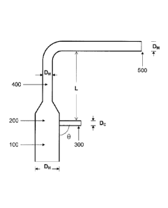
Figure 1 illustrates a syngas mixing system.
Figure 2 shows a bottom view of a syngas mixing system.
Corresponding reference characters indicate corresponding components
throughout
the several views of the drawings. Skilled artisans will appreciate that
elements in the
figures are illustrated for simplicity and clarity and have not necessarily
been drawn to
scale. For example, the dimensions of some of the elements in the figures may
be
exaggerated relative to other elements to help to improve understanding of
various aspects
of the present process and apparatus. Also, common but well-understood
elements that are
useful or necessary in commercially feasible aspects are often not depicted in
order to
facilitate a less obstructed view of these various aspects.
DETAILED DESCRIPTION
The following description is not to be taken in a limiting sense, but is made
merely
for the purpose of describing the general principles of exemplary embodiments.
The scope
of the invention should be determined with reference to the claims.
The syngas cooling process and system are operated at temperatures effective
for
providing effective syngas cooling and reduced fouling of equipment. Design of
the
system provides effective syngas mixing.
Definitions
Unless otherwise defined, the following terms as used throughout this
specification
for the present disclosure are defined as follows and can include either the
singular or
plural forms of definitions below defined:
2
CA 02832434 2013-10-04
WO 2012/138762
PCT/US2012/032174
The term "about" modifying any amount refers to the variation in that amount
encountered in real world conditions, e.g., in the lab, pilot plant, or
production facility. For
example, an amount of an ingredient or measurement employed in a mixture or
quantity
when modified by "about" includes the variation and degree of care typically
employed in
measuring in an experimental condition in production plant or lab. For
example, the
amount of a component of a product when modified by "about" includes the
variation
between batches in a multiple experiments in the plant or lab and the
variation inherent in
the analytical method. Whether or not modified by "about," the amounts include
equivalents to those amounts. Any quantity stated herein and modified by
"about" can also
be employed in the present disclosure as the amount not modified by "about".
"Carbonaceous material" as used herein refers to carbon rich material such as
coal,
and petrochemicals. However, in this specification, carbonaceous material
includes any
carbon material whether in solid, liquid, gas, or plasma state. Among the
numerous items
that can be considered carbonaceous material, the present disclosure
contemplates:
carbonaceous material, carbonaceous liquid product, carbonaceous industrial
liquid
recycle, carbonaceous municipal solid waste (MSW or msw), carbonaceous urban
waste,
carbonaceous agricultural material, carbonaceous forestry material,
carbonaceous wood
waste, carbonaceous construction material, carbonaceous vegetative material,
carbonaceous industrial waste, carbonaceous fermentation waste, carbonaceous
petrochemical co products, carbonaceous alcohol production co-products,
carbonaceous
coal, tires, plastics, waste plastic, coke oven tar, fibersoft, lignin, black
liquor, polymers,
waste polymers, polyethylene terephthalate (PETA), polystyrene (PS), sewage
sludge,
animal waste, crop residues, energy crops, forest processing residues, wood
processing
residues, livestock wastes, poultry wastes, food processing residues,
fermentative process
wastes, ethanol co-products, spent grain, spent microorganisms, or their
combinations.
The term "fibersoft" or "Fibersoft" or "fibrosoft" or "fibrousoft" means a
type of
carbonaceous material that is produced as a result of softening and
concentration of
various substances; in an example carbonaceous material is produced via steam
autoclaving of various substances, in another example, the fibersoft can
include steam
autoclaving of municipal, industrial, commercial, and medical waste resulting
in a fibrous
mushy material.
The term "municipal solid waste" or "MSW" or "msw" means waste that may
include household, commercial, industrial and/or residual waste.
3
The term "syngas" or "synthesis gas" means synthesis gas which is the name
given
to a gas mixture that contains varying amounts of carbon monoxide and
hydrogen.
Examples of production methods include steam reforming of natural gas or
hydrocarbons
to produce hydrogen, the gasification of coal and in some types of waste-to-
energy
gasification facilities. The name comes from their use as intermediates in
creating
synthetic natural gas (SNG) and for producing ammonia or methanol. Syngas is
combustible and is often used as a fuel source or as an intermediate for the
production of
other chemicals.
In one aspect, gasification of carbonaceous materials provides syngas.
Gasification
0 involves partial combustion of biomass in a restricted supply of oxygen.
The resultant gas
includes CO and H2. In this aspect, syngas will contain at least about 20 mole
% CO, in
one aspect, about 20 to about 100 mole A CO, in another aspect, about 30 to
about 90
mole A CO, in another aspect, about 40 to about 80 mole % CO, and in another
aspect,
about 50 to about 70 mole % CO. The syngas will have a CO/CO2 ratio of at
least about
0.75, Serial Numbers 61/516,667, 61/516,704 and 61/516,646 describe some
examples of
suitable gasification methods and apparatus (U.S Serial Numbers 61/516,667,
61/516,704
and 61/516,646, all of which were filed on April 6,2011).
Syngas leaving the gasifier will have a temperature above about
1400 F, and in another aspect, at least about 1400 F to about 3500 F. The
gasification
process is effective for destruction of tars.
Syngas Cooling System
As shown in Figure 1, the gas mixing system includes a gasification chamber
100.
A syngas recycle inlet 300 enters a distal end or exit section of the
gasification chamber
200. In this aspect, the syngas recycle inlet 300 enters the distal end 200 of
the gasification
chamber 100 at an outer circumference. The gasification inlet 300 enters the
distal end of
the gasification chamber 200 tangentially and may be at an angle (shown as 0)
of about 15
to about 165 , in another aspect, about 30 to about 150 , in another aspect,
about 45 to
about 135 , in another aspect, about 60 to about 120 , in another aspect,
about 75 to about
105 , and in another aspect, about 85 to about 95 .
Hot syngas leaving the gasifier 100 contacts recycled cooled syngas through a
syngas recycle inlet 300. The recycled cooled syngas contacts the hot syngas
at a point
after the hot syngas leaves the gasifier and before the blended syngas enters
a syngas
cooler (not shown) through a gasification outlet 400. The gasification outlet
400 may be a
4
CA 2832434 2018-07-20
CA 02832434 2013-10-04
WO 2012/138762
PCT/US2012/032174
conduit or pipe. In this aspect, "recycled cooled syngas" refers to a syngas
that has been
cooled in a syngas cooler to a temperature of about 350 F to about 450 F.
The process includes blending recycled cooled syngas with hot syngas at a
ratio of
about 0.1 to about 20. In other aspects, ratios of recycled cooled syngas to
hot syngas may
include about 1 to about 15, about 1 to about 10, about 1 to about 5, about 1
to about 4,
about 1 to about 3, about 1 to about 2, and about 1 to about 1,
The blended syngas has a temperature of about 1400 F or less, in another
aspect,
about 600 F to about 1400 F, in another aspect, about 750 F to about 1400 F,
in another
aspect, about 600 F to about 1400 F, in another aspect, about 750 F to about
1200 F, in
another aspect, about 750 F to about 900 F, in another aspect, about 750 F to
about
825 F, and in another aspect, about 600 F to about 900 F. In this aspect, a
thermal couple
measures temperature at an inlet of the syngas cooler 500. The thermal couple
may be
positioned at any position across a diameter of the inlet of the syngas cooler
500.
As used herein, "average temperature" refers to known methods utilized to
determine multiple temperatures across a diameter and then express those
multiple
temperature measurements as an average. In one aspect, computer modeling may
be used
to provide an average temperature. In other aspects, multiple temperatures may
be made
using thermocouples equipped for such measurements, infrared sensing and the
like.
Temperature, flow rates and configuration of the syngas cooler are effective
for
preventing flow of recycled cooled syngas and blended syngas into the
gasification
chamber 200. In this aspect, flow through the syngas cooler is greater than
about 24 meters
per second.
As further shown in Figure 1, the distal end of the gasification chamber 200
is
continuous with a gasification outlet 400. The gasification outlet 400 may
change direction
at least once before entering a syngas cooler. As shown in Figure 1, the
gasification outlet
400 changes direction once at a 90 angle. In this aspect, the gasification
outlet 400 may
change direction at least once, with any change of direction each
independently being at an
angle of about 15 to about 165 .
As illustrated in Figure 1, the gasification chamber 200 has a diameter of
the
syngas recycle inlet 300 has a diameter of Dc, and the gasification outlet 400
has a
diameter of Dm. The syngas recycle inlet 300 is located a distance (L) away
from the
gasification outlet 400. Ratios of measurements may be as follows:
Dc/DH: about 0.25 to about 0.75, in another aspect, about 0.35 to about 0.65,
and in
5
CA 02832434 2013-10-04
WO 2012/138762
PCT/US2012/032174
another aspect, about 0.45 to about 0.55;
L/DH: about 1 to about 10, in another aspect, about 3 to about 8, and in
another
aspect, about 4 to about 6; and
Dti/Dm: about 0.5 to about 2.0, in another aspect, about 0,75 to about 1.75,
and in
another aspect, about 1.0 to about 1.5.
In another aspect, the syngas recycle inlet 300 may have a diameter of about
32 to
about 42 inches, in another aspect, about 34 to about 40 inches, and in
another aspect,
about 35 to about 38 inches. The gasification outlet 400 may have a diameter
of about 40
to about 52 inches, in another aspect, about 43 to about 49 inches, and in
another aspect,
about 45 to about 47 inches.
Figure 2 illustrates a bottom view of the syngas cooling system. In this
aspect, the
syngas recycle inlet 300 enters the gasification chamber 100 at an outer
circumference 600
of the gasification chamber,
In another aspect, the syngas recycle inlet 300 enters the gasification
chamber 100
at a point above the gasification chamber 100 and initial gas mixing occurs at
a point
above the gasification chamber 100. In this configuration, any deposits formed
may fall
back down into the gasification chamber 100.
EXA'NIPLES
Example 1: Effect of Syngas Cooler Inlet Temperature on Heat Transfer and
Fouling
A gasifier having the design described herein was operated with the
temperatures
and flow rates described below. A fouling factor was determined as indicated.
Fouling factor at 600 F inlet temperature to the syngas cooler:
Accumulated Temperature of Syngas at Syngas Feed Fouling
Factor Fouling
Time (hrs) Inlet of Syngas Cooler ( F) Rate to Cooler Btu/ (ft2h
F) Factor
(lb/hr)
_____ 7.7 601 _________ 477 0.022 45
15.7 614 512 0.034 29
23.7 = 597 862 0.009 115
31.7 608 730 0.008 132
40 605 1647 0.002 444
56 597 432 0,023 43
_____ 64.7 _________ 593 705 0.011 __ 92
72 577 618 1 0.014 70
80 595 596 j 0.019 52
89 577 1416 0.007 149
188.15 583 35J 0.006 164
_____ 196 572 372 0.024 41
___________ 207.7 __ = ____________ 565 __ 345 j 0.048 21
216 577 317 0.034 29
223.7 572 385 0.024 41
6
CA 02832434 2013-10-04
WO 2012/138762 PCT/US2012/032174
Average fouling factor at 600 F inlet was 0.019 Btu/(ft2h F).
A gasifier having the design described herein was operated with lower syngas
cooler inlet temperatures and flow rates described below. A fouling factor was
determined
as indicated.
Fouling factor at 1300 F inlet temperature to the syngas cooler:
Accumulated Temperature of ' Syngas Feed Fouling Factor
Fouling Factor i
Time (hrs) Syngas at Inlet of Rate to Cooler Btu/ (ft2h
F) .
Syngas Cooler ( F) (lb/hr) ,
7.5 1297 288 0.042 23.6
19.5 1293 314 0.070 i 14.3 _..._
105.5 1295 215 0,119 8.4
_______ 118.5 1295 230 0.100 10
_
129.5 1294 194 0.123 8.1
153.5 1297 ______________________ 191 0.098 10.2
. ,
166.5 1295 198 . 0.096 10.4
...._
177.5 1295 233 0.072 13.8
190.5 1297 209 1111111111 10.1
260.5 1308 240 0.050 20.2
273.5 1302 214 0.067 14.9
_______ 285.5 1301 183 0,082 12.2
298.5 1295 .229 0.073 12,8
309.5 1296 264 0.080 12.5
31-7 1314 240 __ 0.097 10,3
326.5 1328 275 0.078 12.8
338.83 1322 291 0.068 14.8
_______ 346.5 1332 281 _____ 0.070 14.3 __
350.5 1346 _____ 312 0.071 14
368.5 1336 213 0.081 12.3
374.5 1335 253 I __ 0. 0 74 ___ 13.6
Average fouling factor at 1300 F inlet was 0.078 Btu/(ft2h 11).
While the invention herein disclosed has been described by means of specific
embodiments, examples and applications thereof, numerous modifications and
variations
could be made thereto by those skilled in the art without departing from the
scope of the
invention set forth in the claims.
7