Note: Descriptions are shown in the official language in which they were submitted.
CA 02832717 2013-10-08
WO 2012/141974 PCMJS2012/032360
1
SYSTEM AND METHOD FOR .................... PROCESSING
REACTOR POLYMERIZATION EFFLUENT
FIELD OF THE INVENTION
[0001] This disclosure generally relates to a system for processing an
effluent stream from a
polymerization reaction process. Particularly, the disclosure relates to
removing one or more
undesired components and recycling one or more reusable components from a
polymerization
reaction effluent stream.
BACKGROUND OF THE INVENTION
[0002] The production of polymers such as polyethylene requires a high purity
feedstock of
various components, including monomers and co-monomers. In order to offset
some of the costs
and maximize production, it can be useful to reclaim and/or recycle some
feedstock components
from an effluent stream resulting from the polymerization reaction. To
accomplish this, the
reclaimed effluent streams have conventionally either been routed through a
purification process or
redirected through other redundant processing steps.
[0003] Conventional attempts to industrially produce high purity feedstock
components has
required the operation of numerous distillation columns, compressors (e.g., to
achieve the high
pressures needed in such conventional processes), refrigeration units (e.g.,
to achieve cryogenic
temperatures) and various other equipment. As such, the equipment and energy
costs associated
with feedstock purification represent a significant proportion of the total
cost for the production of
such polymers. Further, the infrastructure required for producing,
maintaining, and recycling high
purity feedstock represents a significant portion of the associated cost.
[0004] Further, such conventional attempts to recover feedstock components
have not enabled
sufficient control parameters to prevent and/or control deleterious plant
conditions. The drawbacks
of these designs can lead to process delays, increased costs, and/or other
inefficiencies. As such,
an improved separation system for polymerization reaction effluent streams is
needed.
SUMMARY OF THE INVENTION
[0005] Disclosed herein is a method of treating a polymerization reactor
effluent stream
comprising recovering the reactor effluent stream from the polymerization
reactor, flashing the
81519380
2
reactor effluent stream to form a flash gas stream, separating the flash gas
stream into a first
top stream, a first bottom stream, and a side stream, wherein the side stream
substantially
comprises hexane, separating the first top stream into a second top stream and
a second
bottom stream, wherein the second bottom stream substantially comprises
isobutene, and
separating the second top stream into a third top stream and a third bottom
stream; wherein
the third top stream substantially comprises ethylene, and wherein the third
bottom stream is
substantially free of olefins.
[0006] Also
disclosed herein is a method of treating a polymerization reactor effluent
stream comprising recovering the effluent stream from the polymerization
reactor, flashing
the effluent stream to form a flash gas stream, feeding the flash gas stream
into a first column,
recovering a first overhead stream, a first bottom stream, and a side stream,
from the first
column, wherein the side stream substantially comprises hexane, feeding the
first overhead
stream into an accumulator vessel, recovering a second overhead stream and a
second bottom
stream from the accumulator vessel, wherein the second bottom stream
substantially
comprises isobutene, feeding the second overhead stream to a second column,
and recovering
a third overhead stream and a third bottom stream from the second column,
wherein the third
bottom stream is substantially olefin-free.
[0006a] Also disclosed herein is a method of treating a polymerization reactor
effluent
stream comprising: recovering the effluent stream from the polymerization
reactor; flashing
the effluent stream to form a flash gas stream; feeding the flash gas stream
into a first column;
recovering a first overhead stream, a first bottom stream, and a side stream,
from the first
column, wherein the side stream comprises hexene in an amount of from 20 % to
98 % by
total weight of the side stream; feeding the first overhead stream into an
accumulator vessel;
recovering a second overhead stream and a second bottom stream from the
accumulator
vessel, wherein the second bottom stream comprises isobutane in an amount of
from 70 % to
100 % by total weight of the second bottom stream; feeding the second overhead
stream to a
second column; and recovering a third overhead stream and a third bottom
stream from the
second column, wherein the third bottom stream comprises olefins in an amount
of less than
1.0 % by total weight of the third bottom stream.
CA 2832717 2018-10-25
81519380
2a
BRIEF DESCRIPTION OF THE DRAWINGS
[0007] Figure 1 is a block diagram of a polyethylene polymerization system,
according to
an embodiment of the disclosure.
[0008] Figure 2 is a flow diagram of a polyethylene production process,
according to an
embodiment of the disclosure.
[0009] Figure 3 is a block diagram of a polyethylene polymerization system,
according to
an embodiment of the disclosure.
DETAILED DESCRIPTION OF EMBODIMENTS
[0010] Disclosed herein are various embodiments of systems, apparatuses,
and methods
related to polymerization reactions, particularly, polyethylene
polymerization. The systems,
apparatuses, and methods are generally related to a process for the separation
and handling of
the effluent stream from a polyethylene polymerization process.
CA 2832717 2018-10-25
CA 02832717 2013-10-08
WO 2012/141974 PCT/US2012/032360
3
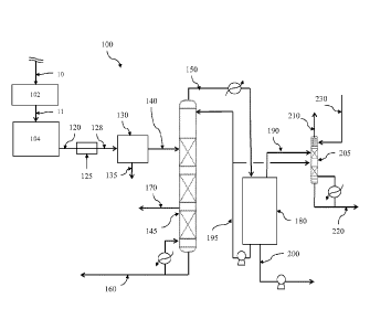
[0011] Referring to Figure 1, a first polyethylene production (PEP) system 100
is disclosed.
PEP system 100 generally comprises a purifier 102, reactor 104, a flash-line
heater 125, a flash
chamber 130, a first column 145, an accumulator 180, and a second column 205.
In the
embodiments disclosed herein, various such system components may be in fluid
communication
via one or more conduits (e.g., pipes, tubing, flow lines, etc.) suitable for
the conveyance of a
particular stream, for example as shown in Figure 1 by the streams which are
conveyed via such
conduits. In alternative embodiments, the same or similar equipment and/or
processes may be
employed for the production of other polymeric materials, for example
polypropylene,
polybutylene, polyvinylchloride, or the like.
[0012] Referring to Figure 2, a first PEP process 500 is illustrated. PEP
process 500 generally
comprises at block 50 purifying a feed stream, at block 51 polymerizing
monomers of the purified
feed stream in one or more reactors, at block 53 heating an effluent stream
from the one or more
reactors, at block 55 separating the heated effluent stream into a polymer
product stream and a
flash gas stream, at block 56 separating the flash gas stream into a first
overhead stream, a side
stream, and a first bottom stream, at block 58 recycling the side stream to
the one or more reactors,
at block 60 separating the first overhead stream into a second overhead stream
and a second
bottom stream, at block 62 recycling the second bottom stream to the one or
more reactors, at
block 64 separating the second overhead stream into a third overhead stream
and a third bottom
stream, and at block 68 recycling the third bottom stream to the one or more
reactors.
[0013] In an embodiment, the PEP process 500 or a portion thereof, may be
implemented via a
PEP system like PEP system 100 illustrated in Figure 1. In the embodiment of
FIG 1, purifying
the feed stream 10 in purifier 102 may yield a purified stream 11 comprising
substantially pure
monomers (e.g., ethylene monomers), as will be described herein. Polymerizing
monomers of the
purified stream 11 in the reactor 104 may yield an effluent stream 120
generally comprising
unreacted ethylene, ethane, diluent (e.g., one or more of propane, propylene,
isobutane, n-butane,
etc...), and a polymerization product (e.g., polyethylene). Heating the
effluent stream 120 in
heater 125 may yield a heated effluent stream 128. Separating the heated
effluent stream 128 in
flash chamber 130 may yield a polymer product stream 135 and a flash gas
stream 140. Separating
the flash gas stream 140 in first column 145 may yield a first overhead stream
150 generally
comprising C4 and smaller/lighter hydrocarbons, a first bottom stream 160
generally comprising C6
CA 02832717 2013-10-08
WO 2012/141974 PCT/US2012/032360
4
and larger/heavier hydrocarbons, and a side stream 170 generally comprising
hexene. Separating
the first overhead stream 150 in accumulator 180 may yield a second top stream
190 generally
comprising isobutane, ethylene, ethane, and/or other light hydrocarbons, and a
second bottom
stream 200 generally comprising isobutane, ethylene, and/or other
hydrocarbons. In an
embodiment as will be discussed herein the concentration of light hydrocarbons
(e.g., ethylene and
ethane) may be less in the second top stream 190 than in the second bottom
stream 200.
Separating the second top stream 190 in second column 205 may yield a third
overhead stream 210
comprising substantially ethylene, and a third bottom stream 220 generally
comprising olefin-free
isobutane.
[0014] Various embodiments of suitable PEP systems having been disclosed,
embodiments of a
PEP process are now disclosed. One or more of the embodiments of a PEP process
may be
described with reference to PEP system 100. Although a given PEP process may
be described
with reference to one or more embodiments of a PEP system, such a disclosure
should not be
construed as so-limiting. Although the various steps of the processes
disclosed herein may be
disclosed or illustrated in a particular order, such should not be construed
as limiting the
performance of these processes to any particular order unless otherwise
indicated.
[0015] In an embodiment, a feed stream is purified (e.g. at block 50).
Purifying the feed stream
may comprise separating unwanted compounds and elements from a feed stream
comprising
ethylene to form a purified feed stream. In embodiments illustrated by Figure
1, purifying the feed
stream may comprise routing the feed stream 10 to the purifier 102. In one or
more of the
embodiments disclosed herein, the purifier 102 may comprise a device or
apparatus suitable for the
purification of one or more reactant gases in a feed stream which may comprise
a plurality of
potentially unwanted gaseous compounds, elements, contaminants, or the like.
Non-limiting
examples of a suitable purifier 102 may comprise a filter, a membrane, a
reactor, an absorbent, a
molecular sieve, one or more distillation columns, fractionation columns, or
combinations thereof.
The purifier 102 may be configured to separate ethylene from a stream
comprising methane,
ethane, acetylene, propane, propylene, water, oxygen, other gaseous
hydrocarbons, various
contaminants, and/or combinations thereof
81519380
[0016] In an embodiment, purifying a feed stream may yield a purified feed
stream 11
comprising substantially pure ethylene. In an embodiment, the purified feed
stream may comprise
less than 25% by weight, alternatively, less than about 10%, alternatively,
less than about 1.0% of
any one or more of nitrogen, oxygen, methane, ethane, propane, other
hydrocarbons, or
combinations thereof. As used herein "substantially pure ethylene" refers to a
fluid stream
comprising at least about 60% ethylene, alternatively, at least about 70%
ethylene, alternatively, at
least about 80% ethylene, alternatively, at least about 90% ethylene,
alternatively, at least about
95% ethylene, alternatively, at least about 99% ethylene by weight,
alternatively, at least about
99.5% ethylene by weight. In an embodiment, the purified feed stream 11 may
further comprise
trace amounts of ethane.
10017] In an embodiment, monomers of the purified feed stream 11 may be
polymerized (e.g., at
block 51). Polymerizing monomers of the purified feed stream 11 may comprise
allowing a
polymerization reaction between a plurality of monomers by contacting a
monomer or monomers
with a catalyst system under conditions suitable for the formation of a
polymer. A suitable catalyst
system may comprise a catalyst and, optionally, a co-catalyst and/or promoter.
Non-limiting
examples of suitable catalyst systems include Ziegler-Natta catalysts, Ziegler
catalysts, chromium
catalysts, chromium oxide catalysts, chromocene catalysts, metallocene
catalysts, nickel catalysts,
or combinations thereof. Catalyst systems suitable for use in this disclosure
have been described,
for example, in U.S. Patent No. 7,619,047 and U.S. Patent Application
Publication Nos.
2007/0197374, 2009/0004417, 2010/0029872, 2006/0094590, and 2010/0041842. In
an embodiment,
any suitable catalyst system may be employed, as may be appropriate for a
given process or product
need or desire.
[001S] In the embodiment illustrated in Figure 1, polymerizing monomers of the
purified feed
may comprise routing the purified feed stream 11 to the polymerization reactor
104. In one or
more of the embodiments disclosed herein, the reactor 104 may comprise any
vessel or
combination of vessels suitably configured to provide an environment for a
chemical reaction (e.g.,
a contact zone) between monomers (e.g., ethylene) and/or polymers (e.g., an
active or growing
polymer chain) in the presence of a catalyst to yield a polymer (e.g., a
polyethylene polymer).
Although the embodiment of Figure 1 illustrates a PEP system having one
reactor, one of skill in
CA 2832717 2018-10-25
CA 02832717 2013-10-08
WO 2012/141974 PCT/US2012/032360
6
the art viewing this disclosure will recognize that two or more reactors
arranged in any suitable
configuration (e.g., in series and/or in parallel) may be employed.
[0019] As used herein, the terms "polymerization reactor" or "reactor" include
any
polymerization reactor (e.g., a vessel) capable of polymerizing olefin
monomers to produce
homopolymers or copolymers. Such homopolymers and copolymers may be referred
to as resins
or polymers. The various types of reactors include those that may be referred
to as batch, slurry,
gas-phase, solution, high pressure, tubular, or autoclave reactors. Gas phase
reactors may comprise
fluidized bed reactors or staged horizontal reactors. Slurry reactors may
comprise vertical or
horizontal loops. High pressure reactors may comprise autoclave or tubular
reactors. Reactor
types can include batch and/or continuous processes. Continuous processes may
use intermittent
or continuous product discharge. Processes may also include partial or full
direct recycle of un-
reacted monomer, un-reacted comonomer, and/or diluent.
[0020] Polymerization reactor systems of the present disclosure may comprise
one type of
reactor in a system. Alternatively, in an embodiment where multiple reactors
are employed, two or
more reactors of the same or different type. Production of polymers in
multiple reactors may
include several stages in at least two separate polymerization reactors
interconnected by a transfer
device or conduit making it possible to transfer the polymers resulting from
the first
polymerization reactor into the second reactor. The desired polymerization
conditions in one of
the reactors may be different from the operating conditions of the other
reactors. Alternatively,
polymerization in multiple reactors may include the transfer of polymer from a
first reactor to a
subsequent reactor(s) for continued polymerization. Multiple reactor systems
may include any
combination including, but not limited to, multiple loop reactors, multiple
gas reactors, a
combination of loop and gas reactors, multiple high pressure reactors or a
combination of high
pressure with loop and/or gas reactors. The multiple reactors may be operated
in series or in
parallel, or any combination thereof.
[0021] According to one aspect of this disclosure, the polymerization reactor
may comprise at
least one gas phase reactor. In an alternative aspect, the polymerization
reactor may comprise at
least one gas phase reactor in combination with at least one other reactor,
which may be a slurry
loop reactor or a solution polymerization reactor. Such systems may employ a
continuous recycle
81519380
7
stream containing one or more monomers continuously cycled through a fluidized
bed in the
presence of the catalyst under polymerization conditions. A recycle stream may
be withdrawn
from the fluidized bed and recycled back into the reactor. Simultaneously,
polymer product may
be withdrawn from the reactor and new or fresh monomer may be added to replace
the
polymerized monomer. Such gas phase reactors may comprise a process for multi-
step gas-phase
polymerization of olefins, in which olefins are polymerized in the gaseous
phase in at least two
independent gas-phase polymerization zones while feeding a catalyst-containing
polymer formed
in a first polymerization zone to a second polymerization zone. One type of
gas phase reactor is
disclosed in U.S. Patent Nos. 5,352,749, 4,588,790 and 5,436,304.
[0022] According to another aspect of the disclosure, the polymerization
reactor system may
additionally comprise at least one loop slurry reactor comprising vertical or
horizontal loops.
Monomer, diluent, catalyst, and optionally any comonomer may be continuously
fed to a loop
reactor where polymerization may occur. Generally, continuous processes may
comprise the
continuous introduction of a monomer, a catalyst, and a diluent into a
polymerization reactor and
the continuous removal from this reactor of a suspension comprising polymer
particles and the
diluent. Suitable diluents used in slurry polymerization include, but arc not
limited to, the
monomer being polymerized and hydrocarbons that are liquids under reaction
conditions.
Examples of suitable diluents include, but are not limited to, hydrocarbons
such as propane,
cyclohexanc, isobutane, n-butane, n-pentane, isopcntanc, neopcntane, and n-
hexane. Some loop
polymerization reactions can occur under bulk conditions where no diluent is
used. An example of
polymerization of propylene monomer is disclosed in U.S. Patent No. 5,455,314.
A typical
slurry polymerization process (also known as the particle form process), is
disclosed, for
example, in U.S. Patent Nos. 3,248,179, 4,501,885, 5,565,175, 5,575,979,
6,239,235,
6,262,191 and 6,833,415.
[0023i According to yet another aspect of the disclosure, the polymerization
reactor may
comprise a solution polymerization reactor wherein the monomer is contacted
with the catalyst
composition by suitable stirring or other means. A carrier comprising an inert
organic diluent or
CA 2832717 2018-10-25
CA 02832717 2013-10-08
WO 2012/141974 PCT/US2012/032360
8
excess monomer may be employed. If desired, the monomer may be brought in the
vapor phase
into contact with the catalytic reaction product, in the presence or absence
of liquid material. The
polymerization zone may be maintained at temperatures and pressures that
result in the formation
of a solution of the polymer in a reaction medium. Agitation may be employed
to obtain better
temperature control and to maintain uniform polymerization mixtures throughout
the
polymerization zone. Adequate means may be utilized for dissipating the heat
of polymerization.
[0024] Polymerization reactors suitable for the present disclosure may further
comprise any
combination of at least one raw material feed system, at least one feed system
for catalyst or
catalyst components, at least one recycle system, and/or at least one polymer
recovery system.
Suitable reactor systems for the present disclosure may further comprise
systems for feedstock
purification, catalyst storage and preparation, extrusion, reactor cooling,
polymer recovery,
fractionation, recycle, storage, load-out, laboratory analysis, process
control, and/or other systems.
[0025] Conditions that may be controlled for polymerization efficiency and to
provide desired
resin properties include time, temperature, pressure and the concentrations of
various reactants.
Polymerization temperature can affect catalyst productivity, polymer molecular
weight and
molecular weight distribution. Suitable polymerization temperature may be any
temperature below
the de-polymerization temperature according to the Gibbs Free energy equation.
Typically this
includes from about 60 C to about 280 C, for example, and from about 70 C
to about 110 C,
depending upon the type of polymerization reaction.
[0026] Suitable contact time of the components of the polymerization process
may vary, as may
be appropriate for a given process or product need or desire. In addition to
contact time for the
polymerization reaction itself, any/all times for pre-contacting, pre-
activation, activation, aging,
conditioning, or other process relating to the polymerization step may be
varied, as may be
necessary or desired to achieve an appropriate outcome.
[0027] Suitable pressures will also vary according to the reactor and
polymerization type. The
pressure for liquid phase polymerizations in a loop reactor is typically less
than 1000 psig.
Pressure for gas phase polymerization is usually at about 200 to 500 psig.
High pressure
polymerization in tubular or autoclave reactors is generally run at about
20,000 to 75,000 psig.
Polymerization reactors can also be operated in a supercritical region
occurring at generally higher
CA 02832717 2013-10-08
WO 2012/141974 PCT/US2012/032360
9
temperatures and pressures. Operation above the critical point of a
pressure/temperature diagram
(supercritical phase) may offer advantages. In an embodiment, polymerization
may occur in an
environment having a suitable combination of temperature and pressure. For
example,
polymerization may occur at a pressure in a range from about 425 psi to about
900 psi,
alternatively, about 450 psi to about 675 psi, and a temperature in a range
from about 60 C to
about 280 C, alternatively, from about 70 C to about 110 C.
[0028] The concentration of various reactants can be controlled to produce
resins with certain
physical and mechanical properties. The proposed end-use product that will be
formed by the resin
and the method of forming that product determines the desired resin
properties. Mechanical
properties include tensile, flexural, impact, creep, stress relaxation and
hardness tests. Physical
properties include density, molecular weight, molecular weight distribution,
melting temperature,
glass transition temperature, temperature melt of crystallization, density,
stereoregularity, crack
growth, long chain branching and rheological measurements.
[0029] The concentrations and/or partial pressures of monomer, co-monomer,
hydrogen, co-
catalyst, modifiers, and electron donors are important in producing these
resin properties.
Comonomer may be used to control product density. Hydrogen may be used to
control product
molecular weight. Co-catalysts can be used to alkylate, scavenge poisons and
control molecular
weight. Modifiers can be used to control product properties and electron
donors affect
stereoregularity, the molecular weight distribution, or molecular weight. In
addition, the
concentration of poisons is minimized because poisons impact the reactions and
product properties.
[0030] In an embodiment, polymerizing monomers of the purified feed may
comprise
introducing a suitable catalyst system into the reactor 104, so as to form a
slurry. Alternatively, a
suitable catalyst system may reside in the reactor 104.
[0031] As explained above, polymerizing monomers of the purified feed may
comprise
selectively manipulating one or more polymerization reaction conditions to
yield a given polymer
product, to yield a polymer product having one or more desirable properties,
to achieve a desired
efficiency, to achieve a desired yield, the like, or combinations thereof. Non-
limiting examples of
such parameters include time, temperature, pressure, type and/or quantity of
catalyst or co-catalyst,
the concentrations and/or partial pressures of various reactants, or other
process parameters. In an
CA 02832717 2013-10-08
WO 2012/141974 PCT/US2012/032360
embodiment, polymerizing monomers of the purified feed 11 may comprise
adjusting one or more
polymerization reaction conditions.
[0032] In an embodiment, polymerizing monomers of the purified feed may
comprise
maintaining a suitable temperature, pressure, and/or partial pressure(s)
during the polymerization
reaction, alternatively, cycling between a series of suitable temperatures,
pressures, and/or partials
pressure(s) during the polymerization reaction.
[0033] In an embodiment, polymerizing monomers of the purified feed may
comprise
circulating, flowing, cycling, mixing, agitating, or combinations thereof, the
monomers, catalyst
system, and/or the slurry within the reactor 104. In an embodiment where the
monomers, catalyst
system, and/or slurry are circulated, circulation may be at a velocity (e.g.,
fluid velocity) of from
about 1 m/s to about 30 m/s, alternatively, from about 2 m/s to about 17 m/s,
alternatively, from
about 3 m/s to about 15 m/s.
[0034] In an embodiment, polymerizing monomers of the purified feed may
comprise
configuring the reactor 104 to yield a multimodal (e.g., a bimodal) polymer
(e.g., polyethylene).
For example, the resultant polymer may comprise both a relatively high
molecular weight, low
density (HMWLD) polyethylene polymer and a relatively low molecular weight,
high density
(LMWHD) polyethylene polymer. For example, various types of suitable polymers
may be
characterized as having a various densities. For example, a Type I may be
characterized as having
a density in a range of from about 0.910 g/cm3 to about 0.925 g/cm3,
alternatively, a Type II may
be characterized as having a density from about 0.926 g/cm3 to about 0.940
g/cm3, alternatively, a
Type III may be characterized as having a density from about 0.941 g/cm3 to
about 0.959 g/cm3,
alternatively, a Type IV may be characterized as having a density of greater
than about 0.960
g/cm3.
[0035] In the embodiment illustrated in Figure 2, polymerizing monomers of the
purified feed in
reactor 104 may yield an effluent stream 120, which may generally comprise
various solids, semi-
solids, volatile and nonvolatile liquids, gases and/or combinations thereof.
For example, the
effluent stream 120 may comprise unreacted reactant monomers (e.g., unreacted
ethylene
monomers) liquids, diluents, waste products, other gases, and/or contaminants.
In an embodiment,
the effluent stream 120 may comprise hydrogen, nitrogen, methane, ethylene,
ethane, propylene,
81519380
11
propane, butane, isobutane, pentane, hexane, hexene-1 and heavier hydrocarbons
and polymer
product (e.g., polyethylene). In an embodiment, ethylene may be present in a
range of from about
0.1% to about 15%, alternatively, from about 1.0% to about 10%, by weight.
Ethane may be
present in a range of from about 0.001% to about 4%, alternatively, from about
0.2% to about 2%
by weight. Isobutane may be present in a range from about 70% to about 99%,
alternatively, from
about 80% to about 98%, alternatively, about 83% to about 97% by weight. The
solids and/or
liquids may comprise a polymer product (e.g., a polyethylene polymer), often
referred to at this
stage of the PEP process 100 as "polymer fluff', or simply "fluff."
[0036] In an embodiment, heat may be added to effluent stream 120 (e.g. at
block 53). For
example, energy (e.g. heat) may be added to effluent stream 120 to facilitate
processing (separation
of the components of effluent stream 120, as will be discussed herein). In an
embodiment, heating
the effluent stream may be accomplished by any suitable device, apparatus, or
process as will yield
component states and/or phases, increases in effluent stream temperature, or
combinations thereof
as may be desired for a given application. In the embodiment of Figure 1,
heating the effluent
stream 120 may comprise routing the effluent stream 120 through a suitable
heater, for example,
flash-line heater 125. As used herein, the term "flash-line heater" may refer
to a device or
apparatus configured and arranged to add heat to a stream (e.g., effluent
stream 120, which may
comprise solids, liquids, and/or gases). Suitable flash-line heaters as may be
employed herein are
disclosed in U.S. Patent Nos. 3,152,872; 5,183,866; and 5,207,929. An example
of a suitable
flash-line heater is a heat exchanger. Such a heat exchanger may comprise a
double-walled pipe
in which the substance to be heated (e.g., effluent stream 120) flows through
an inner pipe while
steam is injected in an outer or surrounding pipe. In an embodiment, the flash-
line heater may
operate intermittently. Generally, the volume of material flowing through a
heat exchanger and
the speed at which it flows determine the amount of heat that will be added.
In an embodiment,
heating the effluent stream 120 may yield a heated effluent stream 128.
[0037] In an alternative embodiment, heat is not be added to effluent stream
120. For example,
in an embodiment, the polymerization reaction may occur at temperatures,
pressures, and/or other
operating parameters as may provide sufficient energy to make unnecessary the
addition of heat or
energy to the effluent stream.
CA 2832717 2018-10-25
CA 02832717 2013-10-08
WO 2012/141974 PCT/US2012/032360
12
[0038] In an embodiment, the heated effluent stream 128 (alternatively, in an
embodiment where
the effluent stream has not been heated, the effluent stream 120) may be
separated into a polymer
product stream and a flash gas stream (e.g. at block 55). In an embodiment,
separating the heated
effluent stream 128 into a polymer product stream and a flash gas stream may
be by any suitable
device, apparatus, or process. For example, in an embodiment, separating an
effluent stream (such
as heated effluent stream 128 or effluent stream 120) into a polymer product
stream and a flash gas
stream may comprise flashing the effluent stream. Not intending to be bound by
theory, "flashing"
a stream generally refers to causing a phase change in which liquid phase
components of a stream
(e.g., the heated effluent stream 128) are converted into gas phase components
(e.g.
vaporizing/gasifying the liquid components of the stream), for example, as by
a reduction of the
pressure of the stream. In an embodiment, flashing may be accomplished by
adding heat to a
stream (e.g. as described above with respect to Block 53), reducing the
pressure of the stream,
adding other forms of energy to the stream (e.g. ultrasonic energy), or
combinations thereof For
example, flashing a stream may comprise rapidly (e.g., instantaneously or
nearly instantaneously)
allowing the volume of the stream to increase such that the pressure of the
stream falls and the
liquid components of the stream enter a vapor or gas phase. As such, a stream
that has been
flashed may comprise gaseous phase components (e.g., the flash gas) and solid
phase components
(e.g., the polymer product). For example, in an embodiment substantially all
(e.g., at least 98%,
alternatively 99%, alternatively 99.5%, alternatively 99.9%) by total weight
of the heated effluent
stream 128 of non-polymer components (e.g., liquids and gases) present in
stream 128 are
recovered as gases via stream 140.
[0039] In an embodiment, separating an effluent stream (e.g., the heated
effluent stream 128)
into a polymer product stream and a flash gas stream may generally comprise
segregating the gas
phase components from the solid phase components. Segregating the gas phase
components and
the solid phase components may be by any suitable device, apparatus, or
process. For example, in
an embodiment where a stream has been flashed, the solid phase components
(e.g., the polymer
product) and the vapor phase components (e.g., the flash gas) may be separated
by cyclonic
separation. Generally speaking, cyclonic or vortex separation refers to a
method of separating
solid, and/or particulate materials from gaseous materials, for example, via a
high speed rotating
flow established within a cylindrical or conical container (e.g., a cyclonic
chamber or cyclone).
CA 02832717 2013-10-08
WO 2012/141974 PCT/US2012/032360
13
Material flows in a spiral pattern, beginning at the top (wide end) of the
cyclone and ending at the
bottom (narrow) end before exiting the cyclone. Not intending to be bound by
theory, solid and/or
particulate material (e.g. the polymer fluff) entrained within a rotating,
gaseous stream within the
cyclone have too much inertia to follow the tight curve of the rotating,
gaseous stream and, thus,
strike the outside wall of the cyclone, and fall toward the bottom of the
cyclone. In such a conical
system, as the rotation flow moves towards the narrow end of the cyclone the
rotational radius of
the stream is reduced, separating smaller and smaller particles. The cyclone
geometry, together
with flow rate, defines the "cut point" of the cyclone; that is, the size of
particle that will be
removed from the stream with 50% efficiency. Generally, particles having a
size larger than the
cut point will be removed with a greater efficiency, and smaller particles
with a lower efficiency.
[0040] In an alternative embodiment, the solid phase components may be
sufficiently segregated
from the gaseous components upon flashing (e.g., vaporization) of the stream
and without the need
to subject the solid phase components and the gaseous components to any
further segregating
process. For example, the solid materials that had been entrained within the
stream may "fall out"
when the liquid components of the stream undergo a phase change to vapor.
[0041] In the embodiment of Figure 1, separating the heated effluent stream
comprises routing
the heated effluent stream 128 into the flash chamber 130. Flash chamber 130
may comprise a
single vessel or multiple vessels, as suitable, and may comprise additional
flash compartments or
chambers, cyclonic separators, flush/surge chambers, various valves, inlets,
outlets, filters (such as
bag filters), or other suitable equipment. Not seeking to be bound by theory,
as the heated effluent
stream 128 is introduced into the flash chamber 130, the volume of the stream
entering the flash
chamber 130 may expand rapidly, resulting in a decrease in the pressure of the
stream and the
vaporization of the liquid components of the heated effluent stream 128. As
such, in an
embodiment, introduction of the heated effluent stream 128 into the flash
chamber 140 (e.g.,
flashing the heated effluent stream 128) may yield solid components (e.g.,
polymer product or
polymer fluff) and gaseous or vaporous components (e.g., flash gases). Also in
the embodiment of
Figure 1, the polymer product may be segregated from the flash gases by
cyclonic separation as
described above.
CA 02832717 2013-10-08
WO 2012/141974 PCT/US2012/032360
14
[0042] In the embodiment of Figure 1, the solid components of the heated
effluent stream 128
may exit the flash chamber 130 as a polymer product stream 135 and the gaseous
or vaporous
components as flash gas stream 140. In an embodiment, the polymer product
stream 135 may
comprise polymer fluff comprising oligomers and/or larger polymers, as
produced in the
polymerization reaction or reactions described previously (e.g.,
polyethylene). In an embodiment,
the flash gas stream 140 may comprise the non-solid components of the effluent
stream 120 in the
vapor phase (e.g., hydrogen, nitrogen, methane, ethylene, ethane, propylene,
propane, butane,
isobutane, pentane, hexane, hexene-1 and heavier hydrocarbons).
[0043] In an embodiment, the flash gas stream 140 may exit the flash chamber
130 at a suitable
pressure. For example, the pressure of flash gas stream 140 as it exits flash
chamber 130 may be
within a pressure range of from about 14.7 psia to about 527.9 psia,
alternatively, from about 15.7
psia to about 348 psia, alternatively, from about 85 psia to about 290 psia.
[0044] In an alternative embodiment, separating the heated effluent stream 128
(alternatively, in
an embodiment where the effluent stream has not been heated, the effluent
stream 120) into a
polymer product stream 135 and a gaseous stream (e.g. flash gas stream 140)
may be by filtration,
membrane separation, various forms of centrifugal separation, or other
suitable device, apparatus,
or process of separation as will be appreciated by one of ordinary skill in
the art with the aid of this
disclosure.
[0045] In an embodiment, flash gas stream 140 may be separated into a first
overhead stream, a
side stream, and a first bottom stream (e.g. at block 56). In an embodiment,
separating the flash
gas stream 140 may generally comprise segregating parts of the flash gas
stream 140 on the basis
of various differences in physical or chemical properties between those parts.
In an embodiment,
separating the flash gas stream 140 into a first overhead stream, a side
stream, and a first bottom
stream may generally comprise separating the flash gas stream 140 into a first
overhead stream
comprising C4 and lighter hydrocarbons and any other gases (e.g., hydrogen or
nitrogen), a first
bottom stream comprising C6 and heavier compounds such as alkanes, and a side
stream
comprising hexene.
[0046] In an embodiment, separating the flash gas stream 140 into a first
overhead stream, a side
stream, and a first bottom stream may occur by any suitable device, apparatus,
or process.
CA 02832717 2013-10-08
WO 2012/141974 PCT/US2012/032360
Nonlimiting examples of such a suitable process include fractionation,
distillation, and the like.
Not intending to be bound by theory, fractionation refers to a separation
process in which a mixture
is separated into a number of parts based on differences in a given property
of those parts. In an
embodiment it may be possible to separate components of a mixture in a single
run via
fractionation. Not intending to be bound by theory, distillation refers to a
separation process in
which a mixture is separated based on differences in the volatilities of the
components of the
mixture. Generally speaking, distillation involves adding heat to a mixture,
allowing the various
components of the mixture to volatilize into the vapor phase, and then
collecting the individual
components as they condense at different points within the distillation
column.
[0047] In the embodiment of Figure 1, separating the flash gas stream 140 into
a first overhead
stream, a side stream, and a first bottom stream may comprise routing the
flash gas stream to the
first column 145. In an embodiment, the first column 145 may comprise a
fractionation tower (or
fractionation column). In an alternative embodiment, the first column may
comprise a distillation
column (or distillation tower). In an embodiment, first column 145, may be
provided with one or
more inlets and at least two outlets. The first column 145 may be operated at
a suitable
temperature and pressure, for example as may be suitable to achieve separation
of the components
of the flash gas stream 140. For example, the first column 145 may be operated
at a temperature in
a range of from about 15 C to about 233 C, alternatively, from about 20 C
to about 200 C,
alternatively, from about 20 C to about 180 C, and/or a pressure in a range
of from about 14.7 psi
to about 527.9 psi, alternatively, from about 15.7 psi to about 348 psi,
alternatively, from about 85
psi to about 290 psi. The first column 145 may be configured and/or sized
provide for separation
of a suitable volume of gases (e.g., the flash gas stream). As will be
appreciated by one of skill in
the art viewing this disclosure, the flash gas stream 140 may remain and/or
reside within first
column 145 for any suitable amount of time, for example an amount of time as
may be necessary
to provide sufficient separation of the components of flash gas stream 140.
[0048] In an embodiment, the flash gas stream 140 may be introduced into the
first column 145
without a compressive step, that is, without compression of the flash gas
stream after it is emitted
from the flash chamber 130 and before it is introduced into the first column
145. In another
embodiment, the flash gas stream 140 may be introduced into the first column
145 at substantially
the same pressure as the outlet pressure of flash chamber 130 (e.g., a
pressure of from about 14.7
CA 02832717 2013-10-08
WO 2012/141974 PCT/US2012/032360
16
psia to about 527.9 psia, alternatively, from about 15.7 psia to about 348
psia, alternatively, from
about 85 psia to about 290 psia at the outlet of the flash chamber 130). In
still another
embodiment, the flash gas stream 140 may be introduced into the first column
145 without a
significant compressive step. In an embodiment, flash gas stream 140 may be
introduced into first
column at a pressure in a range of from about 25 psi less than the pressure at
which the flash gas
stream was emitted from the flash chamber to about 25 psi greater than the
pressure at which the
flash gas stream was emitted from the flash chamber, alternatively, from about
15 psi less than the
pressure at which the flash gas stream was emitted from the flash chamber to
about 15 psi greater
than the pressure at which the flash gas stream was emitted from the flash
chamber, alternatively,
from about 5 psi less than the pressure at which the flash gas stream was
emitted from the flash
chamber to about 5 psi greater than the pressure at which the flash gas stream
was emitted from the
flash chamber. In an embodiment, the flash gas stream 140 may be introduced
into the first
column at a pressure in a range of from about 14.7 psia to about 527.8 psia,
alternatively, from
about 15.7 psia to about 348 psia, from about 85 psia to about 290 psia.
[0049] In an embodiment, the first column 145 may be configured and/or
operated such that
each of the first overhead stream 150, the first bottom stream 160, and the
side stream 170 may
comprise a desired portion, part, or subset of components of the flash gas
stream 140. For
example, as will be appreciated by one of skill in the art with the aid of
this disclosure, the location
of a particular stream outlet, the operating parameters of the first column
145, the composition of
the flash gas stream 140, or combinations thereof may be manipulated such that
a given stream
may comprise a particular one or more components of the flash gas stream 140.
[0050] In an embodiment, first overhead stream 150 may be characterized as
comprising C4 and
lighter hydrocarbons (e.g., butane, isobutane, propane, ethane, or methane)
and any light gases e.g.,
hydrogen or nitrogen). For example, C4 and lighter hydrocarbons and gases may
be present in the
first overhead stream 150 in an amount of from about 80% to about 100% by
total weight of the
first overhead stream, alternatively from about 90% to about 99.999999%,
alternatively from about
99% to about 99.9999%, alternatively, C5 and heavier hydrocarbons may be
present in the first
overhead stream in an amount from 0% to about 20% by total weight of the first
overhead stream,
alternatively from about 10% to about 0.000001%, alternatively from about 1.0%
to about
0.0001%. Also, for example, at least 90% by weight of the flash gas stream 140
of the C4 and
CA 02832717 2013-10-08
WO 2012/141974 PCT/US2012/032360
17
lighter hydrocarbons and gases may be present in the first overhead stream,
alternatively, at least
98%, alternatively, at least 99%.
[0051] In an embodiment, the first bottom stream 160 may be characterized as
comprising C6
and heavier components such as alkanes, that is, alkancs larger than hexane
(e.g., heptane and/or
other large alkancs). In an embodiment, hydrocarbons other than Co and heavier
alkancs may be
present in the first bottom stream in an amount less than about 15%,
alternatively, less than about
10%, alternatively, less than about 5% by total weight of the first bottom
stream. In an
embodiment, the first bottom stream may be directed to additional processing
steps or methods, or
alternatively they may be disposed of, as appropriate. In an embodiment, first
bottom stream 160
may be directed to a flare for disposal.
[0052] In an embodiment, side stream 170 may be characterized as comprising
hexene. For
example, hexene may be present in side stream 170 in an amount of from about
20% to about 98%
by total weight of the side stream, alternatively from about 40% hexene to
about 95%, alternatively
from about 50% hexene to about 95% hexene.
[0053] In an embodiment, at least a portion of the first bottom stream 160 may
be returned to the
first column 145. For example, in the example of Figure 1, a portion of the
first bottom stream 160
is routed, via a reboiler, to the first column 145 for additional processing.
[0054] In an embodiment, the side stream 170 may be recycled (e.g. at block
58). In the
embodiment of Figure 1, recycling the side stream may comprise routing, for
example, via a
suitable pump or compressor, the side stream 170 back to and/or introducing
the side stream 170
into the PEP system 100, for example, for reuse in a polymerization reaction.
Recycling the side
stream 170 (e.g., comprising hexene) may provide an efficient and/or cost-
effective means of
supplying hexene for operation of the polymerization reaction process. In an
embodiment, the
hexene of side stream 170 may be employed in the polymerization reaction as,
for example, a
comonomer in the reaction. In an alternative embodiment, side stream 170 may
be routed to
storage for subsequent use in a polymerization reaction or employed in any
other suitable process.
[0055] In an embodiment, the first overhead stream may be separated into a
second overhead
stream and a second bottom stream (e.g. at block 60). In an embodiment,
separating the first
overhead stream 150 into a second overhead stream 190 and a second bottom
stream 200 may
CA 02832717 2013-10-08
WO 2012/141974 PCT/US2012/032360
18
generally comprise separating the first overhead stream 150 into a second
overhead stream 190
comprising butane and lighter hydrocarbons and any other gases (e.g., hydrogen
or nitrogen) and a
second bottom stream 200 comprising isobutane.
[0056] In an embodiment, the first overhead stream 150 may be separated by any
suitable device
apparatus, or process. Nonlimiting examples of suitable means of separation
include
accumulation, settling, condensation, membrane separation, flashing,
distillation, fractionation, or
the like. Not intending to be bound by theory, accumulation refers to a
separation process in which
components of a mixture are separated on the basis of weight and/or density.
For example, the
mixture may be introduced into a vessel (an accumulating vessel or
accumulator) in which the
lighter (less dense) components are allowed to rise toward the top of the
vessel while the heavier
(more dense) are allowed to fall toward the bottom of the vessel. In an
embodiment, the first
overhead stream 150 may comprise gaseous or vaporous components, liquid
components (e.g.,
such components having cooled and/or condensed, for example, via flow through
a condenser) or
combinations thereof. In such an embodiment, the liquid components may be
separated from the
gaseous components in an accumulator.
[0057] In the embodiment of Figure 1, separating the first overhead stream 150
into a second
overhead stream 190 and a second bottom stream 200 may comprise routing the
first overhead
stream 150 into the accumulator 180. As illustrated in the embodiment of
Figure 1, the first
overhead stream may be routed to the accumulator 180 via a condenser, for
example to remove
heat from the stream and/or allow at least a portion of the stream to condense
into a liquid phase.
In an embodiment, the accumulator 180 may generally comprise any suitable
vessel as will allow
for the separation of the components of the first overhead stream (e.g., as
disclosed above). The
accumulator may comprise one or more compartments or chambers, valves, at
least one inlet, and
two or more outlets. In an embodiment the accumulator 180 may permit the
lighter components of
first overhead stream 150 to rise to the top of accumulator 180 and the
heavier components to fall
to the bottom of the accumulator 180. For example, in an embodiment where the
first overhead
stream comprises both liquid and gaseous phases, the vapor phase components
may rise toward the
top and the liquid phase components may fall to the bottom of the accumulator
180. In an
embodiment, the lighter components (e.g., the vapor phase components) may be
emitted from the
accumulator as the second overhead stream 190 and the heavier components
(e.g., the liquid phase
CA 02832717 2013-10-08
WO 2012/141974 PCT/US2012/032360
19
components) may be emitted as the second bottom stream 200. The accumulator
180 may be
operated at a suitable temperature and pressure, for example, as may be
suitable to cause
condensation of at least one component of the second overhead stream 190. For
example, the
accumulator 180 may be operated at a temperature in a range of from about 30
C to about 100 C,
alternatively, from about 15 C to about 60 C, alternatively, from about 20
C to about 50 C, and
a pressure in a range of from about 14.7 psia to about 527.9 psia,
alternatively, from about 15.7
psia to about 348 psia, alternatively, from about 85 psia to about 290 psia.
In an embodiment, the
accumulator 180 may be configured to allow at least a portion of the isobutane
present in the
second overhead stream to condense while allowing at least a portion of the
components other than
isobutane to remain in the gas or vapor phase. For example, in an embodiment
the accumulator 180
may be operated at about a vapor-liquid equilibrium in which components
lighter than isobutane
arc substantially in a vapor phase and in which isobutane and heavier
components are substantially
in a liquid phase.
[0058] In an embodiment, the accumulator may be configured and/or operated
such that each of
the second overhead stream 190 and the second bottom stream 200 may comprise a
desired
portion, part, or subset of components of the first overhead stream 150. For
example, as will be
appreciated by one of skill in the art with the aid of this disclosure, the
operating parameters of the
accumulator 180, the composition of the first overhead stream 150, or
combinations thereof may
be manipulated such that a given stream may comprise a particular one or more
components of the
first overhead stream 150.
[0059] In an embodiment, second overhead stream 190 may be characterized as
comprising
butane, lighter hydrocarbons, and non-condensable gases (e.g., butane,
isobutane, propane, ethane,
methane, oxygen, helium hydrogen, nitrogen, or carbon dioxide). For example,
butane and lighter
hydrocarbons may be present in the second overhead stream 190 in an amount
from about 90% to
about 100 by total weight of the second overhead stream 190, alternatively,
from about 95% to
about 99.9999%, alternatively, from about 98% to about 99%. Also, for example,
species heavier
than butane may be present in the second overhead stream 190 in an amount less
than about 1%,
alternatively, less than about 0.01%, alternatively, less than about 0.0001%.
The flow rate of
stream 190 and stream 195 may be such that sufficient propane, lighter
hydrocarbons, and non-
CA 02832717 2013-10-08
WO 2012/141974 PCT/US2012/032360
condensable gases (e.g., propane, ethane, methane, oxygen, helium hydrogen,
nitrogen, or carbon
dioxide) are removed overhead in stream 210 to prevent build up in the system.
[0060] In an embodiment the second bottom stream 200 may be characterized
as comprising
isobutane. For example, isobutane may be present in the second bottom stream
200 in an amount
from about 70% to about 100% by total weight of the second bottom stream,
alternatively, from
about 75% to about 99%, alternatively, from about 80% to about 98%. Also, for
example,
ethylene may be present in the second bottom stream 200 in an amount from
about 0% to about
20% by total weight of the second bottom stream, alternatively, from about 3%
to about 15%,
alternatively, from about 5% to about 10%.
[0061] In an embodiment, for example, as illustrated in Figure 1, at least
a portion of the first
overhead stream 150 may additionally be separated into a reflux stream 195. In
the embodiment
of Figure 1, the reflux stream may be taken from the accumulator 180 and
routed back to the first
column 145. Furthermore, at least a portion of the reflux stream 195 may be
routed/rerouted to
the second column 205 (as will be discussed herein below), for example, via a
suitable pump or
compressor.
[0062] In an embodiment, second bottom stream 200 may be recycled (e.g. at
block 62). In the
embodiment of Figure 1, recycling the second bottom stream may comprise
routing, for example,
via a suitable pump or compressor, the second bottom stream 200 back to and/or
introducing the
bottom stream into the PEP system, for example, for reuse in a polymerization
reaction. In an
embodiment, hexene may be introduced into the second bottom stream 200, for
example, prior to
routing via a pump or compressor. In an embodiment, recycling the second
bottom stream may
comprise routing may comprise routing the second bottom stream to an isobutane
recycle unit, for
example, to be prepared for re-introduction into the PEP system (e.g., by
removing unwanted
compounds from the bottom stream 200 and purifying the bottom stream 200).
Recycling the
second bottom stream 200 (comprising isobutane) may provide an efficient
and/or cost-effective
means of supplying isobutane for operation of the polymerization reaction
process. In an
alternative embodiment, second bottom stream 200 may be routed to storage for
subsequent use in
a polymerization reaction or employed in any other suitable process.
CA 02832717 2013-10-08
WO 2012/141974 PCT/US2012/032360
21
[0063] In an embodiment, second overhead stream 190 may be separated into a
third overhead
stream and a third bottom stream (e.g. at block 64). In an embodiment,
separating the second
overhead stream 190 may generally comprise segregating parts of the second
overhead stream 190
on the basis of various differences in physical or chemical properties between
those parts. In an
embodiment, separating the second overhead stream 190 into a third overhead
stream 210 and a
third bottom stream 220 may generally comprise separating the second overhead
stream 190 into a
third overhead 210 stream comprising ethylene and a third bottom stream 220
comprising
isobutane substantially free of olefins.
[0064] In an embodiment, separating the second overhead stream 190 into a
third overhead
stream and a third bottom stream may be by any suitable device, apparatus, or
process.
Nonlimiting examples of such a suitable process include fractionation and
distillation, and the like,
as described herein.
[0065] In the embodiment of Figure 1, separating the second overhead stream
190 into a third
overhead stream 210 and a third bottom stream 220 may comprise routing the
stream 190 to the
second column 205, which may be referred to as a lights column. In an
embodiment, for example,
as illustrated in Figure 1, the second column may additionally be provided
with an isobutane (e.g.,
fresh or uncut isobutane) stream 230 and at least a portion of the reflux
stream 195. The second
column 205 may be similar in form and/or function to first column 145, or may
be different, as
appropriate for a product or process need or desire. For example, in an
embodiment the second
column 205 may comprise a fractionation tower (or fractionation column). In an
alternative
embodiment, the second column may comprise a distillation column (or
distillation tower).
[0066] The second column 205 may be configured and/or sized provide for
separation of a
suitable volume of gases (e.g., the second overhead stream). For example, the
second column 205
may be operated at a temperature in a range of from about 50 C to about 20
C, alternatively, from
about 40 C to about 10 C, alternatively, from about 30 to about 5 C, and a
pressure in a range of
from about 14.7 psia to about 529.7 psia, alternatively, from about 15.7 psia
to about 348 psia,
alternatively, from about 85 psia to about 290 psia. The second column 205 may
be configured
and/or sized provide for separation of a suitable volume of stream 190. As
will be appreciated by
one of skill in the art viewing this disclosure, the second overhead stream
190 may remain and/or
CA 02832717 2013-10-08
WO 2012/141974 PCT/US2012/032360
22
reside within second column 205 for any suitable amount of time as may be
necessary to provide
sufficient separation of the components of second overhead stream 190. In an
embodiment,
second column 205, may be provided with at least two outlets.
[0067] In an embodiment, the second column 205 may be configured and/or
operated such that
each of the third overhead stream 210 and the third bottom stream 220 may
comprise a desired
portion, part, or subset of components of the second overhead stream 190. For
example, as will be
appreciated by one of skill in the art with the aid of this disclosure, the
location of a particular
stream outlet, the operating parameters of the second column 205, the
composition of the second
overhead stream 190, or combinations thereof may be manipulated such that a
given stream may
comprise a particular one or more components of the second overhead stream
190.
[0068] In an embodiment, third overhead stream 210 may be characterized as
comprising ethane
and lighter gases (e.g., ethylene, ethane, methane, carbon dioxide, nitrogen,
or hydrogen). For
example, ethylene may be present in the third overhead stream 210 in an amount
from about 50%
to about 99% by total weight of the third overhead stream, alternatively from
about 60% to about
98%, alternatively, from about 70% to about 95%. In an embodiment, the third
overhead stream
210 may be routed to further processing (e.g. catalytic cracking), routed to
an ethylene plant,
routed to storage, recycled (e.g., returned into the PEP process 100),
disposed of (e.g., flared), or
employed in any otherwise suitable application or process.
[0069] In an embodiment, third bottom stream 220 may comprise C4. In an
embodiment, the
third bottom stream 220 may be free of olefins, alternatively, substantially
free of olefins. For
example, olefins may be present in the third bottom stream 220 in an amount
less than about 1.0%
by total weight of the third bottom stream, alternatively, less than about
0.5%, alternatively, less
than about 0.1%.
[0070] In an embodiment, third bottom stream 220 may be recycled (e.g. at
block 68). In the
embodiment of Figure 1, recycling the third bottom stream may comprise
routing, for example, via
a suitable pump or compressor, the third bottom stream 220 back to and/or
introducing the third
bottom stream 220 into the PEP system 100, for example, for reuse in a
polymerization reaction.
For example, in an embodiment, the third bottom stream may be combined with
various other
components (catalysts, cocatalysts, etc.) to form a catalyst slurry that may
be introduced into the
CA 02832717 2013-10-08
WO 2012/141974 PCT/US2012/032360
23
reactor 104. Not intending to be bound by theory, because the third bottom
stream may comprise
an olefin-free isobutane stream (alternatively, a substantially olefin-free,
as disclosed above), the
third bottom stream may be mixed with catalytic components (e.g., catalysts,
cocatalysts, etc.)
without the risk of unintended polymerization reactions (e.g., polymerization
prior to introduction
into the reactor). As such, the third bottom stream may serve as a source of
olefin-free isobutane
for a polymerization reaction. Recycling the third bottom stream 220
(comprising olefin-free
isobutane) may provide an efficient and/or cost-effective means of supplying
isobutane for
operation of the polymerization reaction process. In an alternative
embodiment, third bottom
stream 220 may be routed to storage for subsequent use in a polymerization
reaction or employed
in any other suitable process.
[0071] In an embodiment, at least a portion of the third bottom stream 220 may
be returned to
the second column 205. For example, in the example of Figure 1, a portion of
the third bottom 220
stream is routed, via a reboiler, to the second column 205 for additional
processing.
[0072] In one or more embodiments, the PEP systems and/or PEP processes
disclosed herein
may have various advantages over prior art systems and/or processes. For
example, the absence of
a compressive step between the flash chamber 130 and the first column 145 may
improve effluent
stream processing systems and methods by reducing costs associated with
equipment and
processing, decreasing process complexity, or combinations thereof.
[0073] In an embodiment, recycling the side stream 170 (e.g., hexene) back
into the PEP process
100 may offset costs associated with hexene procurement, allow for optimized
control of the
hexene concentration at various points in the PEP system (e.g., in the
polymerization reaction),
minimize the need to use fresh hexene, which may reduce one or more of raw
material purchasing,
transportation, and storage costs, avoid costs associated with hexene losses
(e.g., regulatory fees),
yield fewer waste products, or combinations thereof. In addition, recycling
hexene (e.g., as the
side stream 170), which may serve as a co-monomer in the polymerization
process, may allow the
quality and/or quantity of hexene routed to other points in the PEP system
(e.g., a polymerization
reactor) to be independently controlled. Such independent control of hexene
may lead to improved
process control, the ability to optimize the process, and/or improved process
efficiency, thereby
reducing process costs and helping to minimize system complexity and/or
downtime.
CA 02832717 2013-10-08
WO 2012/141974 PCT/US2012/032360
24
[0074] In an embodiment, the PEP systems and/or PEP processes disclosed herein
may also
allow for the separation of isobutane from heavy hydrocarbons present in the
effluent stream (e.g.,
butane, pentane, hexane, hexene, heptane, etc).
Isolating isobutane from such heavier
hydrocarbons which may allow the isobutane routed to other points in the PEP
system (e.g., the
lights column) to be independently controlled. Such independent control of the
isobutane may lead
to improved process control and/or process efficiency, thereby reducing
process costs and helping
to minimize system complexity and/or downtime.
[0075] In an embodiment, the PEP systems and/or PEP processes disclosed herein
may
necessitate less energy consumption than other effluent stream methods. For
example, optimized
process flows as disclosed herein may necessitate less energy for the process
and/or may reduce
the number of components, and thereby leading to additional energy consumption
reductions.
[0076] In an embodiment, the PEP systems and/or PEP processes disclosed herein
may provide a
source of hexene-free isobutane, which may facilitate responding to process
fouling from the
inadvertent introduction of, for example, hexene into the isobutane stream. In
such an
embodiment, the introduction of hexene-free isobutane may be employed to
reverse the effects of
hexene fouling of the isobutane stream through flushing or other remediation
methods. Such usage
of the hexene-free isobutane stream may, in turn, provide reduced downtime and
thereby improve
system uptime.
[0077] In an embodiment, the arrangement and configuration of embodiments of
the PEP
systems and/or PEP processes disclosed herein may yield substantial and
unanticipated reductions
in the time required to transition such a system and/or process from the
production of a first
polymer product to a second, different polymer product. In an embodiment the
number of steps,
processes, and/or components involved in such a transition from one
polymerization reaction to
another, along with the related system equilibration required after the
transition, may be reduced by
the systems and/or methods disclosed herein. For example, the simplified
process flow and/or the
reduction in the number of components of the systems disclosed herein may
reduce the duration of
operational time required to attain process equilibrium after such process
changes. Such
minimization of equilibration times may lead to reduced downtime (i.e.
increased up-time) via
faster transitions, which in turn may provide financial benefits.
CA 02832717 2013-10-08
WO 2012/141974 PCT/US2012/032360
[0078] In an embodiment, overall system robustness may be another unexpected
benefit of the
systems and/or processes disclosed herein, and may be accompanied by the
related capital and/or
operating overhead reductions associated therewith. For example, such overall
system robustness
may be the result of a simplified process flow and/or the reduction in the
number and complexity
of components of such systems.
[0079] While the present disclosure has been illustrated and described in
terms of particular
apparatus and methods of use, it is apparent that equivalent techniques,
components and
constituents may be substituted for those shown, and other changes can be made
within the scope
of the present disclosure as defined by the appended claims.
EXAMPLES
[0080] The disclosure having been generally described, the following example
is given as
particular embodiment of the disclosure and to demonstrate the practice and
advantages thereof. It
is understood that this example is given by way of illustration and is not
intended to limit the
specification or the claims in any manner.
PROPHETIC EXAMPLE 1
[0081] To demonstrate the operation of the systems and/or processes disclosed
herein, a
computerized commercial process simulator was employed to generate an output
from a model in
accordance with the systems and/or processes disclosed herein. The model
employed is illustrated
at Figure 3. In the model of Figure 3, the simulation begins with the
introduction of a gaseous
stream (for example, like the purified feed stream disclosed herein). The
output generated by the
commercial process simulator is a material balance and a heat balance, shown
in Table 1, below.
The names designating the various streams listed in Table 1 correspond to
streams illustrated in
Figure 3.
26
Table 1
0
wt%
A
Hydrogen 0.010% 0.087% 0.087% 0.07% - 1.22% 0.00%
0.0% - 5.9%
Nitrogen 0.006% 0.006% 0.198% 0.02% - 0.36% 0.00% 0.00% -
1.7%
Ethylene 2.092% 3.006% 3.001% 2.98% - 15.64% 2.00% 0.00%
- 74.9%
Ethane 0.195% 0.264% 0.264% 0.26% - 1.07% 0.00% 0.00% -
5.1%
Propane 0.000% 0.000% 0.000% 0.00% - 0.00% 0.00% 0.00%
0.0% 0.0%
0
Butene 1.406% 1.429% 1.426% 1.48% - 1.13% 2.00% 1.36% -
0.1% 1.)
co
1.)
Isobutane 90.262% 91.740% 91.560% 95.19% 0.3% 0.0% 80.56% 96.00%
98.63% 99.9% 12.3%
n-Butane 0.001% 0.001% 0.000% 0.00% 0.0% 0.0% 0.00% 0.00% 0.00% 0.0% 0.0%
1.)
0
UJ
Hexene 5.763% 3.200% 3.195% 0.00% 92.4% 87.9% 0.00% 0.00% 0.00% -
0.0%
0
n-Hexane 0.265% 0.268% 0.267% 0.00% 7.3% 12.1% 0.00% 0.00% 0.00% -
0.0% 0
ci)
CoJ
81519380
27
100821 At least one
embodiment is disclosed and variations, combinations, and/or
modifications of the embodiment(s) and/or features of the embodiment(s) made
by a person
having ordinary skill in the art are within the scope of the disclosure.
Alternative embodiments
that result from combining, integrating, and/or omitting features of the
embodiment(s) are also
within the scope of the disclosure. Where numerical ranges or limitations are
expressly stated,
such express ranges or limitations should be understood to include iterative
ranges or limitations
of like magnitude falling within the expressly stated ranges or limitations
(e.g., from about 1 to
about 10 includes, 2, 3, 4, etc.; greater than 0.10 includes 0.1 I , 0.12,
0.13, etc.). For example,
whenever a numerical range with a lower limit, RI, and an upper limit, Ru, is
disclosed, any
number falling within the range is specifically disclosed. In particular, the
following numbers
within the range are specifically disclosed: R=R1 +k* (11,-R), wherein k is a
variable ranging
from 1 percent to 100 percent with a 1 percent increment, i.e., k is 1
percent, 2 percent, 3 percent,
4 percent, 5 percent, ..... 50 percent, 51 percent, 52 percent... 95 percent,
96 percent, 97 percent,
98 percent, 99 percent, or 100 percent. Moreover, any numerical range defined
by two R
numbers as defined in the above is also specifically disclosed. Use of the
term "optionally'' with
respect to any element of a claim means that the element is required, or
alternatively, the element
is not required, both alternatives being within the scope of the claim. Use of
broader terms such
as comprises, includes, and having should be understood to provide support for
narrower terms
such as consisting of, consisting essentially of, and comprised substantially
of. Accordingly, the
scope of protection is not limited by the description set out above but is
defined by the claims
that follow. The discussion of a reference in the disclosure is not an
admission that it is prior art,
especially any reference that has a publication date after the priority date
of this application.
CA 2832717 2018-10-25