Note: Descriptions are shown in the official language in which they were submitted.
CA 02832747 2013-10-08
WO 2012/142008
PCT/US2012/032841
SYSTEM AND METHOD FOR FAST START-UP OF AN INDUCTION MOTOR
BACKGROUND OF THE INVENTION
[0001] The
present invention relates generally to alternating current (AC) induction
motors and, more particularly, to a system and method for controlling
operation of a
motor drive during fast start-up of an induction motor.
[0002] The
usage of motor drives in various industries has become more prevalent
based on the increasing need for energy savings and control flexibility in
operation of
induction motors. Based on these needs, improvements in motor control
performance
have become increasingly important. One such example of a need for improved
motor
control performance is when fast start-up of an induction motor is desired.
When
operating an adjustable-speed motor drive (ASD) to start an induction motor,
users have
options to set an acceleration time for bringing the motor up to a desired
reference
speed. This acceleration time can be as fast as 0.1 s from the motor's zero
speed to the
desired speed.
[0003] However,
several issues/drawbacks are inherent when performing such a fast
start-up of the induction motor. For example, due to inherent rotor inertia
(as well as
load inertia), a slip occurs in the motor during the acceleration process. If
the system
inertia, and the corresponding motor slip, is too large, an over-current
phenomenon can
occur that causes an associated over-current trip fault in the motor. Another
issue/drawback associated with fast start-up of the induction motor is the
possibility for
an over-voltage occurrence where the induction motor is caused to operate in a
power
generation mode. That is, at the end of the acceleration process, at the
moment when
the actual speed of the induction motor reaches the desired speed reference
set point, the
motor current will not change immediately due to the existence of stator
inductance in
the motor. The electromagnetic torque is thus still larger than the load
torque and this
causes the actual speed of the motor to continue to rise to a level above its
reference
speed, thereby causing the induction motor to operate in a power generating
mode. The
energy stored in the induction machine will be fed back through the inverter
of the
ASD, such that a DC liffl( voltage of the ASD is boosted. The boosted voltage
present
1
CA 02832747 2013-10-08
WO 2012/142008
PCT/US2012/032841
on the DC liffl( may cause an over-voltage trip in the ASD when an over-
voltage
threshold is reached.
[0004] The over-
current and over-voltage trip faults that can occur during start-up of
the induction motor are undesirable. Such over-current and over-voltage trip
faults can
cause delays in bringing the motor up to the desired speed and can disrupt the
power
production process.
[0005] It would
therefore be desirable to design a system and method for controlling
operation of an ASD during fast start-up of an induction motor. It would
further be
desirable for such a system and method to provide for achieving a smooth start-
up of the
induction machine without disrupting the operation thereof due to over-current
and over-
voltage trip faults.
2
CA 02832747 2013-10-08
WO 2012/142008
PCT/US2012/032841
BRIEF DESCRIPTION OF THE INVENTION
[0006] The
present invention provides a system and method for controlling operation
of a motor drive during fast start-up of an induction motor.
[0007] In
accordance with one aspect of the invention, a system to control operation
of an AC motor includes an AC motor drive having an input connectable to an AC
source and an output connectable to an input terminal of an AC motor, with the
AC
motor drive further including a rectifier connected to the input, a pulse
width
modulation (PWM) inverter connected to the rectifier by way of a DC bus and
having a
plurality of switches therein to control current flow and terminal voltages in
the AC
motor, and a control system connected to the PWM inverter being configured to
generate a command signal to cause the PWM inverter to control an output of
the AC
motor drive corresponding to the input to the AC motor, with the command
signal
including a frequency reference and a voltage reference. The control system
includes a
start-up modulator that is selectively operable during a start-up acceleration
of the AC
motor to a desired reference speed, with the start-up modulator being
programmed to
determine each of a motor current applied to the AC motor and a voltage of the
DC bus,
generate a first frequency offset that causes the frequency reference of the
command
signal to be decreased when the motor current is greater than a reference
current
threshold, and generate a second frequency offset that causes the frequency
reference of
the command signal to be increased when the DC bus voltage is greater than a
reference
voltage threshold.
[0008] In
accordance with another aspect of the invention, a method for controlling
operation of an AC motor during acceleration of the AC motor in a start-up
mode of
operation by way of a motor drive includes the step of generating a command
signal in a
control system of the motor drive based on a desired speed of the AC motor,
the
command signal including a frequency reference and a voltage reference. The
method
also includes the steps of transmitting the command signal to a pulse width
modulation
(PWM) inverter of the motor drive to control an output of the PWM inverter so
as to
thereby control current flow and terminal voltages in the AC motor and
incrementally
adjusting the command signal transmitted to the PWM inverter during the start-
up mode
3
CA 02832747 2013-10-08
WO 2012/142008
PCT/US2012/032841
of operation based on a motor current applied to the AC motor and a voltage an
a DC
bus of the motor drive. The step of incrementally adjusting the command signal
further
includes determining each of the motor current applied to the AC motor and the
DC bus
voltage, comparing the motor current to a reference current threshold and the
DC bus
voltage to a reference voltage threshold, respectively, decreasing the
frequency
reference in the command signal if the motor current is greater than the
reference
current threshold, and increasing the frequency reference in the command
signal if the
DC bus voltage is greater than the reference voltage threshold.
[0009] In
accordance with yet another aspect of the invention, an AC motor drive to
control transmission of voltage and current from an AC power source to an AC
motor
includes an input and an output connectable to an AC source and to an input
terminal of
the AC motor, respectively, a rectifier connected to the input, and a pulse
width
modulation (PWM) inverter connected to the rectifier by way of a DC bus and
having a
plurality of switches therein to control current flow and terminal voltages in
the AC
motor. The AC motor drive also includes a control system connected to the PWM
inverter and configured to determine each of a root mean square (RMS) current
applied
to the AC motor and a voltage of the DC bus and compare the RMS current and
the DC
bus voltage to a reference current threshold and a reference voltage
threshold,
respectively. The control system is further configured to determine a first
frequency
offset based on the comparison of the RMS current value to the reference
current
threshold, determine a second frequency offset based on the comparison of the
DC bus
voltage to the reference voltage threshold, combine the first frequency offset
and the
second frequency offset to determine a composite frequency offset, and
generate a
modified frequency reference in the command signal based on the composite
frequency
offset.
[0010] Various
other features and advantages of the present invention will be made
apparent from the following detailed description and the drawings.
4
CA 02832747 2013-10-08
WO 2012/142008
PCT/US2012/032841
BRIEF DESCRIPTION OF THE DRAWINGS
[0011] The drawings illustrate preferred embodiments presently contemplated
for
carrying out the invention.
[0012] In the drawings:
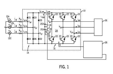
[0013] FIG. 1 a schematic of an AC motor drive according to one aspect of
the
invention.
[0014] FIG. 2 is a schematic view of a fast start-up control scheme for the
motor
drive of FIG. 1 according to an embodiment of the invention.
[0015] FIG. 3 is a detailed schematic view of a current based control
component of
the control scheme of FIG. 2.
[0016] FIG. 4 is a detailed schematic view of a voltage based control
component of
the control scheme of FIG. 2.
[0017] FIG. 5 is a flow chart illustrating a computer implemented technique
for
performing a fast start-up of an induction motor according to an embodiment of
the
invention.
CA 02832747 2013-10-08
WO 2012/142008
PCT/US2012/032841
DETAILED DESCRIPTION OF THE PREFERRED EMBODIMENT
[0018] The
embodiments of the invention set forth herein relate to a system and
method for controlling operation of a motor drive during fast start-up of an
induction
motor. A motor drive is controlled so as achieve a smooth start-up of the
induction
machine without disrupting the operation thereof due to over-current and over-
voltage
trip faults.
[0019]
Embodiments of the invention are directed to AC motor drives encompassing
a plurality of structures and control schemes. The general structure of an AC
motor
drive 10 is shown in FIG. 1. The motor drive 10 may be configured, for
example, as an
adjustable speed drive (ASD) designed to receive a three AC power input,
rectify the
AC input, and perform a DC/AC conversion of the rectified segment into a three-
phase
alternating voltage of variable frequency and amplitude that is supplied to a
load. In a
preferred embodiment, the ASD operates according to an exemplary volts-per-
hertz
characteristic. In this regard, the motor drive provides voltage and output
frequency
regulation in steady state and fast dynamic step load response over a full
load range.
[0020] In an
exemplary embodiment, a three-phase AC input 12a-12c is fed to a
three-phase rectifier bridge 14. The input line impedances are equal in all
three phases.
The rectifier bridge 14 converts the AC power input to a DC power such that a
DC bus
voltage is present between the rectifier bridge 14 and a switch array 16. The
bus voltage
is smoothed by a DC bus capacitor baffl( 18. The switch array 16 is comprised
of a
series of IGBT switches 20 and anti-parallel diodes 22 that collectively form
a PWM
inverter 24. The PWM inverter 24 synthesizes AC voltage waveforms with a fixed
frequency and amplitude for delivery to a load, such as an induction motor 26.
Operation of the inverter 24 is via a control system 28, which may further be
comprised
of a plurality of PI controllers. The control system 28 interfaces to the PWM
inverter
24 via gate drive signals and sensing of the DC bus voltage and pole currents
(by way of
voltage sensor(s) 30 for example) such that changes in DC bus voltage can be
sensed.
These voltage changes can be interpreted as transient load conditions and are
used to
control switching of the switch array 16 of PWM inverter 24 such that near
steady-state
load conditions are maintained.
6
CA 02832747 2013-10-08
WO 2012/142008
PCT/US2012/032841
[0021] In
operation, motor control 10 may be employed to provide a fast start-up of
induction motor 26. In such a fast start-up, the motor control 10 is operated
so as to
cause motor 26 to accelerate up to a desired reference speed. This
acceleration time can
be as fast as 0.1 seconds, for example, from the motor's zero speed to the
desired
reference speed. Responsive to a desired speed input to control system 28,
control
system 28 generates a command signal for controlling a switching time of
switch array
16 in PWM inverter 24 so as to output AC voltage waveforms with a desired
frequency
and amplitude to induction motor 26 that cause the motor to accelerate up to
the desired
reference speed. Included in the command signal are a frequency reference
component
and a voltage reference component that control operation of switch array 16 in
PWM
inverter 24. Control system 28 functions to convert the desired speed to a
frequency
reference component of the command signal. Additionally, control system 28
functions
to multiply the frequency reference by a Volts/Hertz characteristic ratio of
the motor 26
to provide the corresponding voltage reference to the inverter.
[0022]
Referring now to FIG. 2, a control scheme 32 of motor drive 10 is set forth
for implementing a fast-start up of induction motor 26, according to an
embodiment of
the invention. In an exemplary embodiment for the fast start-up scheme 32, the
control
system 28 of motor drive 10 includes a fast start-up modulator 34 that
implements an
algorithm that functions to incrementally adjust the frequency reference of
the command
signal 36 based on a current applied to the induction motor 26 and a DC bus
voltage
present between the rectifier 14 and PWM inverter 24 of motor control 10
(i.e., voltage
on the DC bus 38). In operation, control system 28 initiates the fast start-up
scheme 32
by generating a frequency reference and voltage reference for the command
signal
based on a speed command and acceleration time received from an input device
(not
shown). Upon initiation of the fast start-up of induction motor 26, the three-
phase
current applied to the AC motor and the DC bus voltage are monitored, such as
by way
of current sensors 40 and voltage sensors 30. The measured three-phase current
and DC
bus voltage are received by fast start-up modulator 34, which functions to
process the
received current and voltage values, such as by determining the root mean
square
(RMS) current, I., applied to induction motor 26, for example. The fast start-
up
modulator 34 then subsequently determines what, if any, frequency offsets to
apply to
7
CA 02832747 2013-10-08
WO 2012/142008
PCT/US2012/032841
the frequency reference, fref, of the command signal based on the determined
RMS
current Ir. and DC bus voltage, Vbus, so as to incrementally adjust the
frequency
reference firef of the command signal 36 during the fast start-up operation,
as set forth in
detail below.
[0023] In
operation, fast start-up modulator 34 compares the measured RMS current
Irms to a pre-determined reference current threshold, Ler; set on the
modulator 34.
According to embodiments of the invention, the reference current threshold Lef
can be
set to a value less than or equal to a current value set to cause an over-
current trip fault
in the induction motor 26. In performing the comparison of the measured RMS
current
Irms to the pre-determined reference current threshold Ler; fast start-up
modulator 34
employs a proportional-integral (PI) controller 42, according to one
embodiment of the
invention. As shown in FIG. 2 and in detail in FIG. 3, the PI controller 42
performs the
comparison of the measured RMS current Inns to the pre-determined reference
current
threshold Ler; in order to determine if any adjusting of the process control
inputs to
PWM inverter 24 is needed -- that is if any adjusting of the frequency
reference firef in
the command signal 36 is needed. This adjusting of the frequency reference
fref is
achieved by PI controller 42 by generating a first frequency offset, Afi, that
is applied to
the frequency reference component firef of the command signal.
[0024] In
determining the first frequency offset, Afi, if the PI controller 42
determines that the measured RMS current Inns is less than the pre-determined
reference
current threshold Ira., then the first frequency offset Afi is set by PI
controller 42 to have
a zero value. That is, as the measured RMS current Inns is determined to be at
a level
less than the reference current threshold Ira., it is determined that there is
no danger of an
over-current trip fault occurring and that there is thus no need to adjust the
frequency
reference fref in the command signal output by control system 28 to PWM
inverter 24.
If, however, the PI controller 42 determines that the measured RMS current
Irms is
greater than the pre-determined reference current threshold Iref, then the
first frequency
offset Afi is set by PI controller 42 to have a non-zero value. That is, the
first frequency
offset, Afi, is set to have a value greater than zero (Af1>0). When the first
frequency
offset Afi is set to a value greater than zero, the Afi functions to cause the
frequency
8
CA 02832747 2013-10-08
WO 2012/142008
PCT/US2012/032841
reference of the command signal 36 to be decreased, which in turn modifies the
switching of switching array 16 in PWM inverter 24 to affect the power output
to
induction motor 26. The decreasing of the frequency reference fref of the
command
signal 36 provided by first frequency offset M1 thus serves to reduce the RMS
current
Irms back down to a level equal to or less than the pre-determined reference
current
threshold 'ref in order to prevent an over-current trip fault from occurring.
According to
an exemplary embodiment, the first frequency offset Afi is set to such a level
that the
modified frequency reference of the command signal causes PWM inverter 24 to
generate a power output to induction motor 26 having an RMS current Irms that
is equal
to the pre-determined reference current threshold Iref, such that the output
current
maintains its highest allowable level, while the corresponding torque is used
to
accelerate the induction machine 26 during the fast start-up period.
[0025] As
further shown in FIG. 2, the DC bus voltage Vbus measured by voltage
sensors 30 is provided to fast start-up modulator 34. Fast start-up modulator
34 then
compares the measured DC bus voltage Vbus to a pre-determined reference
voltage
threshold, Vref, set on the modulator 34. According to embodiments of the
invention,
the voltage current threshold Vref can be set to a value less than or equal to
a voltage
value set to cause an over-voltage trip fault in the motor control 10. In
performing the
comparison of the measured DC bus voltage Vbus to the pre-determined reference
voltage threshold Vref, fast start-up modulator 34 employs a transfer function
44 (Gi(s)),
according to one embodiment of the invention. As shown in FIG. 2 and in detail
in FIG.
4, the transfer function 44 compares the measured DC bus voltage Vbus to the
pre-
determined reference voltage threshold Vref, in order to determine if any
adjusting of the
frequency reference fref in the command signal 36 transmitted to PWM inverter
24 is
needed. This adjusting of the frequency reference fref is achieved by transfer
function
44 by generating a second frequency offset, Af2, that is applied to the
frequency
reference firef in the command signal 36.
[0026] In
determining the second frequency offset Af2, if the transfer function 44
determines that the measured DC bus voltage Vbus is less than the pre-
determined
reference voltage threshold Vref, then the second frequency offset Af2 is set
by the
9
CA 02832747 2013-10-08
WO 2012/142008
PCT/US2012/032841
transfer function 44 to have a zero value. That is, as the measured DC bus
voltage Vbus
is determined to be at a level less than the reference voltage threshold Vref,
it is
determined that there is no danger of an over-voltage trip fault occurring and
that there
is thus no need to adjust the frequency reference fref in the command signal
36 output by
control system 28 to PWM inverter 24. If, however, the transfer function 44
determines
that the measured DC bus voltage Vbus is greater than the pre-determined
reference
voltage threshold Vref, then the second frequency offset Af2 is set by
transfer function to
have a non-zero value. That is, the second frequency offset Af2 is set to have
a value
less than zero (Af2<0). When the second frequency offset Af2 is set to a value
less than
zero, the Af2 functions to cause the frequency reference fref of the command
signal 36 to
be increased, which in turn modifies the switching of switching array 16 in
PWM
inverter 24 to affect the power output to induction motor 26.
[0027] The
increasing of the frequency reference fref of the command signal 36
provided by second frequency offset Af2 causes the energy flow from induction
motor
26 back to PWM inverter 24 to decrease, such that the DC bus voltage will be
limited at
a reasonable level. That is, the second frequency offset Af2 is set to such a
level that
upon the induction motor 26 nearing and/or reaching the desired reference
speed, the
synchronous frequency of the frequency reference firef is increased to such a
level that
induction motor 26 is prevented from entering into power generating mode or,
in the
event of the induction machine 26 entering into the power generating mode,
that the
induction motor is changed back into motoring operation mode as soon as
possible.
This in turn reduces the DC bus voltage Vbus back down to a level equal to or
less than
the pre-determined reference voltage threshold Vref in order to prevent an
over-voltage
trip fault from occurring.
[0028] Upon
determination of the first frequency offset M1 and the second frequency
offset Af2, fast start-up modulator 34 is programmed to determine a composite
frequency offset, Afc, that is output from the fast start-up modulator 34,
indicated at
point 46. The composite frequency offset Mc is determined by subtracting Af2
from Afi,
according to:
Af, = Afi - Af2 [Eqn. 1].
CA 02832747 2013-10-08
WO 2012/142008
PCT/US2012/032841
The composite frequency offset Af, thus takes into account any frequency
offsets that
are desired to be made to the frequency reference fref based on both the
measured RMS
current I. and the measured DC bus voltage Vbus.
[0029] Upon
determination of the composite frequency offset Afc, the control system
28 functions to subtract the composite frequency offset Mc from frequency
reference fref
so as to modify a frequency value of the frequency reference (i.e., generate a
modified
frequency reference, fset) in the command signal 36 applied to PWM inverter
24. The
modified frequency reference fset is determined by subtracting Af, from fref,
according to
fset = fref ¨ Afc [Eqn. 2].
Accordingly, in the event that the first frequency offset Afi is greater than
the second
frequency offset Af2, then the modified frequency reference fset will have a
frequency
value that is decreased as compared to the initial frequency reference fref
prior to
application of the composite frequency offset Mc thereto. Conversely, in the
event that
the second frequency offset Af2 is greater than the first frequency offset
Afi, then the
modified frequency reference fset will have a frequency value that is
increased as
compared to the initial frequency reference fref prior to application of the
composite
frequency offset Mc thereto.
[0030] The modified frequency reference fset forms a component of the command
signal generated by control system 28 along with a voltage reference component
of the
command signal 36 that is determined by multiplying the modified frequency
reference
fset by a Volts/Hertz characteristic ratio of the induction motor 26. The
resulting
command signal 36 generated by control system 28, including the modified
frequency
reference fset and the voltage reference, determines a particular space vector
modulation
(SVM) control scheme that is provided to PWM inverter 24 for controlling the
switching time of switch array 16. Accordingly, AC voltage waveforms with a
desired
frequency and amplitude are output to induction motor 26 that cause the motor
to
accelerate up to the desired reference speed, while maintaining the RMS
current Irms and
the DC bus voltage Vbus below the identified over-current trip fault set-point
and over-
voltage trip fault set-point.
11
CA 02832747 2013-10-08
WO 2012/142008
PCT/US2012/032841
[0031] In
operation, the fast start-up modulator 34 is programmed to incrementally
adjust/update a value of the composite frequency offset Af, output therefrom
during the
course of the fast start-up period of induction motor 26. The RMS current Irms
and the
DC bus voltage Vbus are monitored throughout the fast start-up period of
operation, such
that any changes in the RMS current I. and/or the DC bus voltage Vbus are
reflected in
updated values for the first frequency offset Aft and the second frequency
offset Af2,
(and the resulting composite frequency offset Mc) output by the fast start-up
modulator
34 for altering the frequency reference fref component of the command signal
to a
desired modified frequency reference fset.
[0032] It is
recognized that additional elements can be provided for control scheme
32 to provide for a smooth fast start-up process. For example, as shown in
FIG. 2, fast
start-up modulator 34 can also includes a high-pass filter 48 (G2(s)) that
generates an
offset, Af3, that is applied to the command signal 36 generated by control
system 28.
The application of the offset, Af3, in conjunction with the application of the
composite
frequency offset Afe, provides for a smooth, fast start-up process of
induction motor 26.
[0033]
Referring now to FIG. 5, and with continued reference to FIG. 2, a computer
implemented technique 50 for controlling operation of motor drive 10 during
fast start-
up of induction motor 26 is set forth. The technique can, for example, be
implemented
via an algorithm performed by fast start-up modulator 34 of control system 28.
The
technique 50 begins at STEP 52 where a start command for the induction motor
26 is
received. Associated with the start command is a generation of a command
signal 36
having a frequency reference component and voltage reference component
therein, with
the particulars of the command signal being based on a user input of a desired
speed at
which the motor 26 is to be operated. An initial determination is then made at
STEP 52
as to whether the motor is currently accelerating. If the motor is determined
to be
accelerating 56, then technique continues at STEP 58 by measuring and/or
determining
current and voltage parameters of the motor drive 10 that are resultant from
the input of
the particular command signal 36 to the PWM inverter 24 therein. That is, the
root
mean square (RMS) of the three-phase current applied to the induction motor,
Irms, and
the DC bus voltage of the motor drive, Vbus, are determined.
12
CA 02832747 2013-10-08
WO 2012/142008
PCT/US2012/032841
[0034] In next STEPS 60, 62 of technique 50, the RMS current Ir. and DC bus
voltage Vbus are received by fast start-up modulator 34 of control system 28
and are
compared to a pre-determined reference current threshold, Ira., and a pre-
determined
reference voltage threshold, Vref, respectively. According to embodiments of
the
invention, the reference current threshold 'ref can be set to a value less
than or equal to a
current value set to cause an over-current trip fault in the induction motor
26 and the
reference voltage threshold Vref can be set to a value less than or equal to a
voltage
value set to cause an over-voltage trip fault in the motor control.
[0035] A determination is made at STEP 64 as to whether the measured RMS
current
Irms exceeds a pre-determined reference current threshold Iref, in order to
determine if
any adjusting of the process control inputs to PWM inverter 24 is needed --
that is, if
any adjusting of the frequency reference fref in the command signal 36 is
needed based
on the measured current. According to an exemplary embodiment of the
invention, in
performing the comparison of the measured RMS current Irms to the pre-
determined
reference current threshold Iref, fast start-up modulator 34 employs a
proportional-
integral (PI) controller 42. If it is determined that the measured RMS current
Irms
exceeds the pre-determined reference current threshold Iref 66, then the fast
start-up
modulator 34 functions to generate a first frequency offset, Afi, at STEP 68
to be
applied to the frequency reference fref in the command signal 36 to provide
for
adjustment of the frequency reference. Alternatively, if it is determined that
the
measured RMS current Irms does not exceed the pre-determined reference current
threshold Iref 70, then the technique 50 determines that no adjustment of the
frequency
reference fref is needed. In the embodiment of technique 50 illustrated in
FIG. 5, the
technique 50 would thus continue by bypassing STEP 68. According to another
embodiment of the invention, the technique 50 could also set a first frequency
offset Afi
generated by fast start-up modulator 34 to zero (i.e., a zero offset), such
that no
adjustment/offset is applied to the frequency reference fref.
[0036]
Concurrently with the determination made at STEP 64 as to whether the
measured RMS current Irms exceeds the pre-determined reference current
threshold 'ref,
the technique also determines at STEP 72 whether the measured DC bus voltage
Vb.
13
CA 02832747 2013-10-08
WO 2012/142008
PCT/US2012/032841
exceeds the pre-determined reference voltage threshold Vref, in order to
determine if any
adjusting of the process control inputs to PWM inverter 24 is needed -- that
is, if any
adjusting of the frequency reference fref in the command signal 36 is needed
based on
the measured voltage. According to an exemplary embodiment of the invention,
in
performing the comparison of the measured DC bus voltage Vbus to the pre-
determined
reference voltage threshold Vref, fast start-up modulator 34 employs a
transfer function
(Gi(s)) 44. If it is determined that the measured DC bus voltage Vbus exceeds
the pre-
determined reference voltage threshold Vref 74, then the fast start-up
modulator 34
functions to generate a second frequency offset, Af2, at STEP 76 to be applied
to the
frequency reference fref in the command signal 36 to provide for adjustment of
the
frequency reference. Alternatively, if it is determined that the measured DC
bus voltage
Vbus does not exceed the pre-determined reference voltage threshold Vref 78,
then the
technique 50 determines that no adjustment of the frequency reference fref is
needed. In
the embodiment of technique 50 illustrated in FIG. 5, the technique 50 would
thus
continue by bypassing STEP 76. According to another embodiment of the
invention,
the technique 50 could also set a second frequency offset Af2 generated by
fast start-up
modulator 34 to zero (i.e., a zero offset), such that no adjustment/offset is
applied to the
frequency reference fref.
[0037]
Referring still to FIG. 5, upon determination of any first frequency offset
Afi
and the second frequency offset Af2 at STEPS 68, 76, technique 50 continues at
STEP
80 where fast start-up modulator 34 determines a composite frequency offset,
Afe, that is
to be output therefrom. The composite frequency offset Af, is determined by
subtracting Af2 from Afi, and thus the composite frequency offset Af, takes
into account
any frequency offsets that are desired to be made to the frequency reference
fref based on
both the measured RMS current Irms and the measured DC bus voltage Vbus=
[0038] Upon
determination of the composite frequency offset Afe, technique 50
continues at STEP 82, where the composite frequency offset Af, is applied to,
and
subtracted from, the frequency reference fref so as to modify a frequency
value of the
frequency reference (i.e., generate a modified frequency reference, fset) in
the command
signal 36 applied to the PWM inverter 24. Accordingly, in the event that the
first
14
CA 02832747 2013-10-08
WO 2012/142008
PCT/US2012/032841
frequency offset Afi is greater than the second frequency offset Af2, then the
modified
frequency reference fset will have a frequency value that is decreased as
compared to the
initial frequency reference fref prior to application of the composite
frequency offset Mc
thereto. Conversely, in the event that the second frequency offset Af2 is
greater than the
first frequency offset Afi, then the modified frequency reference fset will
have a
frequency value that is increased as compared to the initial frequency
reference fref prior
to application of the composite frequency offset Mc thereto.
[0039] As shown
in FIG. 5, upon application of the composite frequency offset Af,
to the frequency reference fref to generate a modified frequency reference,
fset, technique
50 continues by looping back to STEP 54, where a determination is again made
as to
whether the motor is currently accelerating. If the motor is determined to
still be
accelerating 56, the technique 50 then proceeds through another iteration of
determining/generating an appropriate composite frequency offset Af, to apply
to the
frequency reference fref that will result in the PWM inverter generating an
output power
that maintains the RMS current I. and the DC bus voltage Vbus below the
identified
over-current trip fault set.
Technique 50 thus provides for incremental
adjusting/updating of the value of the composite frequency offset Af, output
therefrom
during the course of the fast start-up period of induction motor 26.
[0040] In
running through each iteration of technique 50, if it is determined at STEP
54 that the motor is not accelerating 84, then technique continues at STEP 86
where the
first frequency offset Afi and the second frequency offset Af2 are set to zero
(i.e., zero
offset). The technique 50 then continues at STEPS 80, 82 where the composite
frequency offset Af, would thus be zero and the modified frequency reference
fset would
be unchanged from the frequency reference fref.
[0041] Thus,
according to embodiments of the invention, a control scheme and
technique are provided for controlling operation of a motor drive during fast
start-up of
an induction motor. The RMS current I. applied to the induction motor and the
DC
bus voltage Vbus present on the DC bus of the motor control are monitored
while the
motor is accelerating during the fast start-up. A frequency offset is
incrementally
applied to the frequency reference component of the command signal generated
by the
CA 02832747 2013-10-08
WO 2012/142008
PCT/US2012/032841
control signal of the motor drive based on the RMS current I. and the DC bus
voltage
Vbus values, with the PWM inverter of the motor drive generating an output
power
responsive to the command signal containing the modified reference frequency
component. The presence of the modified reference frequency component in the
command signal causes the RMS current I. and the DC bus voltage Vbus present
in the
motor drive to be maintained below identified over-current and over-voltage
trip fault
settings, such that a smooth start-up of the induction machine is provided.
[0042] A
technical contribution for the disclosed method and apparatus is that it
provides for a computer implemented technique for controlling operation of a
motor
drive during fast start-up of an induction motor. The technique incrementally
adjusts a
value of a frequency offset applied to a reference frequency component of a
command
signal during the course of the fast start-up period of the induction motor,
such that a
motor current output by the motor drive and a DC bus voltage present in the
motor drive
are maintained below identified over-current and over-voltage trip fault
settings and so
as to ensure a smooth start-up of the induction motor.
[0043]
Therefore, according to one embodiment of the present invention, a system to
control operation of an AC motor includes an AC motor drive having an input
connectable to an AC source and an output connectable to an input terminal of
an AC
motor, with the AC motor drive further including a rectifier connected to the
input, a
pulse width modulation (PWM) inverter connected to the rectifier by way of a
DC bus
and having a plurality of switches therein to control current flow and
terminal voltages
in the AC motor, and a control system connected to the PWM inverter being
configured
to generate a command signal to cause the PWM inverter to control an output of
the AC
motor drive corresponding to the input to the AC motor, with the command
signal
including a frequency reference and a voltage reference. The control system
includes a
start-up modulator that is selectively operable during a start-up acceleration
of the AC
motor to a desired reference speed, with the start-up modulator being
programmed to
determine each of a motor current applied to the AC motor and a voltage of the
DC bus,
generate a first frequency offset that causes the frequency reference of the
command
signal to be decreased when the motor current is greater than a reference
current
16
CA 02832747 2013-10-08
WO 2012/142008
PCT/US2012/032841
threshold, and generate a second frequency offset that causes the frequency
reference of
the command signal to be increased when the DC bus voltage is greater than a
reference
voltage threshold.
[0044]
According to another embodiment of present invention, a method for
controlling operation of an AC motor during acceleration of the AC motor in a
start-up
mode of operation by way of a motor drive includes the step of generating a
command
signal in a control system of the motor drive based on a desired speed of the
AC motor,
the command signal including a frequency reference and a voltage reference.
The
method also includes the steps of transmitting the command signal to a pulse
width
modulation (PWM) inverter of the motor drive to control an output of the PWM
inverter
so as to thereby control current flow and terminal voltages in the AC motor
and
incrementally adjusting the command signal transmitted to the PWM inverter
during the
start-up mode of operation based on a motor current applied to the AC motor
and a
voltage an a DC bus of the motor drive. The step of incrementally adjusting
the
command signal further includes determining each of the motor current applied
to the
AC motor and the DC bus voltage, comparing the motor current to a reference
current
threshold and the DC bus voltage to a reference voltage threshold,
respectively,
decreasing the frequency reference in the command signal if the motor current
is greater
than the reference current threshold, and increasing the frequency reference
in the
command signal if the DC bus voltage is greater than the reference voltage
threshold.
[0045] According to yet another embodiment of the present invention, an AC
motor
drive to control transmission of voltage and current from an AC power source
to an AC
motor includes an input and an output connectable to an AC source and to an
input
terminal of the AC motor, respectively, a rectifier connected to the input,
and a pulse
width modulation (PWM) inverter connected to the rectifier by way of a DC bus
and
having a plurality of switches therein to control current flow and terminal
voltages in
the AC motor. The AC motor drive also includes a control system connected to
the
PWM inverter and configured to determine each of a root mean square (RMS)
current
applied to the AC motor and a voltage of the DC bus and compare the RMS
current and
the DC bus voltage to a reference current threshold and a reference voltage
threshold,
17
CA 02832747 2013-10-08
WO 2012/142008
PCT/US2012/032841
respectively. The control system is further configured to determine a first
frequency
offset based on the comparison of the RMS current value to the reference
current
threshold, determine a second frequency offset based on the comparison of the
DC bus
voltage to the reference voltage threshold, combine the first frequency offset
and the
second frequency offset to determine a composite frequency offset, and
generate a
modified frequency reference in the command signal based on the composite
frequency
offset.
[0046] The
present invention has been described in terms of the preferred
embodiment, and it is recognized that equivalents, alternatives, and
modifications, aside
from those expressly stated, are possible and within the scope of the
appending claims.
18