Note: Descriptions are shown in the official language in which they were submitted.
CA 02832815 2013-10-09
WO 2012/141914 PCT/US2012/031256
ULTRASOUND GUIDED POSITIONING OF
CARDIAC REPLACEMENT VALVES WITH 3D VISUALIZATION
CROSS REFERENCE TO RELATED APPLICATIONS
[0001] This Application claims priority to US Provisional Application
61/474,028,
filed April 11, 2011, US Provisional Application 61/565,766, filed December 1,
2011, and
US Application 13/410,456, filed March 2, 2012, each of which is incorporated
herein by
reference.
BACKGROUND
[0002] Conventional percutaneous cardiac valve replacement procedure
relies on
Trans-Esophageal Echocardiography (TEE) in combination with Fluoroscopy for
guiding the
valve into position where it is to be deployed. It is easy to see the tissue
and the anatomical
landmarks on the ultrasound image, but difficult to visualize the valve and
its deployment
catheter. Conversely, it is easy to see the valve and catheter on the
fluoroscopy image, but
difficult to clearly see and differentiate the tissue. Since neither imaging
modality provides a
clear view of both the anatomy and the valve, it difficult to determine
exactly where the valve
is with respect to the relevant anatomy. This makes positioning of the
artificial valve prior to
deployment quite challenging.
[0003] Relevant background material also includes US patents 4,173,228,
4,431,005,
5,042,486, 5,558,091, and 7,806,829, each of which is incorporated herein by
reference.
SUMMARY OF THE INVENTION
[0004] One aspect of the invention is directed to a method of visualizing
a device in a
patient's body using an ultrasound probe and a device installation apparatus.
The ultrasound
probe includes an ultrasound transducer that captures images of an imaging
plane and a first
1
CA 02832815 2013-10-09
WO 2012/141914 PCT/US2012/031256
position sensor mounted so that a geometric relationship between the first
position sensor and
the ultrasound transducer is known. The device installation apparatus includes
the device
itself, a device deployment mechanism, and a second position sensor mounted so
that a
geometric relationship between the second position sensor and the device is
known. This
method includes the steps of detecting a position of the first position
sensor, detecting a
position of the second position sensor, and determining a spatial relationship
in three-
dimensional space between the device and the imaging plane based on (a) the
detected
position of the first position sensor and the geometric relationship between
the first position
sensor and the ultrasound transducer and (b) the detected position of the
second position
sensor and the geometric relationship between the second position sensor and
the device. A
representation of the device and the imaging plane, as viewed from a first
perspective, are
displayed, so that a spatial relationship between the representation of the
device and the
representation of the imaging plane corresponds to the determined spatial
relationship. A
representation of the device and the imaging plane, as viewed from a second
perspective, is
also displayed, so that a spatial relationship between the representation of
the device and the
representation of the imaging plane corresponds to the determined spatial
relationship. In
some embodiments, the second perspective is displayed after the first
perspective. The
transition from the first perspective to the second perspective can occur in
response to a
command received via a user interface. Optionally, a wireframe rectangular
parallelepiped
(e.g., a cube) with two faces that are parallel to the imaging plane may also
be displayed.
Optionally, additional perspectives may also be displayed.
[0005] Another aspect of the invention is directed to an apparatus for
visualizing a
position of a device in a patient's body using an ultrasound probe and a
device installation
apparatus. The ultrasound probe includes an ultrasound transducer that
captures images of an
imaging plane and a first position sensor mounted so that a geometric
relationship between
2
CA 02832815 2013-10-09
WO 2012/141914 PCT/US2012/031256
the first position sensor and the ultrasound transducer is known. The device
installation
apparatus including the device itself, a device deployment mechanism, and a
second position
sensor mounted so that a geometric relationship between the second position
sensor and the
device is known. This apparatus includes an ultrasound imaging machine that
drives the
ultrasound transducer, receives return signals from the ultrasound transducer,
converts the
received return signals into 2D images of the imaging plane, and displays the
2D images. It
also includes a position tracking system that detects a position of the first
position sensor,
detects a position of the second position sensor, reports the position of the
first position
sensor to the ultrasound imaging machine, and reports the position of the
second position
sensor to the ultrasound imaging machine. The ultrasound imaging machine
includes a
processor that is programmed to determine a spatial relationship in three-
dimensional space
between the device and the imaging plane based on (a) the detected position of
the first
position sensor and the geometric relationship between the first position
sensor and the
ultrasound transducer and (b) the detected position of the second position
sensor and the
geometric relationship between the second position sensor and the device. The
processor is
programmed to generate a first representation of the device and a first
representation of the
imaging plane, as viewed from a first perspective, so that a spatial
relationship between the
first representation of the device and the first representation of the imaging
plane corresponds
to the determined spatial relationship. It is also programmed to generate a
second
representation of the device and a second representation of the imaging plane,
as viewed from
a second perspective, so that a spatial relationship between the second
representation of the
device and the second representation of the imaging plane corresponds to the
determined
spatial relationship. The ultrasound imaging machine displays the first
representation of the
device and the first representation of the imaging plane, and displays the
second
representation of the device and the second representation of the imaging
plane. In some
3
CA 02832815 2013-10-09
WO 2012/141914 PCT/US2012/031256
embodiments, the second representation of the device and the second
representation of the
imaging plane are displayed after the first representation of the device and
the first
representation of the imaging plane. In some embodiments, the apparatus may
further
include a user interface, and a transition from displaying the first
representation of the device
and the imaging plane to displaying the second representation of the device
and the imaging
plane may occur in response to a command received via the user interface.
Optionally,
additional perspectives may be added, and/or a wireframe rectangular
parallelepiped with two
faces that are parallel to the imaging plane may be displayed together with
the device and the
imaging plane in each of the different perspectives.
BRIEF DESCRIPTION OF THE DRAWINGS
[0006] FIG. 1 depicts the distal end of an ultrasound probe that
includes, in addition
to conventional components, a first position sensor.
[0007] FIG. 2 depicts the distal end of a valve installation apparatus
includes, in
addition to conventional components, a second position sensor.
[0008] FIG. 3 is a block diagram of a system that makes use of the
position sensors to
track the position of the valve so that it can be installed at the correct
anatomical position.
[0009] FIG. 4 depicts the geometric relationship between the ultrasound
transducer,
the transducer's imaging plane, and two position sensors.
[0010] FIG. 5A depicts a wireframe 3D cube that is constructed about a 2D
imaging
plane, with a representation of the position of the valve when the valve is at
a first position.
[0011] FIG. 5B depicts the wireframe 3D cube and the 2D imaging plane of
FIG. 5A,
with a representation of the position of the valve when the valve is at a
second position.
4
CA 02832815 2013-10-09
WO 2012/141914 PCT/US2012/031256
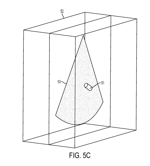
[0012] FIG. 5C depicts the wireframe 3D cube and the 2D imaging plane of
FIG. 5B
after being spun to a different perspective.
[0013] FIG. 5D depicts the wireframe 3D cube and the 2D imaging plane of
FIG. 5B
after being tipped to a different perspective.
[0014] FIG. 6A depicts an imaging plane at a particular orientation in
space.
[0015] FIG. 6B depicts how the orientation of a displayed imaging plane
is set to
match the orientation of the imaging plane in FIG. 6A.
DESCRIPTION OF THE PREFERRED EMBODIMENTS
[0016] FIGS. 1-4 depict one embodiment of the invention in which the
position of the
valve may be visualized easily on the ultrasound image so as to make the
deployment of the
valve much easier due to a much more confident assessment of its position. In
this
embodiment, position sensors are added to a conventional ultrasound probe and
to a
conventional valve delivery apparatus, and data from those position sensors is
used to
determine the location of valve with respect to the relevant anatomy.
[0017] FIG. 1 depicts the distal end of an ultrasound probe 10. In most
respects, the
ultrasound probe 10 is conventional ¨ it has a housing 11 and an ultrasound
transducer 12
located within the distal end of the probe 10 and a flexible shaft (not
shown). However, in
addition to the conventional components, a position sensor 15 is added,
together with
associated wiring to interface with the position sensor 15. The position
sensor 15 can be
located anywhere on the distal end of the probe 10, as long as the geometric
relationship
between the position sensor 15 and the ultrasound transducer 12 is known.
Preferably, that
relationship is permanently fixed by mounting the ultrasound transducer 12 and
the position
sensor 15 so that neither can move with respect to the housing 11. Appropriate
wiring to the
CA 02832815 2013-10-09
WO 2012/141914 PCT/US2012/031256
position sensor 15 is provided, which preferably terminates at an appropriate
connector (not
shown) on the proximal end of the probe. Of course, in alternative embodiments
that use a
wireless position sensor, the wiring is not necessary.
[0018] In the illustrated embodiment, the position sensor is located on
the proximal
side of the ultrasound transducer 12 by a distance dl measured from the center
of the
ultrasound transducer 12 to the center of the position sensor 15. In
alternative embodiments,
the position sensor 15 can be placed in other locations, such as distally
beyond the ultrasound
transducer 12, laterally off to the side of the ultrasound transducer 12, or
behind the
transducer 12. In embodiments that place the position sensor 15 behind the
transducer,
smaller sensors are preferred to prevent the overall diameter of the
ultrasound probe 10 from
getting too large.
[0019] FIG. 2 depicts the distal end of a valve installation apparatus 20
which is used
to deliver a valve 23 to a desired position with respect to a patient's
anatomy and then deploy
the valve 23 at that position. In most respects, construction of the valve
installation apparatus
20 is conventional. A conventional valve 23 is mounted on a conventional
deployment
mechanism 22 in a conventional manner and delivered through delivery sheath
24, so that
once the valve is positioned at the correct location, actuation of the
deployment mechanism
22 installs the valve. Examples of suitable valves and valve installation
apparatuses include
the Sapien Valve System by Edwards Lifesciences, the CoreValve System by
Medtronic, and
the valve by Direct Flow Medical.
[0020] However, in addition to the conventional components described
above, a
position sensor 25 is added, together with associated wiring to interface with
the position
sensor 25.
6
CA 02832815 2013-10-09
WO 2012/141914 PCT/US2012/031256
[0021] The position sensor 25 is located in a position on the valve
installation
apparatus 20 that has a known geometric relationship with the valve 23. For
example, as
shown in FIG. 2, the position sensor 25 can be located on the delivery
catheter, at a distance
d2 distally or proximal beyond a known position of the valve 23 (measured when
the valve is
in its undeployed state). Preferably, the valve installation apparatus 20 is
constructed so that
the spatial relationship will not change until deployment is initiated (e.g.,
by inflating a
balloon). Mechanically adding the position sensor 25 to the valve installation
apparatus 20
will depend on the design of the valve installation apparatus 20, and
appropriate wiring to the
position sensor 25 must be provided, which preferably terminates at an
appropriate connector
(not shown) on the proximal end of the valve installation apparatus 20. Of
course, in
alternative embodiments that use a wireless position sensor, the wiring is not
necessary.
[0022] In alternative embodiments, the position sensor 25 can be placed
in other
locations, such as on the deployment mechanism 22 or on the delivery sheath
24. In still
other alternative embodiments, the position sensor 25 could be positioned on
the valve 23
itself (preferably in a way that the position sensor 25 is released when the
valve is deployed).
However, the position sensor 25 must be positioned so that its relative
position with respect
to the valve 23 is known (e.g., by placing it at a fixed position with respect
to the valve 23).
When this is done, it becomes possible to determine the position of the valve
23 by adding an
appropriate offset in three dimensional space to the sensed position of the
sensor 25.
[0023] Commercially available position sensors may be used for the
position sensors
15, 25. One example of a suitable sensor is the "model 90" by Ascension
Technologies,
which are small enough (0.9mm in diameter) to be integrated into the distal
end of the probe
and the valve installation apparatus 20. These devices have previously been
used for
purposes including cardiac electrophysiology mapping and needle biopsy
positioning, and
7
CA 02832815 2013-10-09
WO 2012/141914 PCT/US2012/031256
they provide six degrees of freedom information (X, Y, and Z Cartesian
coordinates) and
orientation (azimuth, elevation, and roll) with a high degree of positional
accuracy.
[0024] Other examples include the sensors made using the technology used
by
Polhemus Inc. The various commercially available systems differ in the way
that they create
their signal and perform their signal processing, but at long as they are
small enough to fit
into the distal end of an ultrasound probe 10 and the valve installation
apparatus 20, and can
output the appropriate position and orientation information, any technology
may be used
(e.g., magnetic-based technologies and RF-based systems).
[0025] FIG. 3 is a block diagram of a system that makes use of the
position sensors
15, 25 to track the position of the valve so that it can be installed at the
correct anatomical
position. In this system, ultrasound images obtained using the transducer 12
at the distal end
of the probe 10 are combined with information obtained by tracking the
position sensor 15 on
the distal end of an ultrasound probe 10 and the position sensor 25 on the
valve installation
apparatus 20, to position the valve at a desired spot within the patient's
body before
deployment.
[0026] In FIG. 3, the valve installation apparatus 20 is schematically
depicted as
being inside the heart of the patient. Access to the heart may be achieved
using a
conventional procedure (e.g., via a blood vessel like an artery). In addition,
FIG. 3, the distal
end of the ultrasound probe 10 is shown as being next to the heart. Access to
this location is
preferably accomplished by positioning the distal end of the probe 10 in the
patient's
esophagus, (e.g., via the patient's mouth or nose).
[0027] The ultrasound imaging machine 30 interacts with the transducer in
the distal
of the probe 10 to obtain 2D images in a conventional matter (i.e., by driving
the ultrasound
transducer, receiving return signals from the ultrasound transducer,
converting the received
8
CA 02832815 2013-10-09
WO 2012/141914 PCT/US2012/031256
return signals into 2D images of the imaging plane, and displaying the 2D
images). But in
addition to the conventional connection between the ultrasound imaging machine
30 and the
transducer in the distal end of the probe 10, there is also wiring between the
position tracking
system 35 and the position sensor 15 at the distal end of the ultrasound
probe. In the
embodiment that uses Ascension model 90 position sensors, an Ascension 3D
Guidance
MedsafeTM electronics unit may be used as the position tracking system 35.
Since the wiring
between the position tracking system 35 and the position sensor is built into
the model 90
sensor, the model 90 sensor may be integrated into the distal end of an
ultrasound probe 10 in
a way that permits the connector at the proximal end of the model 90 sensor to
branch over to
the position tracking system 35. In alternative embodiments, the proximal end
of the
ultrasound probe 10 may be modified so that a single connector that terminates
at the
ultrasound imaging machine 30 can be used, with appropriate wiring added to
route the
signals from the position sensor 15 to the position tracking system 35.
[0028] A similar position sensor 25 is also disposed at the distal end of
the valve
installation apparatus 20. A connection between the position sensor 25 and the
position
tracking system 35 is providing by appropriate wiring that runs from the
distal end of the
apparatus through the entire length of apparatus and out of the patient's
body, and from there
to the position tracking system 35. Suitable ways for making the electrical
connection
between the position tracking system 35 and the position sensor 25 will be
apparent to person
skilled in the relevant arts. Note that since the distal end of the valve
installation apparatus
20 is positioned in the patient's heart during deployment, the wiring must fit
within the
catheter that delivers the valve installation apparatus 20 to that position,
which is typically
positioned in the patient's arteries.
9
CA 02832815 2013-10-09
WO 2012/141914 PCT/US2012/031256
[0029] With this arrangement, the position tracking system 35 can
determine the
exact position and orientation in three-dimensional space of the position
sensor 15 at the
distal end of the ultrasound probe and of the position sensor 25 at the distal
end of the valve
installation apparatus 20. The position tracking system 35 accomplishes this
by
communicating with the position sensors 15, 25 via the transmitter 36 which is
positioned
outside the patient's body, preferably in the vicinity of the patient's heart.
This tracking
functionality is provided by the manufacturer of the position tracking system
35, and it
provides an output to report the position and orientation of the sensors.
[0030] A processor (not shown) uses the hardware depicted in FIG. 3 to
help guide
the valve installation apparatus 20 to a desired position. This processor can
be implemented
in a stand-alone box, or can be implemented as a separate processor that is
housed inside the
ultrasound imaging machine 30. In alternative embodiments, an existing
processor in the
ultrasound imaging machine 30 may be programmed to perform the program steps
described
herein. But wherever the processor is located, when the distal end of the
ultrasound probe 10
is positioned near the patient's heart (e.g., in the patient's esophagus or in
the fundus of the
patient's stomach), and the distal end of the valve installation apparatus 20
is positioned in
the patient's heart in the general vicinity of its target destination, the
system depicted in FIG.
3 can be used to accurately position the valve 23 at a desired location by
performing the steps
described below.
[0031] Referring now to FIGS. 1-4, taken together, the position tracking
system 35
first reports the location and orientation of the position sensor 15 to the
processor. That
position is depicted as point 42 in FIG. 4. Because of the fixed geometric
relationship
between the position sensor 15 and the ultrasound transducer 12, and the known
relationship
between the ultrasound transducer 12 and the imaging plane 43 of that
transducer, the
CA 02832815 2013-10-09
WO 2012/141914 PCT/US2012/031256
processor can determine the location of the imaging plane 43 (referred to
herein as the XY
plane) in space based on the sensed position and orientation of the position
sensor 15.
[0032] The position tracking system 35 also determines the position of
the position
sensor 25 at the distal end of the valve installation apparatus 20. That
position is depicted as
point 45 in FIG. 4. Then, based on the known location of point 45 and the
known location of
the XY plane 43 (which was calculated from the measured position 42 and the
known offset
between point 42 and the ultrasound transducer 12), the processor computes a
projection of
point 45 onto the XY plane 43 and the distance Z between point 45 and the XY
plane. This
projection is labeled 46 in FIG. 4.
[0033] The processor then sends the signed value of Z and the coordinates
of point 46
to the software object in the ultrasound imaging machine 30 that is
responsible for generating
the images that are ultimately displayed. That software object is modified
with respect to
conventional ultrasound imaging software so as to display the location of
point 46 on the
ultrasound image. This can be accomplished, for example, by displaying a
colored dot at the
position of point 46 on the XY plane 43. The modifications that are needed to
add a colored
dot to an image generated by a software object will be readily apparent to
persons skilled in
the relevant arts.
[0034] Preferably, the distance Z is also displayed by the ultrasound
imaging machine
30. This can be accomplished using any of a variety of user interface
techniques, including
but not limited to displaying a numeric indicator of the value of Z to specify
the distance in
front of or behind the XY imaging plane 43, or displaying a bar graph whose
length is
proportional to the distance Z and whose direction denotes the sign of Z. In
alternative
embodiments other user interface techniques may be used, such as relying on
color and/or
intensity to convey the sign and magnitude of Z to the operator. The
modifications that are
11
CA 02832815 2013-10-09
WO 2012/141914 PCT/US2012/031256
needed to add this Z information to the ultrasound display will also be
readily apparent to
persons skilled in the relevant arts.
[0035] When the system is configured in this way, during use the operator
will be
able to see the relevant anatomy by looking at the image that is generated by
the ultrasound
imaging machine 30. Based on the position of the dot representing point 46
that was
superposed on the imaging plane, and the indication of the value of Z, the
operator can
determine where the position sensor 25 is with respect to the portion of the
patient's anatomy
that appears on the display of the ultrasound imaging machine 30.
[0036] Based on the known geometric offset between the position sensor 25
and the
valve 23, the operator can use the image displayed by the ultrasound imaging
machine 30, the
position point 46 that is superposed on that image, and the display of Z
information to
position the valve at the appropriate anatomical location.
[0037] In alternative preferred embodiments, instead of having the
operator account
for the offset between the position sensor 25 and the valve 23, the system is
programmed to
automatically offset the displayed value of the Z by the distance d2, which
eliminates the
need for the operator to account for that offset himself In these embodiments,
the procedure
of valve deployment becomes very simple. The valve installation apparatus 20
is snaked
along the blood vessel until it is in the general vicinity of the desired
position. Then, the
operator aligns the imaging plane with the a cross sectional view of the
desired position
within the patients original valve that is being treated by, for example,
advancing or retracting
the distal end of an ultrasound probe 10, and/or flexing a bending section of
that probe. An
indication that the proper position has been reached is when (a) the imaging
plane displayed
on the ultrasound imaging machine 30 depicts the desired position within the
patients original
valve, (b) the position marker 46 that is superposed on the ultrasound image
indicates that the
12
CA 02832815 2013-10-09
WO 2012/141914 PCT/US2012/031256
valve is aligned within the desired position of the valve, and (c) the Z
display indicates that
Z = O. After this, the deployment mechanism 22 can be triggered (e.g., by
inflating a
balloon), which deploys the valve.
[0038] In the above-described embodiments, the information is presented
to the user
in the form of a conventional 2D ultrasound image with (1) a position marker
added to the
image plane to indicate a projection of the valve's location onto the image
plane and (2) and
indication of the distance between the valve and the image plane. In
alternative
embodiments, different ways to help the user visualize the position of the
valve with respect
to the relevant anatomy may be used.
[0039] One such approach is to make a computer-generated model of an
object in 3D
space, in which the object incorporates both the valve and the 2D imaging
plane that is
currently being imaged by the ultrasound system. Using a suitable user
interface, the user
can then view the object from different perspectives using 3D image
manipulation techniques
that are commonly used in the context of computer aided design (CAD) systems
and gaming
systems. A suitable user interface, which can be implemented using any of a
variety of
techniques used in conventional CAD and gaming systems, then enables the user
to view the
object from different perspectives (e.g., by rotating the object about
horizontal and/or vertical
axes).
[0040] FIG. 5A depicts such an object in 3D space, and the object has
three
components: a wireframe 3D cube 52, the 2D imaging plane 53 that is currently
being imaged
by the ultrasound system, and a cylinder 51 that represents the position of
the position sensor
25 (shown in FIG. 2). The starting frame of reference for creating the object
is the imaging
plane 53, whose position in space (with respect to the ultrasound transducer)
is known based
on the fixed geometric relationship between the ultrasound transducer 12 and
the position
13
CA 02832815 2013-10-09
WO 2012/141914 PCT/US2012/031256
sensor 15 (both shown in FIG. 2), and the detected position of the position
sensor, as
described above. The system then adds the wire frame cube 52 at a location in
space that
positions both the front and rear faces of the wire frame cube 52 parallel to
the imaging plane
53, preferably with the imaging plane 53 at the median plane of the 3D cube.
The system
also adds the cylinder 51 to the object at an appropriate location that
corresponds to the
detected position of position sensor 25 (shown in FIG. 2). Preferably, the
spatial relationship
in three-dimensional space between the cylinder and the imaging plane is
determined based
on (a) the detected position of the first position sensor and the geometric
relationship between
the first position sensor and the ultrasound transducer and (b) the detected
position of the
second position sensor and the geometric relationship between the second
position sensor and
the device, as explained above. In alternative embodiments, the cube may be
omitted, and in
other embodiments, a rectangular parallelepiped or another geometric shape may
be used
instead of a cube.
[0041] Since the valve is in a fixed geometric relationship with the
position sensor 25,
moving the valve to a new position is detected by the system, and the system
responds to the
detected movement by moving the cylinder 51 to a new position within the 3D
object, as
shown in FIG. 5B. Preferably, the object can be rotated by the user to help
the user better
visualize the location of the position sensor 25 in 3D space. Assume, for
example, that the
position sensor 25 remains at the location that caused the system to paint the
cylinder 51 at
the location shown in FIG. 5B, as viewed from a first perspective. Initially,
the display that is
presented to the user includes a first representation of the device and a
first representation of
the imaging plane, as viewed from the first perspective, so that a spatial
relationship between
the first representation of the device and the first representation of the
imaging plane
corresponds to the spatial relationship determined based on measurements from
the position
sensors and subsequent computations.
14
CA 02832815 2013-10-09
WO 2012/141914 PCT/US2012/031256
[0042] If the user wants to view the geometry from a different
perspective, he can use
the user interface to spin the perspective to a second view shown in FIG. 5C,
or to tip the
perspective to a third view shown in FIG. 5D. The second and third views both
include
representations of the device and the imaging plane, as viewed from second and
third
perspective, respectively, so that a spatial relationship between the device
and the imaging
plane corresponds to the spatial relationship determined based on measurements
from the
position sensors and subsequent computations.
[0043] Other 3D operations (e.g., translations, rotations, and zooming)
can be
implemented as well. The display of a 2D image as a slice within the 3D
wireframe enhances
the perception of the position sensor 25 relative to the imaging plane.
Implementing the
rotation of the object may be handled by conventional video hardware and
software. For
example, when a 3D object is created in memory in a conventional video card,
the object can
be moved and rotated by sending commands to the video card. A suitable user
interface and
software can then be used to map the user's desired viewing perspective into
those
commands.
[0044] In alternative embodiments, instead of having the cylinder 51
represent the
position of the position sensor, the cylinder 51 can be used to represent the
position of the
valve that is being deployed. In these embodiments, the cylinder would be
painted onto the
object at a location that is offset from the location of the position sensor
25 based on the
known geometric relationship between the valve and the position sensor 25.
Optionally,
instead of using a plain cylinder 51 in these embodiments, a more accurate
representation of
the shape of the undeployed valve can be displayed at the appropriate position
within the 3D
object.
CA 02832815 2013-10-09
WO 2012/141914 PCT/US2012/031256
[0045] Optionally, the system may be programmed to display the object in
an
anatomic orientation upon request from the user (e.g., in response to a
request received via a
user interface), which would show the imaging plane at the same orientation in
which
imaging plane is physically oriented in 3D space. For example, assuming the
patient is lying
down and the ultrasound transducer is used to image the patient's heart 62, if
the imaging
plane 63 of the ultrasound transducer is canted by about 30 , and spun by an
angle of about
100, as shown in FIG. 6A, the display that is presented to the user would be
set up to match
those angles, as shown in FIG. 6B. In this mode, the orientation of the
displayed imaging
plane 53 is preferably set to automatically follow changes in the transducer's
orientation
based on the position and orientation information of the position sensor 15
that is built into
the ultrasound probe 10 (shown in FIG. 1).
[0046] Optionally, proximity of the ultrasound imaging plane 53 can be
indicated by
modifying the color and/or size of the rendered cylinder, adding graphics onto
or in proximity
of the sensor display (e.g., a circle with a radius that varies proportionally
with the distance
between the sensor and the imaging plane), or a variety of alternative
approaches (including
but not limited to numerically displaying the actual distance).
[0047] Optionally, the techniques described above can be combined with
conventional fluoroscopic images, which may be able to provide additional
information to the
operator, or as a double-check that the valve is properly positioned.
[0048] The techniques described above advantageously help determine the
position of
the valve relative to the tissue being visualized in the imaging plane, and
improve the
confidence of the correct placement of the valve when deployed. The procedures
can also
eliminate or at least reduce the amount of fluoroscopy or other x-ray based
techniques,
advantageously reducing the physician's and patient's exposure to same.
16
CA 02832815 2013-10-09
WO 2012/141914 PCT/US2012/031256
[0049] The concepts discussed above can be used with any type of
ultrasound probe
that generates an image, such as Trans-Esophageal Echocardiography probes
(e.g., those
described in US patent 7,717,850, which is incorporated herein by reference),
Intracardiac
Echocardiography Catheters (e.g., St. Jude Medical's ViewFlexTM PLUS ICE
Catheter and
Boston Scientific's Ultra ICETM Catheter), and other types of ultrasound
imaging devices.
The concepts discussed above can even be used with imaging modalities other
than
ultrasound, such as MRI and CT devices. In all these situations, one position
sensor is
affixed to an imaging head in a fixed relationship with an image plane, and
another position
sensor is affixed to the prosthesis or other the medical device that is being
guided to a
position in the patient's body. The fixed relationship between the position
sensor and the
image plane can be used as described above to help guide the device into the
desired position.
[0050] Note that while the invention is described above in the context of
installing
heart valves, it can also be used to help position other devices at the
correct locations in a
patient's body. It could even be used in non-medical contexts (e.g., guiding a
component to a
desired position within a machine that is being assembled).
[0051] Finally, while the present invention has been disclosed with
reference to
certain embodiments, numerous modifications, alterations, and changes to the
described
embodiments are possible without departing from the sphere and scope of the
present
invention.
17