Note: Descriptions are shown in the official language in which they were submitted.
CA 02833001 2013-10-11
WO 2011/130865 PCT/CH2011/000088
- I -
AUTOMATED CELL CULTURE SYSTEM
FIELD OF THE INVENTION
The invention lies in the field of biotechnology, in particular cell culture
technology
and bio-manufacturing technology. The invention particularly relates to the
production of cell based or cell-derived-medical therapeutics including tissue
engineering and cells for therapy.
BACKGROUND OF THE INVENTION
Since the cultivation of cells ex vivo was discovered in the early twentieth
century
cell culture has matured from a simple, microscope driven, observational
science to a
.. universally acknowledged technology with roots, which are set as deep in
academia
as they are in industry. Recent advances in cell therapies and tissue
engineering are
paving the road to regenerative medicine. The goals of this field include
replacing,
repairing and regenerating tissues and organs. Furthermore, medical treatment
with
cell-based products and procedures often lead to better therapeutic results
than
available pharmaceutical drugs or medical devices.
CA 02833001 2013-10-11
WO 2011/130865 PCT/CH2011/000088
- 2 -
Today cells of many human tissues can be cultured ex vivo. Numerous
biotechnology companies have been pursuing projects over more than ten years
to
commercialize cell-based products on a fee-for-service basis; however, most
with
very limited success. Among the hurdles are the high costs associated with
Good-
Manufacturing-Practice compliant manufacturing. Notably, manufacturing of
innovative cellular therapeutics is still generally dependent on manual
operation and
manual control of traditional cultivation systems.
Partially automated bioreactor systems have been developed typically for the
production of high density cultures of a single cell type often used with
automatically
regulated medium flow, oxygen delivery, temperature control. In such
bioreactors
once the cell culture was set up, the process runs with little manual
intervention, thus
limiting sources of contamination of the cell culture; yet, the set-up,
process
monitoring and harvesting procedures are still performed manually. However,
there
is also a demand for more complex cell culture processes yielding three-
dimensional
cell tissues and or multiple cell types grown in one cell culture.
EP 0'832'182 describes an improved bio-manufacturing system termed Replicell-
System by Aastrom Biosciences. The Replicell-System is a modular system for
automated cell expansion over a fixed time period comprising a cell processor,
a
system manager, individual incubator units, as well as patient-specific
disposable
cultivation cassettes with electronic application keys. Advantages of this
system is
the relatively high degree of automation with respect to proliferation of bone
marrow
derived cells if compared with manual proliferation of such cells over one or
more
passages using traditional T-flask approaches. Once initial cell seeding
within the
proliferation bioreactor is done, the following cell growth in a closed
Replicell
bioreactor system over a pre-defined cultivation period including media
exchange is
achieved in a largely automated manner. One major disadvantage of the system,
however, is its limited flexibility. The Replicell automated cell
manufacturing system
CA 02833001 2013-10-11
WO 2011/130865
PCT/C112011/000088
- 3 -
is very much tailored to Aastrom's patented "single-pass perfusion" cell
culture
technology for stem cell and hematopoietic cells production as described in US
5'763'266. Human stem and/or hematopoietic cells are grown to large quantities
over
one passage, only. The Replicell system, designed for this purpose, provides
the
combination of appropriate bioreactors and the execution of subtle single
passage
cell culture protocols with appropriate levels of nutrients and growth factors
while
simultaneously removing undesirable metabolic products. In contrast, the
majority of
cell-based and cell-derived medical therapeutics still require protocols with
multiple
passages, where an initial small number of cells is being expanded over
several
passages. The Replicell-System is not flexible enough to allow expansion of
cells
over more than one passage. Further, even for this single- passage-only cell
culture
protocol the Replicell system exhibits a very complex but still only partially
automated mechanism to achieve proliferation of cells: Two different and
independent devices are required for automated handling of cell proliferation
whereas the transition from one device to the other still demands manual skill
and
handling. Furthermore, the continuous monitoring of critical cell growth
parameters
such as pH and 02 by means of biosensors is not possible with the Replicell-
System,
and most importantly this manufacturing system does not provide such important
bioprocessing steps as biopsy digest, cell wash, cell concentration, and cell
differentiation.
WO 03087292 and WO 05116186 describe a tissue engineering system termed
ACTES system from Millenium Biologix. The ACTES system has been designed to
include a wider set of linked bioreactor and other system compartments to
address a
variety of bio-processing events such as biopsy digest, cell proliferation,
cell wash
and cell collection as well as the differentiation, including thus the
possibility for de
novo tissue formation. Also the possibility of monitoring cell cultivation
parameters
such as pH and 02 during processing has been integrated allowing a constant
monitoring over the cultivation process. However, despite enabling the
automation of
several cultivation processes, the ACTES system like the Replicell system
provides
CA 02833001 2013-10-11
WO 2011/130865
PCT/C112011/000088
- 4 -
only one cell growth chamber with a pre-defined size/volume ratio. As a
consequence the ACTES system, too, is tailored to only very few highly
specific
applications, such as the production of cartilage tissue from a small number
of cells
obtained from a cartilage biopsy. For successful cartilage tissue production
using the
ACTES System it is even required to have access to a proprietary growth factor
cocktail (US 6582960 entitled "Use of fibroblast growth factor 2 for expansion
of
chondrocytes and tissue engineering").
Thus, it is the object of the current invention to provide an automated cell
culture
arrangement using a closed system approach, which is suited for a wide variety
of
cell culture protocols. In particular, it is an object of the invention to
provide an
automated cell culture arrangement, for which standard established manual cell
culture protocols can be adapted easily including more-than-one-passage cell
culture
protocols. And yet a further object of the invention is to provide an
automated cell
culture arrangement comprising different modules such that a tailor-made
automated
cell culture arrangement can be assembled according to the needs of a
particular
application and setting. Further objects of the invention include providing
specialized
tool modules for an automated cell culture arrangement (microscope,
centrifuge).
SUMMARY OF THE INVENTION
These objects are met by an automated cell culture arrangement according to
independent claims. The dependent claims refer to preferred embodiments.
The automated cell culture arrangement according to the invention comprises at
least
one closed cell culture module with at least one bioreactor. The closed cell
culture
module is a closed system, which means that within the closed cell culture
module a
CA 02833001 2013-10-11
WO 2011/130865
PCT/C112011/000088
- 5 -
closed sterile environment can be maintained. The automated cell culture
arrangement according to the invention, further comprises at least one pump
for
pumping liquids within the closed cell culture module and at least one
additional tool
module, which is configured or configurable to act upon or to monitor the
contents of
a bioreactor and is movable relative to the at least one closed cell culture
module or it
is movable relative to one or several components of the at least one closed
cell
culture module.
The term bioreactor in the context of this application refers to vessels
intended for
the take-up of cells, which include but are not limited to variations of cell
proliferation flasks, centrifugation vessels, cell isolation vessels, cell
differentiation
vessels, cell seeding vessels, sample vessels, etc.
The relative movement of the at least one closed cell culture module with
respect to
at least one tool module of the automated cell culture arrangement is possible
without
opening the at least one closed cell culture module or disconnecting it from
the
arrangement. Relative movement between a tool module, and the at least one
closed
cell culture module means that either a tool module or a cell culture module
and/or
components of either module or both modules are movable in a way, which alters
their relative positioning and thereby allows a tool module to act upon or to
monitor
several bioreactors or their contents of the at least one closed cell culture
module.
In the context of this application, the term "tool module" refers to any tool
or
instrument, which manipulates or monitors in any way anyone or more than one
of
the components of the cell culture arrangement such as the cell cultures grown
in
bioreactors of the cell culture arrangement or other components, which are
comprised in the cell culture arrangement such as culture media and enzymes
etc.
Such tool modules include monitoring tool modules for monitoring the process
and
CA 02833001 2013-10-11
WO 2011/130865
PCT/CH2011/000088
- 6 -
the cell cultures in the bioreactors, such monitoring modules being, a cell
imaging
device (e.g. comprising a microscope and a camera), or any kind of sensor
technology device such as a pH and temperatures sensors etc. Further possible
tool
modules include manipulator tool modules such as, shakers, peristaltic pumps,
actuators for opening and closing valves, actuators or moving mechanisms for
displacing modules or other components of the closed cell culture module
and/or the
tool modules relative to each other. Yet further tools include harvesting
modules
such as a cell wash/cell concentration device (e.g. a centrifuge). In
preferred
embodiments of the closed cell culture module, each one of them comprises a
peristaltic pump.
The automated cell culture arrangement according to the invention comprises a
plurality of tool modules. Depending on the type of cell culture process
required,
various preferable embodiments of the arrangement are equipped with variable
combinations of tool modules. All arrangements comprise at least one pump for
pumping the liquids within the at least one closed cell culture module.
Depending on
the purpose of the cell culture and demands of the growth protocols, the
automated
cell culture arrangement includes among the tool modules one or more
monitoring
tool modules and optionally one or more manipulator tool modules and/or one or
more harvesting tool modules or other tool modules such as a fluid pre-heaters
tool
_20 module. It is at the core of the current invention that of these
modules in addition to -
the at least one pump, at least one of these additional tool modules is
movable
relative to the closed cell culture module or its components.
Most of the preferred embodiments of the automate cell culture arrangements
according to the invention also include valves as components of the closed
cell
culture module and valve actuators, which can be regarded as tool modules.
However
and just as a matter of clarity, it is explicitly noted, that mere
manipulation of an
CA 02833001 2013-10-11
WO 2011/130865
PCT/C112011/000088
- 7 -
individual valve by an individual valve actuator for opening and closing a
valve does
not qualify as an action upon or as a monitoring the contents of a bioreactor.
In the state of the art closed cell culture systems with pumps are known. Such
pumps
are often peristaltic pumps. During their operation components of the pump are
movable relative to the tubing of the closed cell culture module. In some
closed cell
culture systems liquids such as media, or solutions with enzymes or growth
factors
etc as well as contents of a bioreactor such as cell based products or cells
are pumped
through the closed cell culture system. However the automated closed cell
culture
arrangement according to the invention goes far beyond the level of automation
of
known automated cell culture systems as described above, because the automated
cell culture arrangement according to the invention provides additional tool
modules,
at least one of which is capable of automatically acting upon or monitoring a
bioreactor or its contents, and which is movable relative to the closed cell
culture
module or its components.
It is a big advantage of the automated cell culture arrangement that thereby a
much
higher degree of automation and a much higher degree of freedom in the
selection of
applications according to the requirements of different cell culture growth
protocols
is achieved. It is a further big advantage that in different embodiments the
numbers
and configurations of the various tool and cell culture modules can be adapted
according to the requirements of particular cell culture protocols, the
production
volumes, numbers and the frequency of the production etc. In short, a user has
many
options to configure the automated cell culture arrangement according to the
requirements of his or her particular applications.
These much higher degrees of flexibility and of automation compared to
automated
cell culture systems available in the state of the art are largely based on
the shared
CA 02833001 2013-10-11
WO 2011/130865 PCT/C112011/000088
- 8 -
and automatic use of movable tools, such as microscopes, sensors, centrifuges
etc.,
which without disrupting the closed system of the closed cell culture module
act
upon or monitor different bioreactors or their contents automatically. In one
aspect of
the invention such tools are adapted for their application in the automated
cell culture
arrangement as described below.
In some preferred embodiments, altering the position of a tool module may
serve its
acting upon or monitoring a different bioreactor of the same or of another
closed cell
culture system or altering the position of a tool module may serve its acting
upon or
monitoring the same bioreactor at another point in time. For example, in
preferred
embodiments of the invention acting upon or monitoring the contents of a
bioreactor
includes but is not limited to observation growth of a cell culture by
microscope
and/or camera, monitoring by sensors for pH and/or other parameters including
measurement of cell-based products or byproducts, harvesting cells, etc. In
one
preferred embodiment, a microscope, which is movable to different bioreactors
of the
same or a closed cell culture automatically can monitor cell growth in a large
number
of bioreactors. In further preferred embodiments, the moving of a tool module
into an
altered position may serve its movement from a park in an operating position
for
observation or action upon the contents of a bioreactor of the at least one
closed cell
culture module.
In preferred embodiments of the automated cell culture arrangement, the at
least one
closed cell culture module comprises a manifold, interconnecting tubing and a
plurality of valves connecting a plurality of vessels, forming a closed system
and
further comprising a pump suitable for pumping process fluids and cell culture
fluids
within the closed cell culture module. In preferred variants of these
embodiments a
separate peristaltic pump is provided for each closed cell culture system. In
preferred
embodiments individual vessels of the closed cell culture system are
preferably
movable both with respect to one another and with respect to various tools for
CA 02833001 2013-10-11
WO 2011/130865 PCT/C112011/000088
- 9 -
manipulation, observation, thermal treatment, irradiation etc. while the
system
remains closed.
In preferred embodiments of the automated cell culture arrangements the
automated
cell culture arrangement comprises at least two units, a cell maintenance unit
for
.. proper storage of cell cultivation intermediates, final products as well as
for storage
of process fluids and a processing unit (or cell processing unit) for cell
growth and
cell processing. In further preferred embodiments the automated cell culture
arrangement optionally comprises additional units, for example an additional
storage
unit such as for the cryo-preservation of cells. In each unit the ambient
physical
conditions are adjustable individually such as for example temperature and
humidity.
For example the temperature is regulated to set the processing unit e.g. at a
temperature of 37 C, the cell maintenance unit at a temperature of 4 C and a
storage
unit at a temperature of -196 C etc. The automated cell culture arrangement is
re-
configurable to place the one or more closed cell culture module entirely or
partly
.. within a predetermined unit of the cell culture arrangement and/or to place
the one or
more tool module entirely or partly within a predetermined unit of the cell
culture
arrangement. It is within the spirit of the invention to provide automated
cell culture
arrangements, in which this configuration is selected and fixed for many cell
culture
cycles or is variably selected and reconfigured for different automated cell
culture
protocols or even within a running cell culture cycle.
The plurality of vessels, which are part of the closed cell culture module,
include one
or more flasks for the proliferation of cells, which are preferably kept in
the cell
processing unit and one or more medium storage flasks, which are preferably
kept in
the cell maintenance unit. Preferred embodiments include further bioreactors
such as
.. centrifugation vessels, cell isolation vessels, sample vials, cell
differentiation vessels
and other vessels such as medium storage flasks and others wherein some of the
vessels are kept in the cell maintenance unit and some of the vessels are kept
in the
CA 02833001 2013-10-11
WO 2011/130865
PCT/C112011/000088
- 10 -
cell processing unit and some of the vessels are kept in either unit depending
on the
content of the vessel, the cell culture protocol or a particular step of the
cell culture
protocol.
A preferred embodiment of the cell maintenance unit provides standard
refrigerator
temperatures to allow proper storage of temperature sensitive liquids such as
culture
media or enzyme solutions as well as preservation of final cell-based products
or cell
intermediates such as samples for quality control purposes. Usually those
components of the closed cell culture system requiring refrigerated
temperatures will
be housed in the cell maintenance unit.
In embodiments of the automated cell culture arrangement with a cell
processing unit
and a cell maintenance unit, preferred variants comprise a housing, in which
the at
least one cell processing unit and the least one cell maintenance unit are
preferably
adjacent to each other. The cell processing unit and the cell maintenance unit
are
separated by an insulating separation wall element, which comprises openings
or
channels for the passage of the interconnecting tubings, which are part of the
at least
one closed cell culture module and which connect components of the closed cell
culture module, which are located in the cell maintenance unit with
components,
which are located in the cell processing unit. In preferred variants the
openings or _
channels connecting the processing with the maintenance units comprise
insulating
material such as foamed polystyrene, through which the tubings are lead. In
further
preferred embodiments the tubings are positioned as a collection into an
opening or
channel in the insulating separation wall element. For easy placement and
removal of
the collection of tubings one or more openings or channels for collections of
tubings
are preferably positioned at an easily accessible location at an edge of the
wall
element such as the front edge by the front door of the automated cell culture
arrangement.
CA 02833001 2013-10-11
WO 2011/130865
PCT/C112011/000088
- -
Preferred embodiments of the housing are designed leak tight and made of
appropriate material such that they can be sterilized with hydrogen peroxide
vapor.
In preferred embodiments of the automated cell culture arrangement with a cell
processing unit and a cell maintenance unit the components of the closed cell
culture
module, which are arranged within the cell processing unit, are preferably
carried by
a cell processing rack, and those components, which are arranged within the
cell
maintenance unit are preferably carried by a cell maintenance rack. The
components
are configured within the cell maintenance unit or the cell processing unit
according
to their requirements of the ambient physical conditions. In preferred
variants of the
cell maintenance rack and the cell processing rack they are mechanically
connected
or connectable to each other. In preferred variants of racks with a physical
connection of the cell maintenance rack and the cell processing rack, the
connection
comprises a insulating wall element between the cell maintenance rack and the
cell
processing rack.
Preferred embodiments of the cell maintenance rack for the automated cell
culture
arrangement accommodate one or more process fluid flasks and/or bags, process
sample vials and/or bags, and tubing, as part of the closed cell culture
module. In
further preferred embodiments of the cell maintenance rack it also
accommodates
disposable fluid valves as part of the closed cell culture module. Further
preferred
embodiments of the cell maintenance rack comprise actuators to actuate the
fluid
valves while in other preferred embodiments actuators for the valves are
discrete
elements within the cell maintenance unit. The cell maintenance rack can also
serve
as support structure for tool modules or parts of tool modules and/or
actuators
including but not limited to cell imaging device, cell wash and collection
device,
shakers, pumps, valve actuators, grippers, fluid pre-heaters, sensors. The
cell
maintenance rack is connected to the housing through an electrical and/or a
CA 02833001 2013-10-11
WO 2011/130865
PCT/CH2011/000088
- 12 -
mechanical and/or an optical interface. In preferred variants the interfaces
get
connected automatically upon insertion of the cell maintenance rack into the
housing.
Preferred embodiments of the cell processing rack for the automated cell
culture
arrangement accommodate mounts for the installation of the closed cell culture
module or components. The cell processing rack, which preferably fits into the
cell
processing unit of the housing is removable from the housing for easier
installation
of the cell culture module, for cleaning and service purposes etc. Preferred
embodiments of the cell processing rack can also serve as support structure
for tool
modules like cell imaging device, cell wash and collection device, shakers,
pumps,
valve actuators, grippers, fluid pre-heaters, sensors and/or actuators. In
preferred
variants the cell processing rack is connected to the housing through an
electrical
and/or a mechanical and/or an optical interface, which automatically get
connected
during insertion of the cell processing rack into the housing.
Further preferred embodiments of the automated cell culture arrangement
comprise a
removable bioreactor holder, which is capable to accommodate different
bioreactor
vessels of variable formats, such as for example vessels for the cell
isolation, cell
proliferation and cell differentiation processes. Preferably the bioreactor
holder is
reversibly attached to the cell processing rack or a surface of the housing of
the
automated cell culture arrangement. Preferably, this attachment provides
directly for
flexibility to allow a mechanical movement of the bioreactor holder such as
tilting,
shaking or lifting. In further embodiments the bioreactor holder includes one
or more
bioreactor mountings. In preferred embodiments the bioreactor mounting is
tiltable
by means of a tilting mechanism. The tilted position improves draining of the
bioreactors and thereby helps to reduce cell loss. Repeated tilting provides a
rocking
or shaking mechanism, which for example can be used to distribute cells evenly
in
the bioreactor vessel or to support enzymatic release of cells grown on tissue
cell
culture plastics.
CA 02833001 2013-10-11
WO 2011/130865
PCT/CH2011/000088
- 13 -
Further preferred variants of the bioreactor holder are adjustable in height
in order to
align a particular bioreactor vessel with a tool module like a cell imaging
device or a
sensor readout station.
In preferred variants of the bioreactor holder it is designed in a way that
installed
bioreactor vessels can be gripped and transported e.g. to a cell imaging
device and/or
sensor readout station by a transport mechanism.
In further preferred variants of the bioreactor holder it has one or more
recesses
and/or holes, which make certain areas of a bioreactor vessel accessible for
optical
inspection by a cell imaging device. A cell imaging device can be positioned
below
and/or above the bioreactor vessels in such a way that pictures from the cells
can be
taken to assess cell confluence by automated image analysis.
Further preferred variants of the bioreactor holder are part of the cell
processing rack,
other preferred variants of the bioreactor holder are a discrete part within
the cell
processing unit.
Various preferred embodiments of the cell culture arrangement are configured
by the
user in such a way to adapt to variable requirements stipulated by for example
a
specific cell culture protocol, the number of closed cell culture modules in
the cell
culture arrangement, the volume of the cell culture vessels etc.
In further preferred embodiments of the cell culture arrangement, the variable
configuration includes the stacking of multiple cell maintenance racks and/or
cell
processing racks. The housing for such an automated cell culture arrangement
preferably includes a dedicated space for a movable carrier such as an
elevator shaft
CA 02833001 2013-10-11
WO 2011/130865
PCT/CH2011/000088
- 14 -
for an elevator. Preferably the housing further contains guide bars or rail
elements
along which the movable carrier or the tool element is moved. In preferred
embodiments, the elevator is capable of lifting tool modules such as
actuators, a cell
imaging tool module, cell wash and collection device, pumps, valve actuators,
grippers, sensors etc. up and down and positions them at each individual cell
maintenance rack and/or cell processing rack when needed during the cell
cultivation
process for execution of a dedicated operation. This allows tool modules to be
shared
among several closed cell culture modules, each of which is preferably
configured on
a cell maintenance rack ancUor a cell processing rack.
In further preferred variants two or more closed cell culture modules, are
arranged in
other spatial arrangements such as horizontal arrangements with a lateral
including
also circular placement of closed cell culture modules and in further variants
additionally stacked vertically, with the closed cell culture modules sharing
at least
one movable tool modules. In preferred variants the closed cell culture
modules, tool
and/or components thereof are being moved for example by a movable carrier on
rail
elements such as guide bars providing for relative lateral or circular
movement.
In a preferred embodiment of the invention the manifold is connected to a
centrifugation vessel, the centrifugation vessel being arranged in a
centrifuge or
being automatically transferable, while remaining connected (that is, in
liquid
connection) to the manifold, for centrifugation in a centrifuge. In preferred
variants
the transfer of the vessel is effected by means of a centrifuge manipulation
device,
i.e. a general purpose or dedicated robot manipulator with limited degrees of
freedom.
In a further preferred embodiment of the invention, the centrifuge is
automatically
displaceable along at least one axis within the automated cell culture
arrangement,
CA 02833001 2013-10-11
WO 2011/130865
PCT/C112011/000088
- 15 -
e.g. by means of one or more software controlled drives. This allows to
conserve
space by moving the centrifuge into an operating position when it is needed,
and
moving other tools such as a microscope or grippers out of the way.
Conversely,
when the centrifuge is not in operation, it is moved into a standby position,
e.g. at the
periphery of the volume inside the arrangement, leaving room for other tools.
For
example, moving the centrifuge into a park position during downtime allows the
centrifuge and the microscope to share space and contributes to an overall
space-
saving design of the housing. The centrifuge can be part of the cell
processing rack
or it can be a discrete part within the cell processing unit.
In a preferred embodiment of the invention, the centrifugation vessel is
connected to
the manifold by means of a rotating coupling, which allows the centrifugation
vessel to rotate relative to a conduit linking the vessel to the manifold,
without
disconnecting the (fluid) link between the centrifugation vessel and the
manifold, and
without opening the closed cell culture module. This centrifuge thus allows
sedimentation of cells within a dedicated cell wash vessel while maintaining
the
aseptic connection of the cell wash vessel to the remaining cell culture
module. The
combination of the centrifuge with a robotic pipette device (described below)
may be
called "cell wash and cell concentration device".
In a preferred embodiment of the invention, a robotic pipette device is
disclosed,
which allows to effect the most critical handling steps during filling and
draining of a
centrifugation vessel using a pipette, which is integrated into the
centrifugation
vessel in an axial manner. Said robotic pipette device preferably comprises
two
separate mechanisms. A first mechanism is connected to the external part of
the
pipette. This first mechanism is mechanically configured to lift and to
countersink
the pipette, and thereby allows adjusting the position of a pipette relative
to the fluid
level in the centrifugation vessel.
CA 02833001 2013-10-11
WO 2011/130865
PCT/C112011/000088
- 16 -
The second mechanism adjusts the inclination of a centrifugation vessel during
filling and draining of said centrifugation vessel. After cell centrifugation
the
supernatant in the centrifugation vessel needs to be carefully removed while
leaving
the pelleted cells unaffected at the bottom of the vial. This is achieved by
countersinking the pipette via said first mechanism, and inclining the
centrifugation
vessel via said second mechanism and removing the liquid from the
centrifugation
vessel via the pipette using a pump. The vertical movement of the pipette,
inclination
of the centrifugation vessel and removing of the liquid occurs in a
simultaneous and
coordinated manner. Said coordination can either be accomplished by mechanical
coupling or by software/sensor based open loop or closed loop control, or a
combination thereof. A sensor may be arranged to measure the filling level in
the
centrifugation vessel, with a controller being configured to control the
movement and
liquid removal accordingly.
In a preferred embodiment of the invention, a pipette containing element, when
extending or retracting the pipette, keeps the pipette from being exposed to
the
environment outside the closed system of the closed cell culture module,
regardless
of the position of the pipette relative to the centrifiigation vessel
While the centrifuge has been presented here in the context of an automated
cell _
culture arrangement, the centrifuge, the centrifuge vessel with rotating with
a rotating
coupling connected to some tubing and/or the robotic pipette device may also
be
realized as a stand-alone unit or in combination with other devices not
described
herein.
In a further preferred embodiment, the automated cell culture arrangement
further
comprises a valve actuator module, which is movable for activating selected
valves
of the manifold. The valve actuator module preferably comprises an actuating
piece
CA 02833001 2013-10-11
WO 2011/130865
PCT/CH2011/000088
- 17 -
and (linear) actuators for placing the actuating piece in a form fit around a
selected
valve handle. Rotating the actuation piece with a rotating actuator then
operates the
valve.
In a preferred embodiment of the invention, a manipulator module being one of
the
tool modules is configured to selectively move at least one of the tools and
of the
vessels of the closed cell culture module relative to one another, bringing
them into a
relative position, in which the tool can be applied to the vessel. The
manipulator
module preferably comprises a movable gripper configured to grasp and move a
selected vessel of the closed cell culture module relative to other vessels of
the
closed cell culture module. In preferred variants the bioreactor gripper uses
vacuum
cups, electro-magnetic clutches or mechanical clutches to grip bioreactors.
The
manipulator module can comprise a single serial link manipulator such as a
robot
arm, which is programmable to move either a tool or a vessel. In an
alternative
preferred embodiment of the invention, the manipulator module comprises
separate
actuators for moving both vessels and tools. For example, a tool such as a
microscope may be moved along two linear dimensions by means of two actuators,
whereas a vessel may be moved along the remaining, third linear dimension by
means of a third linear actuator. Working together, these three actuators may
bring
the tool (microscope) into an operational position relative to a plurality of
vessels.
In a further preferred embodiment of the invention, a manipulator module is
configured with a tapping mechanism for tapping against a vessel, imparting a
slight shock to the vessel, the tapping mechanism preferably being movable
together
with another tool, such as a gripper or a microscope. Or in a further
preferred
embodiment a manipulator module is able to perform impacts on bioreactor
vessel by
abrupt stops of axial moves. This tapping or the abrupt impacts are
essentially
mimicking the repeated manual tapping of cell culture flasks into the hands of
lab
CA 02833001 2013-10-11
WO 2011/130865
PCT/CH2011/000088
- 18 -
technicians. Resulting physical forces support the enzymatic release of cells
from the
surface of tissue culture plastics or biomaterials where cells were
proliferated.
The bioreactor gripper can be part of the cell processing rack or it can be a
discrete
part within the cell processing unit.
While the manipulator module has been presented here in the context of an
automated cell culture arrangement, the manipulator module, and in particular
a
manipulator module with a gripper and/or a tapping mechanism may also be
realized
in combination with other devices not described herein.
In a further preferred embodiment of the invention, the automated cell culture
arrangement comprises a monitoring tool module being a cell imaging device.
The
cell imaging device can be a microscope, the microscope comprising a camera
and a
light source, wherein
= an optical observation axis is defined by the path of light passing
through an
object to be observed by the microscope,
= a first axis is defined by the path of light passing from the light source
before
being deflected onto the observation axis,
= a second axis is defined by the path of light passing to the camera after
being
deflected from the observation axis,
and wherein the first and the second axis are at an angle of less than 60
degrees
relative to each other.
In other words, the optical path of the microscope, from light source to
camera, is
preferably folded to be in a pincer-like shape, with two, e.g. approximately
parallel,
CA 02833001 2013-10-11
WO 2011/130865
PCT/C112011/000088
- 19 -
arms reaching around the volume comprising the observed object. The camera and
the light source preferably have their optical axes pointing along
(essentially) parallel
arms of the "pincer", and then being deflected to meet along the observation
axis.
The optical axis of the light source typically is the optical axis of a
collimation lens
(system). Further folding of the optical path is possible. The optical path of
the
microscope is thus deflected to achieve compactness and to save space and
weight.
The microscope may be tailored for visualization of biological cells grown on
2D
surfaces by means of the phase contrast technique.
The entire cell imaging device is preferably movable as one unit, in order to
place it
in the proximity of a vessel. In a preferred embodiment of the invention, the
microscope is movable, by the same actuator or pair of actuators, together
with a
gripper. The gripper may then comprise a further actuator such that it can
reach out,
grasp a vessel and move the vessel into the observation volume of the
microscope,
i.e. the optical path of the microscope.
Software controlled drives are preferably arranged to move the cell imaging
device
in at least one axis. This allows positioning the cell imaging device at
different
bioreactors and at different locations of a bioreactor. The cell imaging
device can be
part of the cell processing rack or it can be a discrete part within the cell
processing
unit.
In a further preferred embodiment of the invention, the cell imaging device
comprises a conventional inverted cell culture microscope or any other
(microscope)
optics that enables visualization of cells.
CA 02833001 2013-10-11
WO 2011/130865 PCT/C112011/000088
- 20 -
In another embodiment of the invention, the cell imaging device preferably
comprises a digital camera, which allows capturing images of cells gown on
tissue
culture plastics or on the surface of any other transparent biomaterial. The
digital
camera is arranged to capture images through the microscope or through another
optical system. Such images can be stored in a database within the housing or
in an
external database, to which the images are sent. The images can be
automatically
assessed by a dedicated image analysis software. The results of this image
analysis
can for example include information about the degree of surfaces covered or
not
covered by cells, number of cells, cell shape and cell size. Such information
can be
used for automatic feed back control of the biological process, for example to
determine the time point of cell harvest or to select an appropriate
bioreactor size for
a culture passage.
While the cell imaging device has been presented here in the context of an
automated
cell culture arrangement, it may also be realized as a stand-alone unit or in
combination with other devices not described herein.
In another embodiment of the invention a cell wash/cell concentration device
is
disclosed, which allows to wash and concentrate cells accordingly when
required.
Cell wash for example needs to be performed in order to remove harmful enzymes
_
such as trypsin used to release cells following cell proliferation. The
concentration of
cells for example is conducted when final cells need to be provided within a
vial
containing large quantities of cells in a small volume of liquid.
The cell wash/cell concentration device consists of at least one specific cell
wash
vessel as part of the closed cell culture module and a device supporting the
concentration of cells in a dedicated liquid volume. The technique used to
concentrate cells can be for instance by means of crossflow filtration, and/or
by
CA 02833001 2013-10-11
WO 2011/130865
PCT/C112011/000088
-21 -
means of using ultrasonic waves to immobilize cells within a fluid flow and/or
by
means of applying centrifugal forces.
In a further embodiment of this invention a closed cell culture module is
disclosed.
Said cell culture module consists of at least one cell container or bioreactor
connected to a fluid pathway arranged in a way that provides an aseptic self-
contained system. Cell containers and/or bioreactors can be described as 3D
chambers of various sizes and designs where dedicated process events will be
performed and controlled in an automatic manner. Said cell containers and/or
bioreactors for example can be a cell isolation vessel, a proliferation
vessel, a cell
wash vessel, a differentiation vessel, a cell storage vessel and the like. The
fluid
pathway consists in its simplest form of a single flexible tube connected to
an inlet
and outlet of a cell container or a bioreactor containing biological cells
within a
process liquid. By means of a pump for example it will be possible to
circulate liquid
through the fluid pathway and achieve aeration of the liquid, which maybe
critical to
maintain metabolic activity of cells. In aspects said basic cell culture
module can be
successively expanded, e.g. by adding one or more cell containers and/or
bioreactors,
one or more fluid containers, one or more waste containers, one or more
sensors, one
or more valves, and/or check valves, one or more manifolds, one or more
septums,
one or more analytical systems such as a cell counter for example etc. In
another
_ 20
aspect of the invention the fluid pathway consisting of flexible tubes will be
replaced
partially or entirely by a rigid canal system. As a consequence of the modular
design
of said cell culture module, automation of a great variety of different cell
cultivation
processes/protocols as well as cell types will be possible. Users will thus be
provided
with maximal flexibility and will not be forced changing the scope of an
established
protocol. For example any user can select between different vessels according
to the
biological process steps performed (e.g. cell isolation and expansion or
expansion
over several passages) and connect the selected vessels to the fluid pathway.
The
different vessels of the cell culture module are easy accessible, which allows
any
user to manually intervene if desired. Thus it becomes possible to disconnect
single
CA 02833001 2013-10-11
WO 2011/130865 PCT/C112011/000088
- 22 -
elements of the cell culture module during the process, for example a cell
sample vial
or cell sample bag in case a cell backup is required.
In another embodiment of the invention a cell isolation vessel is disclosed
where a
tissue biopsy or a cell suspension can be placed in order to deliver the
biological
input material such as cells or tissue for the process.
In another embodiment of the invention proliferation vessels are disclosed
having
different surface areas but functionally performing in an equal manner than
cell
culture T-flasks. These bioreactors are designed to allow proper filling and
draining
of the cell cultivation area.
In another embodiment of the invention a centrifugation vessel is disclosed,
which
supports the washing and concentration of cells if operated along with the
disclosed
centrifuge and the robotic pipette mechanism. The centrifugation vessel is
furnished
with a dedicated lid holding the pipette, which is positioned in an inclined
or parallel
orientation relative to the wall of the centrifugation vessel and is bi-
directionally
moveable in the axial direction of the centrifugation vessel. The pipette is
used for
filling and draining of the centrifugation vessel by a pump and can be
connected to
the fluid pathway of the cell culture module. The centrifugation vessel lid is
designed
in a way that all pipette surfaces that are within the closed cell culture
module when
the pipette is fully inserted into the centrifugation vessel, are not exposed
to the
environment when the pipette is moved out of the centrifugation vessel. For
this
purpose, the centrifugation vessel lid comprises a pipette containing element
which
keeps the pipette covered regardless of its position. In an embodiment of the
invention the pipette is connected to the centrifugation vessel lid with a
gaiter or
flexible membrane acting as the pipette containing element, which prevents
that the
outer surface of the pipette is exposed to the environment when the pipette is
moved
- 23 -
out of the centrifugation vessel. In a further embodiment of the invention,
the
exposure of the outer surface of the pipette to the environment is prevented
by a tube
connected to the centrifugation vessel lid and acting as the pipette
containing
element. The pipette is inserted into and remains within said tube when moved
out
of the centrifugation vessel. In another embodiment of the invention a cell
differentiation or cell seeding vessel is disclosed, which allows cells, which
have
been concentrated via the cell wash vessel to be seeded onto or within a
desired
biomaterial and cultivated over a prolonged time period.
In accordance with an aspect of the present invention, there is provided an
automated
cell culture arrangement comprising at least one closed cell culture module
comprising at least one bioreactor, the closed cell culture module being a
closed
system, and a plurality of tool modules comprising at least one pump and at
least
one additional tool module, wherein at least one of the at least one
additional tool
module is movable:
= relative to the at least one closed cell culture module or
= relative to one or several components of at the least one closed cell
culture module, such that either the tool module, components of the
tool module, the cell culture module, components of the cell culture
module or combinations thereof are movable to alter their relative
positioning to allow the tool module to act upon or monitor the at
least one bioreactor or their contents,
and configured to act upon or monitor the contents of said at least one
bioreactor without opening the closed cell culture module or disconnecting the
closed cell culture module from the automated cell culture arrangement;
wherein the cell culture arrangement comprises at least two units, one
refrigerated cell maintenance unit that is configured for storage of cell
cultivation
intermediates, final products, and process fluids and one cell processing unit
that is
configured for cell growth and cell processing, in which the ambient physical
conditions in the different units being adjustable for each unit individually.
CA 2833001 2018-06-01
- 23a -
BRIEF DESCRIPTION OF THE DRAWINGS
Figure 1 : shows a perspective view of an example of an automated cell culture
arrangement with a cell maintenance unit and a cell processing unit.
Figure 2: is an exploded view of the example of the automated cell culture
arrangement of Figure 1.
Figure 3a: shows a perspective view of an example of a cell maintenance rack
and a
cell processing rack including a bioreactor holder and various tool modules.
Figure 3b: shows a top view of an example of a cell processing rack including
a
bioreactor holder, a cell imaging device and a valve actuator
CA 2833001 2017-07-13
CA 02833001 2013-10-11
WO 2011/130865
PCT/C112011/000088
- 24 -
Figure 4: shows a front view of an example of a valve actuator including
a
mounted valve manifold.
Figure 5: shows a right side view of an example of a valve actuator
including a
mounted valve manifold.
Figure 6a: shows a right side sectional view of an example of a microscope
Figure 6b: shows a front view of an example of a cell imaging device
movably
attached to a cell processing rack.
Figure 7: shows a sectional view of an example of a centrifuge.
Figure 8: shows a sectional view of an example of a centrifuge vessel. A
tube
protects the pipette surfaces from exposure to the environment if
pulled out of the centrifugation vessel.
Figure 9: shows a sectional view of an example of a centrifuge vessel. A
gaiter
protects the pipette surfaces from exposure to the environment if
pulled out of the centrifugation vessel.
Figure 10: shows a scheme of an example of a closed cell culture module
CA 02833001 2013-10-11
WO 2011/130865
PCT/C112011/000088
- 25 -
Figure 11: is a
perspective view of an example of a preferred embodiment, with
a cell culture arrangement, comprising a housing with a plurality of
closed cell culture modules configured on maintenance racks and/or
cell processing racks.
DESCRIPTION OF THE PREFERRED EMBODIMENTS
Fig. 1 and Fig. 2 show an example of an embodiment of an automated cell
culture
arrangement 100 in a perspective and in an exploded view, respectively. The
dimensions of the embodiment as shown are for example about 600 cm in height,
900 cm in width and 600 cm in depth. The automated cell culture arrangement
100
comprises a housing 106, which is separated in a cell maintenance unit 104 and
a cell
processing unit 105. A housing 100 accommodates at least one cell maintenance
rack
103 and at least one cell processing rack 107. The cell processing rack 107
and the
cell maintenance rack 103 support the components of a closed cell culture
module
200. The cell maintenance unit 104 and the cell processing unit 105 are
physically
.. accessible via a door 102.
A user interface 101 is located at the front of the automated cell culture
system 100
to provide at least the most critical functions for the operation of the cell
culture
arrangement. The automated cell culture arrangement comprises also a series of
connections such as a connection for power supply 109, a connection for data
network 110, a connection for sterilization gas 111, and a connection for CO2
108.
The cell processing unit 105 of the housing 106 can be regarded as a stand-
alone cell
culture incubator that provides a standard cell culture environment with
respect to
CO2 concentration, humidity and temperature. Parameters such as temperature
and
CA 02833001 2013-10-11
WO 2011/130865
PCT/CH2011/000088
- 26 -
CO2 partial pressure can be adjusted depending on the requirements of the
growth
protocol for the cells to be cultivated. The cell processing unit 105
preferably
accommodates all or various parts of the components of at the least one closed
cell
culture module 200. Usually those components of the closed cell culture module
200
requiring standard cell culture conditions such as 37 C, 5% CO2 and humidity
will be
housed in the cell processing unit 105.
Adjacent to the cell processing unit 105 is the cell maintenance unit 104,
which can
be regarded as a stand-alone refrigerator. The cell maintenance unit 104
provides
standard refrigerator temperatures to allow proper storage of temperature
sensitive
liquids such as culture media or enzyme solutions as well as preservation of
final
cell-based products or cell intermediates such as samples for quality control
purposes. The cell maintenance unit 104 can accommodate all or various parts
of the
components of the at least one closed cell culture module 200. Usually those
components of the close cell culture module 200 requiring refrigerated
temperatures
will be housed in the cell maintenance unit 104. In the schematic view of the
closed
cell culture module as depicted in Fig. 2 only vessels of the closed cell
culture
module 200 are shown, whereas the manifold with tubing for connecting the
vessels
and valves etc. are not shown.
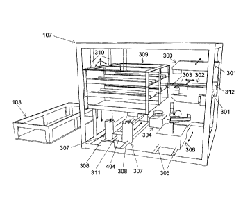
Figs. 3a and 3b show a preferred embodiment of a cell processing rack 107 in
more
detail. In this particular preferred embodiment, the cell processing rack 107
can be
regarded as the heart and soul of the automated cell culture arrangement 100:
the cell
processing rack 107 of Fig. 3a represents an open and accessible support
structure,
which comprises: a bioreactor holder 309 for holding the close cell culture
module or
parts of it, a cell imaging device 300 for visualization of biological cells,
a cell
wash/concentration unit 306 for washing and/or concentration of biological
cells, a
valve actuator 307 for automated handling of valves integrated into the fluid
pathway
of the closed cell culture module and a peristaltic pump 304 for
transportation of
CA 02833001 2013-10-11
WO 2011/130865
PCT/C112011/000088
- 27 -
fluid in the closed cell culture module. The cell imaging device 300 can be
moved in
a horizontal manner (as indicated by the arrows) along to guide bars 301 by
means of
an electrical drive (not shown). Horizontal movement of the cell imaging
device 300
is for example needed to position the cell imaging device in front of a cell
proliferation flask to be analyzed located in the bioreactor holder 309. The
cell
imaging device further carries a bioreactor support structure 303 and a
bioreactor
gripper 302. The bioreactor support structure 303 allows to position and hold
bioreactors or cell culture flasks during visualization at a certain distance
to the main
components of the cell imaging device 300, e.g. the objective of a microscope.
The
bioreactor gripper 302 allows to move a cell proliferation flask from the
bioreactor
holder 309 onto the bioreactor support structure 303 and back. The bioreactor
gripper
moves forward and backwards as indicated by the arrows in figure 3a, by means
of
an electrical drive 312. The bioreactor holder 309 moves up and down along two
guide bars 310 by means of electrical drives (not shown). This vertical
adjustment
allows to align a certain cell culture flask in the bioreactor holder 309 with
the cell
imaging device 300. Such an alignment allows the gripper 302 to pull a cell
culture
flask onto the bioreactor support structure 303 of the cell imaging device
300. An
electrical drive (not shown) preferably rotates the bioreactor holder 309 in
both
directions partially around its longitudinal axis 313 as indicated in figure
3b.
Repeated partial back and forward rotation of the bioreactor holder results in
a
shaking effect, which is e.g. needed to evenly distribute cells in cell
proliferation
flask hold by the bioreactor holder 309. The valve actuator 307 is movable
horizontally (as indicated by the arrows in figure 3) along two guide bars 308
by
means of a thread shaft 311 actuated by an electrical drive 404 (shown in
figure 4).
Horizontal movement of the valve actuator is required to position the valve
actuator
below the valve, which needs to be actuated. The cell wash/collection device
306, for
example a centrifuge, is movable horizontally (as indicated by the arrows)
along two
guide bars 305, a thread shaft (not shown) and an electrical drive (not
shown). Figure
3b shows for illustration purposes the cell wash/cell collection device 306
twice,
once in its operation position 0 and once in its park position P. When not in
use the
CA 02833001 2013-10-11
WO 2011/130865
PCT/C112011/000088
- 28 -
cell wash/cell collection device 306 is moved into its park position P in
order to clear
the space for the cell imaging device 300, which is also moveable in
horizontal
direction. In figure 3b, the cell imaging device 300 is shown in its park
position (P).
Due to the modular design of the cell processing rack 107 it is possible to
disassemble the rack into its single components (cell imaging device such as
microscope and camera, bioreactor holder, cell wash/concentration unit such as
a
centrifuge, bioreactor holder, valve actuator) in order to facilitate cleaning
or
servicing and exchanging said components in case of failure or for a different
cell
growth protocol or application. For ease of use during loading of the closed
cell
culture module and the tool modules to the cell processing rack 107, it can be
removed from the cell processing unit 105, either as stand-alone component or
in
conjunction with the cell maintenance rack 103 being removed at the same time
from
the cell maintenance unit.
This type of preferred embodiments of the automated cell culture arrangement
as
described in the figures 1-3b are designed for the use of automated and
standardized
cultivation of biological cells in vitro including at least the following
critical cell
culture process steps: isolation of cells out of a tissue biopsy or any other
cell source,
seeding of cells on planar surfaces or 3D structures for multiplication of
cells over
one or more passages, release and harvest of cells following expansion,
washing and
concentration of cells, as well as seeding and growth of cells in various 3D
arrangements, which support the generation of de novo tissue.
Fig. 4 and Fig. 5 show an example of valve actuator in a front view and in a
side
view, respectively. The purpose of the valve actuator 307 is to actuate, for
example,
up to twenty 3-way valves, which are preferably arranged in two rows. Each
valve
1005 can be set to three different positions by the valve actuator. Changing
from one
CA 02833001 2013-10-11
WO 2011/130865 PCT/CH2011/000088
- 29 -
position to the next valve position requires a 90 degree rotation of the valve
handle
400. The valve actuator is shown with a mounted valve manifold 1003. A series
of 3-
way valves 1005 are integrated in the valve manifold 1003. The valve manifold
is not
part of the valve actuator but it is a discrete part of the closed cell
culture module
.. 200. The valve manifold 1003 is clipped to the valve actuator by means of
manifold
holders 500 shown in figure 5. The valve actuator includes two valve handle
counterparts 401. The valve handle counterparts 401 can be moved below the
valve
manifolds 1003 in horizontal direction. The movement is guided by the valve
actuator guide bars 308, which are in a parallel orientation to the valve
manifold
1003. The electrical drive 404 rotates a thread shaft 311. A female thread
turns the
rotary movement of the thread shaft 311 into a linear movement of the block
consisting of valve handle counter parts 401 and electrical drives 402 and
403. The
valve handle counter parts 401 can be vertically moved up via an electrical
actuator
402. In its upper position, the valve handle counterpart 401 is engaged with a
valve
handle 400 of the valve to be actuated. Electrical drive 403 allows to rotate
the valve
handle counterpart 401 and thereby the valve handle 400 up to, for example,
180
degrees. The two end points of the rotation are determined by mechanical
stops.
After actuation of a valve the valve handle counterpart is moved down by means
of
electrical drive 402. In figures 4 and 5, the valve handle counterpart 401 is
shown in
.. its lowered position.
Fig. 6a shows a right side sectional view of a cell imaging device and Fig. 6b
shows
a front view of the same cell imaging device but connected to a cell
processing rack.
The cell imaging device is in this example a phase contrast microscope with a
specially deflected light path. 614. The dimensions of the shown microscope
are
about 21cm in height, 8cm in width and 30cm in depth. Light emitted by a lamp
601
passes collector lenses 602, subsequently a phase contrast annulus 603. Light
passing
the phase contrast annulus 603 is deflected by about 90 degrees by a first
tilted
mirror 604. The specimen to be observed (cell proliferation flask) is
positioned in
specimen area 606. The light path enters the microscope again via phase
contrast
CA 02833001 2013-10-11
WO 2011/130865
PCT/C112011/000088
- 30 -
object lens 607. The light path is then again deflected by about 90 degrees by
a
second tilted mirror 608. The microscopical phase contrast image can then be
captured by means of a digital camera 609. The hooks 600 allow to hang the
cell
imaging unit respective microscope into a cell processing rack. Figure 6b
shows the
.. same microscope connected to the frame of a cell processing rack 107. The
microscope has in its back end two bore holes 611, in which the guide bars 301
get
inserted when the microscope is hooked into the cell processing rack 107.
Thread
shaft 612 gets inserted into the thread whole 610 if the microscope when
connected
to the cell processing rack 107. The cell imaging device or microscope can be
moved
along the two guide bars 301. The electrical drive 613 rotates a thread shaft
612.
Female thread 610 turns the rotary movement of the thread shaft 612 into a
linear
movement of the entire cell imaging device respective the microscope.
Fig. 7 shows a sectional view of cell wash/cell collection device. The cell
wash/collection device consists in this example of a centrifuge with a
centrifugation
vessel inclination mechanism 706 and an installed centrifugation vessel 705.
The
centrifugation vessel 705 includes an integrated pipette 800 and pipette
moving
mechanism 803. The centrifugation vessel 705 is also a part of the closed cell
culture
module 200. The centrifugation vessel 705 is connected to the rest of the
closed cell
culture module 200 via a connection tube 700a. The centrifugation vessel 705
is held
by the centrifugation vessel holder 710. Centrifugation vessel holder 710 is
rotatably
connected to the centrifugation shaft 709 via a bearing 704. This bearing 704
keeps
the inclination angle of the centrifugation vessel holder 710 adjustable. The
centrifugation shaft 709 together with the centrifugation vessel holder 710
and the
mounted centrifugation vessel 705 are rotated during centrifugation. An
electrical
drive, which actuates the centrifugation shaft 709 is not shown.
Embroilment of the connecting tube 700a during centrifugation is prevented by
tube
bearing 712. A stainless steel tube 701 is inserted into the flexible
connection tube
CA 02833001 2013-10-11
WO 2011/130865
PCT/CH2011/000088
-31 -
700a. The stainless steel tube 701 again is inserted into a Teflon tube
connector 703.
An 0-ring 702 presses the upper thin walled part of the Teflon tube connector
703
against the stainless steel tube 701 and ensures thereby leak tightness of the
entire
tube bearing 712. The stainless steel tube 701 as well as the connected
flexible tube
700a are not rotating during centrifugation, while the Teflon tube connector
703 and
the connected flexible tube 700b are rotating together with centrifugation
shaft 709,
centrifugation vessel holder 710 and centrifugation vessel 705. The tube
bearing 712
and the entire centrifugation vessel 705 are part of the closed cell culture
module
200. The tube bearing 712 is clipped into the centrifugation shaft 709 during
installation of the closed cell culture module in cell a processing rack 107,
prior to
the start of a biological process.
The centrifugation vessel inclinator 706 and pipette actuator wheel 707 are
not used
during centrifugation but they are used during filling and draining of the
centrifugation vessel 705. The centrifugation vessel inclinator 706 can be
vertically
moved as indicated by the arrows in Fig. 7. A thread shaft 708 is positioned
in
thread hole 711 of the centrifugation vessel inclinator 706. Rotation of the
thread
shaft 708 by an electrical drive (not shown) lifts or countersinks the
centrifugation
vessel inclinator 706. Lifting of the centrifugation vessel inclinator 706
results, at a
certain level, in an engagement of the pipette moving mechanism 803 of the
centrifugation vessel 705 with the pipette actuator wheel 707. Further lifting
of the
centrifugation vessel inclinator 706 changes the inclination angle of the
centrifugation vessel 705. (L) and (U) in figure 7 indicate two different
inclinations
of the cell centrifugation vessel 705. Engagement of the pipette moving
mechanism
803 with the pipette actuator wheel 707 allows also to sink and countersink
the
pipette 800 within the centrifugation vessel 705. Rotation of the pipette
actuator
wheel 707 actuates the pipette moving mechanism 803, which again lowers or
lifts
the pipette 800. A coordinated actuation of the centrifugation vessel
inclinator 706
and the pipette movement mechanism 803 allows to reproduce the movements
applied during manual pipetting.
CA 02833001 2013-10-11
WO 2011/130865
PCT/CH2011/000088
- 32 -
Fig. 8 shows a sectional view of an example of a stand-alone centrifuge
vessel. It is
the same centrifugation vessel as shown in Fig. 7 with the only difference
that it is
detached from cell wash/cell collection device. The pipette 800 is clamped
between
two pipette transport wheels 804 within the pipette movement mechanism 803.
Synchronous rotation of the two pipette transport wheel 804 moves the pipette
800
either downwards or upwards as indicated by the arrows. The pipette transport
wheels 804 are actuated (details not shown) by the pipette actuator wheel 707
shown
in figure 7. The pipette 800 gets inserted into the pipette shell 801 when
moved
upwards. The pipette shell 801 ensures that the pipette is not exposed to the
environment and therefore that containment of the closed bioreactor module is
not
impaired when the pipette is in an extracted position. The tube connector 802
connects the flexible connection tube 700b with the pipette shell 801. Removal
or
supply of fluid is even possible if the pipette 800 is completely inserted to
the pipette
shell 801 because there is enough clearance between the outer surface of
pipette 800
and the inner surface of the pipette shell 801 in order to allow fluid flow
from the
flexible tube 700b around and into the pipette 800.
Fig. 9 shows a sectional view of a further example of a centrifuge vessel.
This
version of a centrifugation vessel uses a flexible gaiter to protect the
pipette 800 from
exposure to the environment when the pipette is moved out of the vessel. The
mechanism to move the pipette up- or downwards is not shown. This could be a
gripper, which grasps the pipette above the gaiter 900 and which is capable
lowering
or lifting the pipette as indicated by the arrows. Alternatively, the gaiter
arrangement
can be combined with a pipette movement mechanism 803 as in the preceding
Figure.
Fig. 10 shows a scheme of an example of the closed cell culture module.
The entire biological process takes place in the closed cell culture module.
Once the
cell culture module has been assembled, biological material and process fluids
are
CA 02833001 2013-10-11
WO 2011/130865
PCT/C112011/000088
- 33 -
added and the cell culture module is preferably installed in the cell
processing rack
107 and the cell maintenance rack 103. The closed cell culture module is not
surrounded by a housing in order to allow visibility and easy access to its
different
components. The closed cell culture module 200 comprises a fluid circuit and a
number of vessels and bioreactors connected to the fluid circuit. The fluid
circuit as
shown in this particular scheme of Fig 10 consists of a number of 3-way valves
1005
integrated into two manifold rows 1003, a sterile air filter 1010 connected to
one of
the valves 1005 and two manifold connection tubes 1004, which connect the two
valve manifolds 1003. The sterile air filter 1010 allows to suck air into the
pathway
and thereby to drain valve manifolds and connecting tubes into a desired
vessel. A
cell culture module preferably includes but is not limited to some or all of
the
following vessels/bioreactors: a cell isolation vessel 1007, one or more
proliferation
bioreactors 1006, a medium conditioning reservoir 1001, one or more sample
vials
1008, a centrifugation vessel 705 and differentiation bioreactor 1000. The
bioreactors/vessels are connected to the valves 1005 via vessel connection
tubes
1009 and couplings (not shown). This setup allows to tailor the closed cell
culture
module to specific culture approaches, cell types and the type of culture
processes to
be performed. The process steps, which can be performed in the closed cell
culture
module include but are not limited to all or some of the following steps:
isolation of
cells from a biopsy, proliferation of cells, cell harvest, cell washing and
concentration, seeding and cultivation of cells on a biomaterial scaffold or
membrane. Depending on the steps required for a desired process and according
to
different user preferences the closed cell culture module is assembled with a
variable
collection of bioreactors and vessels connected to the basic circuit. For
example, the
medium storage flasks 1002 can be of different size, depending on the volumes
of
media required for a particular process. The medium storage flasks 1002 might
be
filled with solutions like e.g. collagenase, proliferation media, cell
detachment
media, cell wash solution or a cell storage solution. A preferred embodiment
of the
cell isolation chamber 1007 comprises a lid including a sterile filter and an
in/outlet
port at the bottom of the chamber. The chamber has a conical shape to support
CA 02833001 2013-10-11
WO 2011/130865
PCT/C112011/000088
- 34 -
draining. Tissue needed for cell isolation is placed in the cell isolation
vessel prior to
the process start. Proliferation flasks 1006 are available in different sizes
and selected
depending on the number of cells to be proliferated. The sterile air filter as
part of the
lid allows supply of cells and media in the bioreactor with oxygen and CO2 but
also
draining and filling of the bioreactor via inlet/outlet port. The inlet/outlet
is at the
lowest point of the inclined rear wall of the cell proliferation flasks 1006
in order to
support draining. The incorporation of a pH arid/or 02 sensor (not shown) into
the
closed cell culture module allows tracking media consumption over time and
triggering exchange of media. Parameters like the 02 consumption rate or pH
change
rate are preferably measured as part of the monitoring of the cell growth
within the
proliferation bioreactor. The 3D culture bioreactor 1000 will allow to seed
cells on to
a selected biomaterial e.g. scaffold in order to process or cultivate cells
towards a
preformed tissue. Obviously, the selection of the kind and number of
components
forming the closed cell culture module and the arrangement of the components
is
highly variable for different embodiments according to the invention and Fig.
10
merely discloses one example.
Fig. 11 is a perspective view of an example of an automated cell culture
arrangement, in which a plurality of individual closed cell culture modules
configured on cell maintenance racks 1101 and/or cell processing racks 1109
are
accommodated for example by vertical stacking as shown. In this particular
example
of the automated cell culture arrangement up to 5 individual cell maintenance
racks
1101 and/or cell processing racks 1109 can be accommodated. The shown cell
culture arrangement is therefore able to run up to 5 independent processes in
up to 5
independent closed cell culture modules. Each cell maintenance rack 1101 is
located
in a separate cell maintenance unit 1100. Preferably, the cell maintenance
units 1100
are separated, as shown, however in other embodiments the cell maintenance
units
are interconnected. Each cell processing rack 1103 has its own level 1109 in
the
common cell processing unit 1102 space. Peristaltic pumps 1106 and valve
actuators
1110 are tools modules, which are frequently used during a biological process.
Each
CA 02833001 2013-10-11
WO 2011/130865
PCT/C112011/000088
- 35 -
cell processing rack 1109 is provided with its own peristaltic pump 1109 and
valve
actuator 1110. Cell imaging device 1104 and cell wash/concentration device
1105
are not often used during a biological process. One cell imaging device 1104
and one
cell wash/concentration device 1105 is sufficient to serve 5 biological
processes
running parallel. A cell imaging device 1104 and a cell wash/concentration
device
1105 are located in an elevator shaft 1101. A movable carrier such as an
elevator (not
shown) transports the cell imaging device 1104 and the cell wash/concentration
device 1105 to each cell processing unit level 1109 and the respective cell
processing
rack 1103. A software coordinates process steps performed in order to avoid
conflicts
with respect to the use of the common tool modules located in the elevator
shaft. In
preferred embodiments the elevator shaft is a predetermined space available in
each
of the cell processing racks as shown in Fig.11. In other preferred
embodiments the
elevator shaft is a predetermined space of the automated cell culture
arrangement
preferably being within the processing rack of the processing unit of the cell
culture
arrangement.
DESCRIPTION OF EXAMPLE PROCESS
The following section describes an example of an application of the automated
cell
culture arrangement performing a cell culture process in an automated manner.
The
.. chosen example process includes the isolation of cells from a tissue
biopsy,
proliferation of these cells, harvest of the proliferated cells, purification
and
concentration of the harvested cells. This example process shows how the
different
elements of this invention may be used in a process and how they may interact.
However, the automated cell culture arrangement is not at all limited to the
described
.. example process but is applicable to a large range of other processes.
CA 02833001 2013-10-11
WO 2011/130865 PCT/C112011/000088
- 36 -
Transportation of fluid from one vessel to another vessel in the closed cell
culture
module 200 requires correct setting of corresponding valves 1005. Setting of
the
valves by the valve actuator 307 is assumed to be known from standard
techniques in
the art and not described below.
Process activities requiring manual handling
Manual preparation of the closed cell culture module 200 in a sterile
environment:
¨ Cell detachment medium is filled into flask 1002c
¨ Proliferation medium is filled into flask 1002d
¨ Cell isolation medium is filled into flask 1002e
¨ Tissue biopsy is put into cell isolation vessel 1007
Manual installation of the closed cell culture module 200 on the cell
processing rack
107 and the cell maintenance rack 103:
¨ Medium storage flasks 1002 are placed on the cell maintenance rack
¨ Cell proliferation flasks 1006 and cell isolation vessel are fixed on the
bioreactor
holder 309.
¨ The valve manifold 1003 is installed on the valve actuator 307
¨ A manifold connection tube is connected to the peristaltic pump 304
¨ The Centrifugation vessel is clipped to the centrifugation vessel holder
710 of the
cell wash/collection device 306.
Final preparation of the automated cell culture arrangement:
¨ The cell processing rack is inserted into the cell processing unit of the
housing
106.
¨ The cell maintenance rack is inserted into the cell maintenance unit of the
housing 106.
¨ Door 102 of the automated cell culture arrangement is closed.
¨ Process parameters are entered via user interface 101.
CA 02833001 2013-10-11
WO 2011/130865
PCT/CH2011/000088
- 37 -
¨ Process is started via user interface 101.
Process activities performed within the automated cell culture arrangement
Tissue biopsy digest:
¨ Cell isolation medium is pumped from flask 1002e into cell isolation
vessel 1007.
¨ Sterile air entering the fluid pathway via sterile filter 1010 is pumped
into cell
isolation vessel in order to drain the fluid pathway.
¨ Cell isolation vessel is gently agitated by the bioreactor holder 309 for
a specified
time period. Enzymes contained in the cell isolation medium digest the tissue
matrix, whereby the cells get released into the medium.
¨ The cell isolation medium including the suspended cells is pumped from
the cell
isolation vessel 1007 into the centrifugation vessel 705.
Cell wash and cell concentration following tissue biopsy digest:
¨ Cell imaging device 300 is moved into park position P and cell
wash/collection
device 306 is moved into operation position 0.
¨ The isolated cells are collected as a pellet in the cone of the
centrifugation vessel
705 by centrifugation with cell wash/cell collection device 306,
¨ The supernatant is removed via pipette 800 and pumped into waste flask
1002a.
The following elements work in coordinated manner in order to avoid re-
suspension and removal of the pelleted cells: Peristaltic pump 304, pipette
moving mechanism 803 and centrifugation vessel inclinator 706.
¨ Cell proliferation medium is pumped from the corresponding flask 1002d
into the
centrifugation vessel 705. The pelleted cells are now re-suspended in the
added
proliferation medium e.g. by intense back and forward pumping of the
proliferation medium and/or by fast up and down movement of the centrifugation
vessel inclinator 706.
CA 02833001 2013-10-11
WO 2011/130865
PCT/C112011/000088
- 38 -
¨ The washed and suspended cells are pumped from centrifugation vessel 705
into
one or several proliferation flasks 1006g (dependent on a specified seeding
density to be achieved).
.. Cell proliferation (PO):
¨ The cells are homogeneously distributed within the selected proliferation
flask(s)
1006g via gently agitating the bioreactor holder 309 for approximately 1
minute..
¨ The cells remain now in the proliferation flask(s) 1006g until they have
grown to
a pre-defined level of cellular confluence (up to several weeks).
.. ¨ The cell density is analyzed daily by the cell imaging device 300 and the
proliferation medium in the proliferation flask is exchanged every 2-3 days by
fresh proliferation medium. The medium exchange can occur in regular intervals
or it can be triggered by medium properties (e.g. pH value) measured by an
integrated sensor.
Cell density check during cell proliferation.
¨ The cell wash/collection device 306 is moved into its park position P
whereas the
cell imaging device 300 is moved to a position opposite of the respective cell
proliferation flask 1006g to be monitored.
¨ The vertical position of the bioreactor holder 309 is adjusted in a way
that the
proliferation flask 1006g is aligned with the cell imaging device 300.
¨ The bioreactor gripper grips the proliferation flask 1006g and pulls it
on to the
bioreactor support of the microscope.
¨ Digital camera 609 captures a microscopical image of the cells inside the
proliferation flask 1006g. Cell density is then analyzed by an image analysis
software. Pictures at different locations in the flasks can be captured, if
the
position of the proliferation flask 1006g is changed by the bioreactor gripper
302
and/or by change of the position of the cell imaging device relative to the
proliferation flask 1006g.
CA 02833001 2013-10-11
WO 2011/130865
PCT/C112011/000088
- 39 -
Medium exchange during cell proliferation:
¨ Used medium is pumped from the selected cell proliferation flask 1006g
into
waste flask I 002a.
¨ Fresh medium is pumped from the proliferation medium flask 1002d into the
proliferation flask 1006g.
Cell harvest at the end of cell proliferation:
¨ Upon achievement of a desired cell density in one or several
proliferation flasks,
cellular detachment and harvest will occur from the respective proliferation
flask(s) 1006g.
¨ The selected proliferation flask 1006g will be emptied by pumping the
proliferation medium into the waste flask 1002a.
¨ Cell release medium is now pumped from the cell release medium flask
1002c
into proliferation flask 1006g. The enzymes contained in the cell release
medium
release the cells from the floor of the proliferation flask.
¨ Release of the cells is further supported by some intense impacts caused by
the
bioreactor gripper 302. The bioreactor gripper 302 grips the proliferation
flask
and performs a fast acceleration followed by a sudden stop. The course of the
cell
detachment process is monitored by the cell imaging device 300.
¨ The cells are now suspended in the cell release medium. The cell release
medium
harms the cells and needs to be removed from the cells as soon as possible.
The
cell release medium including the cells is therefore transferred into the
centrifugation vessel 705.
Cell wash and cell concentration following initial cell proliferation PO:
¨ The cells are centrifuged and re-suspended in fresh (proliferation) medium
by
using essentially the same procedure as already explained further above.
Cell proliferation (PI, P2 etc.):
CA 02833001 2013-10-11
WO 2011/130865 PCT/C112011/000088
- 40 -
¨ Dependent on the number of cells finally required, the cells can now be
subjected
to additional proliferation cycles. The procedure is essentially the same as
described for the initial proliferation cycle PO.
Removal of the cells from the automated cell culture system:
¨ Following performing the final cell proliferation cycle including cell
wash and
concentration, the suspended cells are pumped from the centrifugation vessel
into
a cell storage vessel, which is placed in the refrigerated cell maintenance
unit
104. The cells remain in the cell maintenance unit until they are removed from
the system by a user.
General remarks: During a process it is always possible to pump a medium
sample or
cell suspension sample into one of the sample vessels 1008 located in the
refrigerated
cell maintenance unit. A user can then harvest such a sample vessel by
separating it
from the closed cell culture module 200 via the use of aseptic connections
(not
shown). It is also imaginable that said sample vessel 1008 or similar would be
the
integral part of a second automated device (e.g. cell counter or sterility
testing
device) to include even cell counting and sterility testing into the described
biological process in an automated end to and manner.
List of Reference Signs
100 Automated cell culture arrangement
101 User Interface
102 Door (only partly shown)
106 Housing
108 Connection for CO2
109 Connection for power supply
110 Connection for data network
CA 02833001 2013-10-11
WO 2011/130865
PCT/C112011/000088
- 41 -
III Connection for sterilization gas
200 Closed cell culture module
301 Cell imaging unit guide bar
302 Bioreactor gripper
303 Bioreactor support
305 Cell wash/cell concentration device guide bar
306 Cell wash/cell concentration device
307 Valve actuator
308 Valve actuator guide bars
309 Bioreactor holder
310 Bioreactor holder guide bars
311 Threaded shaft for horizontal movement of valve actuator
312 Electrical drive for bioreactor gripper
313 Bioreactor holder longitudinal axis
400 3-way valve handle
401 Valve handle counter part
402 Electrical drive for vertical movement of the valve handle counter
part
403 Electrical drive for rotation of valve
404 Electrical drive for horizontal movement of valve actuator
500 Manifold holder
501 Female tread
600 Cell imaging device hook
601 Lamp
602 Collector lens
603 Phase contrast annulus
604 Tilted mirror (Condenser side)
605 Condenser lens
606 Specimen area
607 Phase contrast object lens
608 Tilted mirror (Object lens side)
609 Digital camera
610 Treaded hole
611 Bore hole for guide bar
612 Cell imaging device actuator treaded shaft
613 Electrical drive for horizontal movement of the Cell imaging device
614 light path
701 Stainless steel tube
702 0-ring
703 Teflon tube connector
704 Centrifugation vessel holder bearing
705 Centrifugation vessel
CA 02833001 2013-10-11
WO 2011/130865
PCT/C112011/000088
-42-
706 Centrifugation vessel inclinator
707 Pipette actuator wheel
708 Centrifugation vessel inclinator thread shaft
709 Centrifuge shaft
710 Centrifugation vessel holder
711 Female tread
712 Tube bearing
800 Pipette
801 Pipette shell
802 Tube connector
803 Pipette moving mechanism
804 Pipette transport wheels
900 Gaiter
1000 Differentiation bioreactor
1001 Medium conditioning reservoirs
1002 Medium storage flasks
1003 Manifold
1004 Manifold connection tube1005
1005 3-way valve
1006 Cell proliferation flasks
1007 Cell isolation vessel
1008 Sample vessel
1009 Vessel connection tube
1010 Sterile air filter
1100 Cell maintenance unit
1105 Cell wash/collection device
1108 Elevator shaft
1109 Cell processing unit level
1100; 104 Cell maintenance unit
1101; 103 Cell maintenance rack
1102; 105 Cell processing unit
1103; 107 Cell processing rack
1104; 300 Cell imaging device
1106; 304 Peristaltic Pump
1110; 307 Valve actuator
700a Flexible Tube (not rotating)
700b Flexible (rotating)