Note: Descriptions are shown in the official language in which they were submitted.
CA 02833085 2013-10-11
WO 2012/143567 PCT/EP2012/057408
- 1 -
PROCE S S FOR CONVERTING A SOLID BIOMASS MATERIAL
FIELD OF THE INVENTION
The invention relates to a process for converting a
solid biomass material and a process for producing a
biofuel and/or biochemical.
BACKGROUND TO THE INVENTION
With the diminishing supply of crude mineral oil,
use of renewable energy sources is becoming increasingly
important for the production of liquid fuels. These fuels
from renewable energy sources are often referred to as
biofuels.
Biofuels derived from non-edible renewable energy
sources, such as cellulosic materials, are preferred as
these do not compete with food production. These biofuels
are also referred to as second generation, renewable or
advanced, biofuels. Most of these non-edible renewable
energy sources, however, are solid materials that are
cumbersome to convert into liquid fuels.
For example, the process described in WO 2010/062611
for converting solid biomass to hydrocarbons requires
three catalytic conversion steps. First the solid biomass
is contacted with a catalyst in a first riser operated at
a temperature in the range of from about 50 to about
200 C to produce a first biomass-catalyst mixture and a
first product comprising hydrocarbons (referred to as
pretreatment). Hereafter the first biomass-catalyst
mixture is charged to a second riser operated at a
temperature in the range of from about 200 to about
400 C to thereby produce a second biomass-catalyst
mixture and a second product comprising hydrocarbons
(referred to as deoxygenating and cracking); and finally
the second biomass-catalyst mixture is charged to a third
CA 02833085 2013-10-11
WO 2012/143567 PCT/EP2012/057408
- 2 -
riser operated at a temperature greater than about 450 C
to thereby produce a spent catalyst and a third product
comprising hydrocarbons. The last step is referred to as
conversion to produce the fuel or specialty chemical
product. WO 2010/062611 mentions the possibility of
preparing the biomass for co-processing in conventional
petroleum refinery units. The process of WO 2010/062611,
however, is cumbersome in that three steps are needed,
each step requiring its own specific catalyst.
W02010/135734 describes a method for co-processing a
biomass feedstock and a refinery feedstock in a refinery
unit comprising catalytically cracking the biomass
feedstock and the refinery feedstock in a refinery unit
comprising a fluidized reactor, wherein hydrogen is
transferred from the refinery feedstock to carbon and
oxygen of the biomass feedstock. In one of the
embodiments W02010/135734 the biomass feedstock comprises
a plurality of solid biomass particles having an average
size between 50 and 1000 microns. In passing, it is
further mentioned that solid biomass particles can be
pre-processed to increase brittleness, susceptibility to
catalytic conversion (e.g. by roasting, toasting, and/or
torrefication) and/or susceptibility to mixing with a
petrochemical feedstock.
In the article titled "Biomass pyrolysis in a
circulating fluid bed reactor for production of fuels and
chemicals" by A.A. Lappas et al, published in Fuel, vol.
81 (2002), pages 2087-2095, an approach for biomass flash
pyrolysis in a circulating fluid bed (CFB) reactor is
described. The CFB reactor comprised a vertical riser
type reactor (7.08 mm ID). The riser height was 165 cm.
From figure 1, the riser reactor appears to be an
essentially vertical external riser reactor connected via
CA 02833085 2013-10-11
WO 2012/143567 PCT/EP2012/057408
- 3 -
an essentially horizontal cross-over pipe with a stripper
vessel. The vertical external riser reactor and
horizontal cross-over pipe appear connected via a 90
degree junction. In all experiments lignocell HBS 150-500
supplied by Rettenmaier GmbH (particle size 200-400
micrometer) was used as biomass feedstock. In the
conventional biomass pyrolysis tests silica sand was used
as a heat carrier. Catalytic biomass pyrolysis was
performed using a commercial equilibrium FCC catalyst
supplied by a Greek refinery. The Biomass pyrolysis
experiments were performed at riser temperatures in the
range of 400-500 C. Each biomass pyrolysis run required 2
hour for the line out and the heating up of the unit and
3 hours of a steady state operation. Such operation times
are considered to be too short to create any substantial
deposition of catalyst.
It would be an advancement in the art to improve the
above processes further. For example, in order to scale
up the catalytic cracking of the solid biomass feedstock
to a commercial scale, the process may require
improvements to meet nowadays conversion, robustness
maintenance and/or safety requirements.
SUMMARY OF THE INVENTION
Such an improvement has been achieved with the
process according to the invention. It has been
advantageously found that when using an external riser
reactor with a curve and/or low velocity zone at its
upper end, wherein a part of the catalytic cracking
catalyst has deposited in the curve and/or low velocity
zone a safer process that may be operated for a longer
period can be obtained.
Accordingly the present invention provides a process
for converting a solid biomass material, comprising
CA 02833085 2013-10-11
WO 2012/143567 PCT/EP2012/057408
- 4 -
contacting the solid biomass material with a catalytic
cracking catalyst at a temperature of more than 400 C in
a riser reactor to produce one or more cracked products,
wherein the riser reactor is an external riser reactor
with a curve and/or low velocity zone at its termination
and wherein a part of the catalytic cracking catalyst has
deposited in the curve and/or low velocity zone.
Without wishing to be bound by any kind of theory,
it is believed that when connecting an upstream external
riser reactor with a downstream cross-over pipe in a 90
degrees junction (as described by Lappas et al.)
turbulence will be created in the junction.
It has now for the first time been recognized that
such turbulence may cause a problem when a solid biomass
material is converted.
In the process according to the invention the solid
biomass material may be converted into an intermediate
oil product (herein also referred to as pyrolysis oil)
which intermediate oil product in turn can be cracked
into one or more cracked products. Any unconverted solid
biomass material particles, however, may cause erosion of
the hardware due to the above described turbulence.
The process according to the invention, using an
external riser reactor with a curve and/or low velocity
zone wherein a part of the catalytic cracking catalyst
has deposited in the curve and/or low velocity zone
allows one to reduce the risk of erosion, thereby
increasing safety and hardware integrity.
Without wishing to be bound to any kind of theory it
is believed that the curve and/or low velocity zone
reduces the impact by residual solid biomass material
particles and the deposited catalytic cracking catalyst
CA 02833085 2013-10-11
WO 2012/143567 PCT/EP2012/057408
- 5 -
forms a protective layer against erosion by unconverted
solid biomass material particles.
In addition, the curve and/or low velocity zone,
with deposited catalytic cracking catalyst may assist in
reducing corrosion due to oxygen-containing compounds in
the intermediate oil product or in the one or more
cracked products.
The process according to the invention is simple
and may require a minimum of processing steps to convert
a solid biomass material to a biofuel component and/or
biochemical component. Such biofuel component may be
fully fungible.
Furthermore the process according to the invention
may be easily implemented in existing refineries.
In addition, the process according to the invention
does not need any complicated actions, for example it
does not need a pre-mixed composition of the solid
biomass material and the catalyst.
The one or more cracked products produced by the
process according to the invention may be used as an
intermediate to prepare a biofuel and/or biochemical
component.
The biofuel and/or biochemical component(s) may
advantageously be further converted to and/or blended
with one or more further components into novel biofuels
and/or biochemicals.
The process according to the invention therefore
also provides a more direct route via catalytic cracking
of solid biomass material to second generation, renewable
or advanced, biofuels and/or biochemicals.
BRIEF DESCRIPTION OF THE DRAWINGS
Figure 1 shows a schematic diagram of a first
process according to the invention.
CA 02833085 2013-10-11
WO 2012/143567 PCT/EP2012/057408
- 6 -
Figure 2A shows a schematic diagram of specific
embodiment A for the process of figure 1.
Figure 2B shows a schematic diagram of specific
embodiment B for the process of figure 1.
Figure 3 shows a schematic diagram of a second
process according to the invention.
DETAILED DESCRIPTION OF THE INVENTION
By a solid biomass material is herein understood a
solid material obtained from a renewable source. By a
renewable source is herein understood a composition of
matter of biological origin. Preferably the renewable
source is a composition of matter of cellulosic or
lignocellulosic origin as opposed to a composition of
matter obtained or derived from petroleum, natural gas or
coal.
Preferably the renewable source is a composition of
matter of cellulosic or lignocellulosic origin. Any solid
biomass material may be used in the process of the
invention. In a preferred embodiment the solid biomass
material is not a material used for food production.
Examples of preferred solid biomass materials include
aquatic plants and algae, agricultural waste and/or
forestry waste and/or paper waste and/or plant material
obtained from domestic waste.
Preferably the solid biomass material contains
cellulose and/or lignocellulose. Examples of suitable
cellulose- and/or lignocellulose- containing materials
include agricultural wastes such as corn stover, soybean
stover, corn cobs, rice straw, rice hulls, oat hulls,
corn fibre, cereal straws such as wheat, barley, rye and
oat straw; grasses; forestry products and/or forestry
residues such as wood and wood-related materials such as
sawdust; waste paper; sugar processing residues such as
CA 02833085 2013-10-11
WO 2012/143567 PCT/EP2012/057408
- 7 -
bagasse and beet pulp; or mixtures thereof. More
preferably the solid biomass material is selected from
the group consisting of wood, sawdust, straw, grass,
bagasse, corn stover and/or mixtures thereof.
The solid biomass material may have undergone
drying, torrefaction, steam explosion, particle size
reduction, densification and/or pelletization before
being contacted with the catalyst, to allow for improved
process operability and economics.
Preferably the solid biomass material is a torrefied
solid biomass material. In a preferred embodiment the
process according to the invention comprises a step of
torrefying the solid biomass material at a temperature of
more than 200 C to produce a torrefied solid biomass
material that is contacted with the catalytic cracking
catalyst. The words torrefying and torrefaction are used
interchangeable herein.
By torrefying or torrefaction is herein understood
the treatment of the solid biomass material at a
temperature in the range from equal to or more than 200 C
to equal to or less than 350 C in the essential absence
of a catalyst and in an oxygen-poor, preferably an
oxygen-free, atmosphere. By an oxygen-poor atmosphere is
understood an atmosphere containing equal to or less than
15 vol.% oxygen, preferably equal to or less than 10
vol.% oxygen and more preferably equal to or less than 5
vol.% oxygen. By an oxygen-free atmosphere is understood
that the torrefaction is carried out in the essential
absence of oxygen.
Torrefying of the solid biomass material is
preferably carried out at a temperature of more than
200 C, more preferably at a temperature equal to or more
than 210 C, still more preferably at a temperature equal
CA 02833085 2013-10-11
WO 2012/143567 PCT/EP2012/057408
- 8 -
to or more than 220 C, yet more preferably at a
temperature equal to or more than 230 C. In addition
torrefying of the solid biomass material is preferably
carried out at a temperature less than 350 C, more
preferably at a temperature equal to or less than 330 C,
still more preferably at a temperature equal to or less
than 310 C, yet more preferably at a temperature equal to
or less than 300 C.
Torrefaction of the solid biomass material is
preferably carried out in the essential absence of
oxygen. More preferably the torrefaction is carried under
an inert atmosphere, containing for example inert gases
such as nitrogen, carbon dioxide and/or steam; and/or
under a reducing atmosphere in the presence of a reducing
gas such as hydrogen, gaseous hydrocarbons such as
methane and ethane or carbon monoxide.
The torrefying step may be carried out at a wide
range of pressures. Preferably, however, the torrefying
step is carried out at atmospheric pressure (about 1 bar,
corresponding to about 0.1 MegaPascal).
The torrefying step may be carried out batchwise or
continuously.
The torrefied solid biomass material has a higher
energy density, a higher mass density and greater
flowability, making it easier to transport, pelletize
and/or store. Being more brittle, it can be easier
reduced into smaller particles.
Preferably the torrefied solid biomass material has
an oxygen content in the range from equal to or more than
10 wt%, more preferably equal to or more than 20 wt% and
most preferably equal to or more than 30wt% oxygen, to
equal to or less than 60 wt%, more preferably equal to or
CA 02833085 2013-10-11
WO 2012/143567 PCT/EP2012/057408
- 9 -
less than 50 wt%, based on total weight of dry matter
(i.e. essentially water-free matter).
In a further preferred embodiment, any torrefying or
torrefaction step further comprises drying the solid
biomass material before such solid biomass material is
torrefied. In such a drying step, the solid biomass
material is preferably dried until the solid biomass
material has a moisture content in the range of equal to
or more than 0.1 wt% to equal to or less than 25 wt%,
more preferably in the range of equal to or more than 5
wt% to equal to or less than 20 wt%, and most preferably
in the range of equal to or more than 5 wt% to equal to
or less than 15wt%. For practical purposes moisture
content can be determined via ASTM E1756-01 Standard Test
method for Determination of Total solids in Biomass. In
this method the loss of weight during drying is a measure
for the original moisture content.
Preferably the solid biomass material is a
micronized solid biomass material. By a micronized solid
biomass material is herein understood a solid biomass
material that has a particle size distribution with a
mean particle size in the range from equal to or more
than 5 micrometer to equal to or less than 5000
micrometer, as measured with a laser scattering particle
size distribution analyzer. In a preferred embodiment the
process according to the invention comprises a step of
reducing the particle size of the solid biomass material,
optionally before or after such solid biomass material is
torrefied. Such a particle size reduction step may for
example be especially advantageous when the solid biomass
material comprises wood or torrefied wood. The particle
size of the, optionally torrefied, solid biomass material
can be reduced in any manner known to the skilled person
CA 02833085 2013-10-11
WO 2012/143567 PCT/EP2012/057408
- 10 -
to be suitable for this purpose. Suitable methods for
particle size reduction include crushing, grinding and/or
milling. The particle size reduction may preferably be
achieved by means of a ball mill, hammer mill, (knife)
shredder, chipper, knife grid, or cutter.
Preferably the solid biomass material has a particle
size distribution where the mean particle size lies in
the range from equal to or more than 5 micrometer
(micron), more preferably equal to or more than 10
micrometer, even more preferably equal to or more than 20
micrometer, and most preferably equal to or more than 100
micrometer to equal to or less than 5000 micrometer, more
preferably equal to or less than 1000 micrometer and most
preferably equal to or less than 500 micrometer.
Most preferably the solid biomass material has a
particle size distribution where the mean particle size
is equal to or more than 100 micrometer to avoid blocking
of pipelines and/or nozzles. Most preferably the solid
biomass material has a particle size distribution where
the mean particle size is equal to or less than 3000
micrometer to allow easy injection into the riser
reactor.
For practical purposes the particle size
distribution and mean particle size of the solid biomass
material can be determined with a Laser Scattering
Particle Size Distribution Analyzer, preferably a Horiba
LA950, according to the ISO 13320 method titled "Particle
size analysis - Laser diffraction methods".
Hence, preferably the process of the invention
comprises a step of reducing the particle size of the
solid biomass material, optionally before and/or after
torrefaction, to generate a particle size distribution
having a mean particle size in the range from equal to or
CA 02833085 2013-10-11
WO 2012/143567 PCT/EP2012/057408
- 11 -
more than 5, more preferably equal to or more than 10
micron, and most preferably equal to or more than 20
micron, to equal to or less than 5000 micron, more
preferably equal to or less than 1000 micrometer and most
preferably equal to or less than 500 micrometer to
produce a micronized, optionally torrefied, solid biomass
material.
In an optional embodiment the particle size
reduction of the, optionally torrefied, solid biomass
material is carried out in the presence of a liquid
hydrocarbon and/or water, to improve processibility
and/or avoid dusting. Most preferably such a liquid
hydrocarbon is the same as the fluid hydrocarbon
envisaged for the fluid hydrocarbon feed in process of
the invention. Examples of such a liquid hydrocarbon
include mineral oil fractions such as long and short
residue.
In a preferred embodiment the, optionally micronized
and optionally torrefied, solid biomass material is dried
before being supplied to the riser reactor. Hence, if the
solid biomass material is torrefied, it may be dried
before and/or after torrefaction. If dried before use as
a feed, the solid biomass material is preferably dried at
a temperature in the range from equal to or more than
50 C to equal to or less than 200 C, more preferably in
the range from equal to or more than 80 C to equal to or
less than 150 C. The, optionally micronized and/or
torrefied, solid biomass material is preferably dried for
a period in the range from equal to or more than 30
minutes to equal to or less than 2 days, more preferably
for a period in the range from equal to or more than 2
hours to equal to or less than 24 hours.
CA 02833085 2013-10-11
WO 2012/143567 PCT/EP2012/057408
- 12 -
In addition to the, optionally micronized and/or
optionally torrefied, solid biomass material preferably
also a fluid hydrocarbon feed is contacted with the
catalytic cracking catalyst in the riser reactor. This
fluid hydrocarbon feed can be co-feeded to the external
riser reactor and may hereafter also be referred to as
fluid hydrocarbon co-feed.
The fluid hydrocarbon feed and the, optionally
micronized and/or optionally torrefied, solid biomass
material can be mixed prior to entry into the riser
reactor or they can be added separately, at the same
location or different locations to the riser reactor.
In one embodiment the fluid hydrocarbon feed and
the, optionally micronized and/or optionally torrefied,
solid biomass material are not mixed together prior to
entry into the riser reactor. In this embodiment the
fluid hydrocarbon feed and the solid biomass material may
be fed simultaneously (that is at one location) to the
riser reactor, and optionally mixed upon entry of the
riser reactor; or, alternatively, the fluid hydrocarbon
feed and the solid biomass material may be added
separately (at different locations) to the riser reactor.
Riser reactors can have multiple feed inlet nozzles. The
solid biomass material and the fluid hydrocarbon feed can
therefore be processed in the riser reactor even if both
components are not miscible by feeding each component
through a separate feed inlet nozzle.
In one preferred embodiment the solid biomass
material is introduced to the riser reactor at a location
downstream of a location where a fluid hydrocarbon feed
is introduced to the riser reactor. Without wishing to be
bound by any kind of theory it is believed that by
allowing the fluid hydrocarbon feed to contact the
CA 02833085 2013-10-11
WO 2012/143567 PCT/EP2012/057408
- 13 -
catalytic cracking catalyst first, hydrogen may be
generated. The availability of this hydrogen may assist
in the reduction of coke formation when the solid biomass
material is contacted with the catalytic cracking
catalyst more downstream in the riser reactor.
In another preferred embodiment the solid biomass
material is introduced into the riser reactor at a
location upstream of the location where the fluid
hydrocarbon feed is introduced. This advantageously
allows for a longer residence time for the solid biomass
material. In addition the solid biomass material can take
advantage of the higher temperature and higher catalyst
to feed weight ratio at that location. The supply of a
solid biomass material into the riser reactor at a
location upstream of a location where a fluid hydrocarbon
feed is introduced may advantageously increase the
conversion of the solid biomass material.
In another embodiment a fluid hydrocarbon feed and
the solid biomass material are mixed together prior to
entry into the riser reactor to provide a slurry feed
comprising the fluid hydrocarbon feed and the solid
biomass material. This advantageously allows for easier
feeding of the solid biomass material to the riser
reactor.
By a hydrocarbon feed is herein understood a feed
that contains one or more hydrocarbon compounds. By
hydrocarbon compounds are herein understood compounds
that contain both hydrogen and carbon and preferably
consist of hydrogen and carbon. By a fluid hydrocarbon
feed is herein understood a hydrocarbon feed that is not
in a solid state. The fluid hydrocarbon co-feed is
preferably a liquid hydrocarbon co-feed, a gaseous
hydrocarbon co-feed, or a mixture thereof. The fluid
CA 02833085 2013-10-11
WO 2012/143567 PCT/EP2012/057408
- 14 -
hydrocarbon co-feed can be fed to a catalytic cracking
reactor (here the riser reactor) in an essentially liquid
state, in an essentially gaseous state or in a partially
liquid-partially gaseous state. When entering the riser
reactor in an essentially or partially liquid state, the
fluid hydrocarbon co-feed preferably vaporizes upon entry
and preferably is contacted in the gaseous state with the
catalytic cracking catalyst and/or the solid biomass
material.
For hydrocarbon co-feeds that are highly viscous, it
may be advantageous to preheat such feeds before entering
the catalytic cracking reactor. For example, hydrocarbon
co-feeds such as a long residue, a vacuum gas oil and/or
mixtures thereof may be preheated to a temperature equal
to or above 250 C.
The fluid hydrocarbon feed can be any non-solid
hydrocarbon feed known to the skilled person to be
suitable as a feed for a catalytic cracking reactor. The
fluid hydrocarbon feed can for example be obtained from a
conventional crude oil (also sometimes referred to as a
petroleum oil or mineral oil), an unconventional crude
oil (that is, oil produced or extracted using techniques
other than the traditional oil well method) or a
renewable oil (that is, oil derived from a renewable
source, such as pyrolysis oil, vegetable oil and/or a
liquefied biomass), a Fisher Tropsch oil (sometimes also
referred to as a synthetic oil) and/or a mixture of any
of these.
In one embodiment the fluid hydrocarbon feed is
derived from a, preferably conventional, crude oil.
Examples of conventional crude oils include West Texas
Intermediate crude oil, Brent crude oil, Dubai-Oman crude
CA 02833085 2013-10-11
WO 2012/143567 PCT/EP2012/057408
- 15 -
oil, Arabian Light crude oil, Midway Sunset crude oil or
Tapis crude oil.
More preferably the fluid hydrocarbon feed comprises
a fraction of a, preferably conventional, crude oil or
renewable oil. Preferred fluid hydrocarbon feeds include
straight run (atmospheric) gas oils, flashed distillate,
vacuum gas oils (VGO), coker gas oils, diesel, gasoline,
kerosene, naphtha, liquefied petroleum gases, atmospheric
residue ("long residue") and vacuum residue ("short
residue") and/or mixtures thereof. Most preferably the
fluid hydrocarbon feed comprises a long residue and/or a
vacuum gas oil.
In one embodiment the fluid hydrocarbon feed
preferably has a 5 wt% boiling point at a pressure of 1
bar absolute (corresponding to 0.1 MegaPascal), as
measured by means of distillation as based on ASTM D86
titled "Standard Test Method for Distillation of
Petroleum Products at Atmospheric Pressure", respectively
as measured by on ASTM D1160 titled "Standard Test
Method for Distillation of Petroleum Products at Reduced
Pressure", of equal to or more than 100 C, more
preferably equal to or more than 150 C. An example of
such a fluid hydrocarbon feed is vacuum gas oil.
In a second embodiment the fluid hydrocarbon feed
preferably has a 5 wt% boiling point at a pressure of 1
bar absolute (corresponding to 0.1 MegaPascal), as
measured by means of distillation based on ASTM D86
titled "Standard Test Method for Distillation of
Petroleum Products at Atmospheric Pressure", respectively
as measured by on ASTM D1160 titled "Standard Test
Method for Distillation of Petroleum Products at Reduced
Pressure", of equal to or more than 200 C, more
preferably equal to or more than 220 C, most preferably
CA 02833085 2013-10-11
WO 2012/143567 PCT/EP2012/057408
- 16 -
equal to or more than 240 C. An example of such a fluid
hydrocarbon feed is long residue.
In a further preferred embodiment equal to or more
than 70 wt%, preferably equal to or more than 80 wt%,
more preferably equal to or more than 90 wt% and still
more preferably equal to or more than 95 wt% of the fluid
hydrocarbon feed boils in the range from equal to or more
than 150 C to equal to or less than 600 C at a pressure
of 1 bar absolute (corresponding to 0.1 MegaPascal), as
measured by means of a distillation by ASTM D86 titled
"Standard Test Method for Distillation of Petroleum
Products at Atmospheric Pressure", respectively as
measured by on ASTM D1160 titled "Standard Test Method
for Distillation of Petroleum Products at Reduced
Pressure".
The composition of the fluid hydrocarbon feed may
vary widely. The fluid hydrocarbon feed may for example
contain paraffins (including naphthenes), olefins and/or
aromatics.
Preferably the fluid hydrocarbon feed comprises in the
range from equal to or more than 50wt%, more preferably
from equal to or more than 75wt%, and most preferably
from equal to or more than 90 wt% to equal to or less
than 100 wt% of compounds consisting only of carbon and
hydrogen, based on the total weight of the fluid
hydrocarbon feed.
More preferably the fluid hydrocarbon feed comprises
equal to or more than 1 wt% paraffins, more preferably
equal to or more than 5 wt% paraffins, and most
preferably equal to or more than 10 wt% paraffins, and
preferably equal to or less than 100 wt% paraffins, more
preferably equal to or less than 90 wt% paraffins, and
most preferably equal to or less than 30 wt% paraffins,
CA 02833085 2013-10-11
WO 2012/143567 PCT/EP2012/057408
- 17 -
based on the total fluid hydrocarbon feed. By paraffins
both normal-, cyclo- and branched-paraffins are
understood.
In another embodiment the fluid hydrocarbon feed
comprises or consists of a paraffinic fluid hydrocarbon
feed. By a paraffinic fluid hydrocarbon feed is herein
understood a fluid hydrocarbon feed comprising in the
range from at least 50 wt% of paraffins, preferably at
least 70 wt% of paraffins, and most preferably at least
90 wt% paraffins, up to and including 100 wt% paraffins,
based on the total weight of the fluid hydrocarbon feed.
For practical purposes the paraffin content of all
fluid hydrocarbon feeds having an initial boiling point
of at least 260 C can be measured by means of ASTM method
D2007-03 titled "Standard test method for characteristic
groups in rubber extender and processing oils and other
petroleum-derived oils by clay-gel absorption
chromatographic method", wherein the amount of saturates
will be representative for the paraffin content. For all
other fluid hydrocarbon feeds the paraffin content of the
fluid hydrocarbon feed can be measured by means of
comprehensive multi-dimensional gas chromatography
(GCxGC), as described in P.J. Schoenmakers, J.L.M.M.
Oomen, J. Blomberg, W. Genuit, G. van Velzen, J.
Chromatogr. A, 892 (2000) p. 29 and further.
Examples of paraffinic fluid hydrocarbon feeds
include so-called Fischer-Tropsch derived hydrocarbon
streams such as described in W02007/090884 and herein
incorporated by reference, or a hydrogen rich feed like
hydrotreater product or hydrowax. By Hydrowax is
understood the bottoms fraction of a hydrocracker.
Examples of hydrocracking processes which may yield a
bottoms fraction that can be used as fluid hydrocarbon
CA 02833085 2013-10-11
WO 2012/143567 PCT/EP2012/057408
- 18 -
feed, are described in EP-A-699225, EP-A-649896, WO-A-
97/18278, EP-A-705321, EP-A-994173 and US-A-4851109 and
herein incorporated by reference.
By "Fischer-Tropsch derived hydrocarbon stream" is
meant that the hydrocarbon stream is a product from a
Fischer-Tropsch hydrocarbon synthesis process or derived
from such product by a hydroprocessing step, i.e.
hydrocracking, hydro-isomerisation and/or hydrogenation.
The Fischer-Tropsch derived hydrocarbon stream may
suitably be a so-called syncrude as described in for
example GB-A-2386607, GB-A-2371807 or EP-A-0321305. Other
suitable Fischer-Tropsch hydrocarbon streams may be
hydrocarbon fractions boiling in the naphtha, kerosene,
gas oil, or wax range, as obtained from the Fischer-
Tropsch hydrocarbon synthesis process, optionally
followed by a hydroprocessing step.
The weight ratio of the solid biomass material to
fluid hydrocarbon feed may vary widely. For ease of co-
processing the weight ratio of fluid hydrocarbon feed to
solid biomass material is preferably equal to or more
than 50 to 50 (5:5), more preferably equal to or more
than 70 to 30 (7:3), still more preferably equal to or
more than 80 to 20 (8:2), even still more preferably
equal to or more than 90 to 10 (9:1). For practical
purposes the weight ratio of fluid hydrocarbon feed to
solid biomass material is preferably equal to or less
than 99.9 to 0.1 (99.9:0.1), more preferably equal to or
less than 95 to 5 (95:5). The fluid hydrocarbon feed and
the solid biomass material are preferably being fed to
the riser reactor in a weight ratio within the above
ranges.
The amount of solid biomass material, based on the
total weight of solid biomass material and fluid
CA 02833085 2013-10-11
WO 2012/143567 PCT/EP2012/057408
- 19 -
hydrocarbon feed supplied to the riser reactor, is
preferably equal to or less than 30 wt%, more preferably
equal to or less than 20 wt%, most preferably equal to or
less than 10 wt% and even more preferably equal to or
less than 5 wt%. For practical purposes the amount of
solid biomass material present, based on the total weight
of solid biomass material and fluid hydrocarbon feed
supplied to the riser reactor, is preferably equal to or
more than 0.1 wt%, more preferably equal to or more than
1 wt%.
In a preferred embodiment the fluid hydrocarbon feed
comprises equal to or more than 8 wt% elemental hydrogen
(i.e. hydrogen atoms), more preferably more than 12 wt%
elemental hydrogen, based on the total fluid hydrocarbon
feed on a dry basis (i.e. water-free basis). A high
content of elemental hydrogen, such as a content of equal
to or more than 8 wt%, allows the hydrocarbon feed to act
as a hydrogen donor in the catalytic cracking process. A
particularly preferred fluid hydrocarbon feed having an
elemental hydrogen content of equal to or more than 8 wt%
is Fischer-Tropsch derived waxy raffinate. Such Fischer-
Tropsch derived waxy raffinate may for example comprise
about 85 wt% of elemental carbon and 15 wt% of elemental
hydrogen.
Without wishing to be bound by any kind of theory it
is further believed that a higher weight ratio of fluid
hydrocarbon feed to solid biomass material enables more
upgrading of the solid biomass material by hydrogen
transfer reactions.
The solid biomass material is contacted with the
catalytic cracking catalyst in an external riser reactor.
By a riser reactor is herein understood an
elongated, preferably essentially tube-shaped, reactor
CA 02833085 2013-10-11
WO 2012/143567
PCT/EP2012/057408
- 20 -
suitable for carrying out, preferably fluidized,
catalytic cracking reactions. Suitably a fluidized
catalytic cracking catalyst flows in the riser reactor
from the upstream end to the downstream end of the
reactor. The elongated, preferably tube-shaped, reactor
is preferably oriented in an essentially vertical manner.
Preferably a fluidized catalytic cracking catalyst flows
from the bottom of the riser reactor upwards to the top
of the riser reactor.
Preferably the riser reactor is part of a catalytic
cracking unit (i.e. as a catalytic cracking reactor),
more preferably a fluidized catalytic cracking (FCC)
unit.
By an external riser reactor is herein understood a
riser reactor that is mainly, and preferably wholly,
located outside a reactor vessel. The external riser
reactor can suitably be connected via a so-called
crossover to a vessel.
Preferably the external riser reactor comprises a,
preferably essentially vertical, riser reactor pipe. Such
a riser reactor pipe is located outside a vessel. The
riser reactor pipe may suitably be connected via a,
preferably essentially horizontal, downstream crossover
pipe to a vessel. The downstream crossover pipe
preferably has a direction essentially transverse to the
direction of the riser reactor pipe. The vessel may
suitably be a reaction vessel suitable for catalytic
cracking reactions and/or a vessel that comprises one or
more cyclone separators and/or swirl separators. Suitably
the crossover pipe may also connect directly to a cyclone
and/or swirl separator.
It is also possible for the external riser reactor
to be part of a so-called U-bend. In such a case one leg
CA 02833085 2013-10-11
WO 2012/143567 PCT/EP2012/057408
- 21 -
of the U-bend may be used as standpipe and the other leg
of the U-bend may be used as riser reactor. For example,
regenerated catalyst may flow from a catalyst regenerator
into an inlet at the upstream top of the U-bend
downwardly through the bend and subsequently upwardly to
the outlet at the downstream top of the U-bend.
The external riser reactor in the process according
to the invention has a curve and/or low velocity zone at
its termination. More suitably, the external riser
reactor comprises a riser reactor pipe, which riser
reactor pipe is curved at the end or has a low velocity
zone at its upper end. The curve and/or low velocity zone
may for example connect the riser reactor pipe and the
so-called crossover pipe.
Preferably the external riser reactor is a riser
reactor where a fluidized catalytic cracking catalyst
flows from the bottom of the riser reactor upwards to the
top of the riser reactor. Preferably the external riser
reactor therefore has a curve or a low velocity zone
located at the upper end of a vertical part of the
external riser reactor. Hence, preferably in the external
riser reactor a, preferably vertical, riser reactor pipe
is used that is curved at the end or that has a low
velocity zone at its upper end.
By a low velocity zone is herein preferably
understood a zone or an area within the external riser
reactor where the velocity of the, preferably fluidized,
catalytic cracking catalyst shows a minimum. The low
velocity zone may for example comprise an accumulation
space located at the most downstream end of the upstream
riser reactor pipe as described above, extending such
riser reactor pipe beyond the connection with the
CA 02833085 2013-10-11
WO 2012/143567 PCT/EP2012/057408
- 22 -
crossover pipe. An example of a low velocity zone is the
so-called "Blind Tee".
In such a low velocity zone the velocity of a
fluidized catalytic cracking catalyst is suitably lower
than the velocity of such fluidized catalytic cracking
catalyst in an external riser reactor pipe situated
upstream of the low velocity zone; and suitably also
lower than the velocity of such fluidized catalytic
cracking catalyst in a crossover pipe situated downstream
of the low velocity zone.
In the curve or low velocity zone, catalytic
cracking catalyst may deposit and form a protective layer
at the inside wall of the external riser reactor.
Without wishing to be bound to any kind of theory it is
believed that the curve and/or low velocity zone may
reduce the impact by residual solid biomass material
particles.
Further the protective layer of deposited catalytic
cracking catalyst may advantageously protect the inside
wall of the external riser reactor against erosion and/or
abrasion by unconverted solid biomass material. As
indicated before, the protective layer may not only
protect against erosion and/or abrasion by the catalytic
cracking catalyst and any residual solid particles but
also may protect against corrosion by any oxygen-
containing hydrocarbons.
The external riser reactor may comprise several
sections of different diameter. Preferably the external
riser reactor comprises a pipe herein also referred to as
riser reactor pipe. At the bottom of the external riser
reactor further a bottom section may be present (herein
also referred to as "liftpot"), which bottom section
CA 02833085 2013-10-11
WO 2012/143567 PCT/EP2012/057408
- 23 -
preferably has a larger diameter than the riser reactor
pipe.
Where applicable, a diameter is herein understood to
refer to the inner diameter, as for example the inner
(i.e. the internal) diameter of the bottom section or
riser reactor pipe. Suitably the inner diameter of the
most downstream part of the bottom section is larger than
the inner diameter of the most upstream part of the riser
reactor pipe. That is, at the connection between the
bottom section and the riser reactor pipe, the inner
diameter of the bottom section is suitably larger than
the inner diameter of the riser reactor pipe. Preferably,
the maximum inner diameter of the bottom section is
larger than the maximum inner diameter of the riser
reactor pipe.
Preferably the riser reactor pipe is fluidly
connected to the bottom section. More preferably the
riser reactor pipe is fluidly connected at its upstream
end to the bottom section. When introducing the solid
biomass material at such a bottom section of an external
riser reactor, the increased diameter at the bottom
advantageously allows one to increase the residence time
of the solid biomass material at that part of the
external riser reactor. In addition, it allows the solid
biomass material to take advantage of the high
temperature of the catalytic cracking catalyst and/or
high catalyst to feed weight ratio at that location of
the external riser reactor.
The introduction of a solid biomass material into a
bottom section of the riser reactor, which bottom section
may comprise an increased diameter, may advantageously
increase the conversion of the solid biomass material.
This, in turn, may advantageously lead to less
CA 02833085 2013-10-11
WO 2012/143567 PCT/EP2012/057408
- 24 -
unconverted solid biomass material particles that may
cause erosion of the hardware.
In a further preferred embodiment the external riser
reactor pipe may have a diameter that increases in a
downstream direction to allow for the increasing gas
volume generated during the conversion of the solid
biomass material. The increase of diameter may be
intermittent, resulting in two or more sections of the
riser reactor pipe having a fixed diameter, where each
preceding section has a smaller diameter than the
subsequent section, when going in a downstream direction;
the increase of diameter may be gradual, resulting in a
gradual increase of the riser reactor pipe diameter in a
downstream direction; or the increase in diameter may be
a mixture of gradual and intermittent increases.
The length of the external riser reactor may vary
widely. For practical purposes the riser reactor
preferably has a length in the range from equal to or
more than 10 meters, more preferably equal to or more
than 15 meters and most preferably equal to or more than
20 meters, to equal to or less than 65 meters, more
preferably equal to or less than 55 meters and most
preferably equal to or less than 45 meters.
Examples of suitable riser reactors are described in
the Handbook titled "Fluid Catalytic Cracking technology
and operations", by Joseph W. Wilson, published by
PennWell Publishing Company (1997), chapter 3, especially
pages 101 to 112, herein incorporated by reference.
In the process according to the invention the solid
biomass material is preferably supplied to the external
riser reactor at a location upstream of the location
where any fluid hydrocarbon feed (if present) is
supplied. Without wishing to be bound by any kind of
CA 02833085 2013-10-11
WO 2012/143567 PCT/EP2012/057408
- 25 -
theory it is believed that this allows the solid biomass
material to be contacted with the catalytic cracking
catalyst first; allowing the solid biomass material to be
converted into an intermediate oil product and allowing
this intermediate oil product to be at least partly and
preferably wholly vaporized before the catalytic cracking
catalyst is quenched by addition of a fluid hydrocarbon
feed.
In a preferred embodiment the solid biomass material
is supplied to the external riser reactor in the most
upstream half, more preferably in the most upstream
quarter, and even more preferably at the most upstream
tenth of the riser reactor. Most preferably solid biomass
material is supplied to the external riser reactor at the
bottom of this reactor. Addition of the solid biomass
material in the upstream part, preferably the bottom, of
the reactor may advantageously result in in-situ water
formation at the upstream part, preferably the bottom, of
the reactor. The in-situ water formation may lower the
hydrocarbon partial pressure and reduce second order
hydrogen transfer reactions, thereby resulting in higher
olefin yields. Preferably the hydrocarbon partial pressure
is lowered to a pressure in the range from 0.3 to 3.3 bar
absolute (0.03 to 0.33 MegaPascal); more preferably to a
pressure in the range from 0.5 to 2.8 bar absolute (0.05
to 0.28 MegaPascal); still more preferably to a pressure
in the range from 0.7 to 2.8 bar absolute (0.07 to 0.28
MegaPascal); and most preferably to a pressure in the
range from 1.2 to 2.8 bar absolute (0.12 to 0.28
MegaPascal).
It may be advantageous to also add a lift gas at the
bottom of the external riser reactor. Examples of such a
liftgas include steam, vaporized oil and/or oil
CA 02833085 2013-10-11
WO 2012/143567 PCT/EP2012/057408
- 26 -
fractions, and mixtures thereof. Steam is most preferred
as a lift gas from a practical perspective. However, the
use of a vaporized oil and/or oil fraction (preferably
vaporized liquefied petroleum gas, gasoline, diesel,
kerosene or naphtha) as a liftgas may have the advantage
that the liftgas can simultaneously act as a hydrogen
donor and may prevent or reduce coke formation. In an
especially preferred embodiment both steam as well as
vaporized oil and/or a vaporized oil fraction (preferably
liquefied petroleum gas, vaporized gasoline, diesel,
kerosene or naphtha) are used as a liftgas. In a most
preferred embodiment the lifgas consists of steam.
If the solid biomass material is supplied at the
bottom of the external riser reactor, is may optionally
be mixed with such a lift gas before entry in the riser
reactor. If the solid biomass material is not mixed with
the liftgas prior to entry into the external riser
reactor it may be fed simultaneously with the liftgas (at
one and the same location) to the external riser reactor,
and optionally mixed upon entry of the external riser
reactor; or it may be fed separately from any liftgas (at
different locations) to the external riser reactor.
When both solid biomass material and steam are
introduced into the bottom of the external riser reactor,
the steam-to-solid biomass material weight ratio is
preferably in the range from equal to or more than
0.01:1, more preferably equal to or more than 0.05:1 to
equal to or less than 5:1, more preferably equal to or
less than 1.5:1.
Preferably the temperature in the external riser
reactor ranges from equal to or more than 450 C, more
preferably from equal to or more than 480 C, to equal to
CA 02833085 2013-10-11
WO 2012/143567 PCT/EP2012/057408
- 27 -
or less than 800 C, more preferably equal to or less than
750 C.
More preferably the temperature at the location
where the solid biomass material is supplied to the
external riser reactor lies in the range from equal to or
more than 500 C, more preferably equal to or more than
550 C, and most preferably equal to or more than 600 C,
to equal to or less than 800 C, more preferably equal to
or less than 750 C.
Preferably the pressure in the external riser
reactor ranges from equal to or more than 0.5 bar
absolute to equal to or less than 10 bar absolute (0.05
MegaPascal-1.0 MegaPascal), more preferably from equal to
or more than 1.0 bar absolute to equal to or less than 6
bar absolute (0.1 MegaPascal to 0.6 MegaPascal).
Residence time as referred to in this patent
application is based on the vapour residence at outlet
conditions, that is, residence time includes not only the
residence time of a specified feed (such as the solid
biomass material) but also the residence time of its
conversion products.
When the solid biomass material has a mean particle
size in the range from 100 micrometer to 1000 micron, the
total average residence time of the solid biomass
material most preferably lies in the range from equal to
or more than 1 to equal to or less than 2.5 seconds.
When the solid biomass material has a mean particle
size in the range from 30 micrometer to 100 micrometer
the total average residence time of the solid biomass
material most preferably lies in the range from equal to
or more than 0.1 to equal to or less than 1 seconds.
The weight ratio of catalyst to feed (that is the
total feed of solid biomass material and , if present,
CA 02833085 2013-10-11
WO 2012/143567 PCT/EP2012/057408
- 28 -
any fluid hydrocarbon feed)- herein also referred to as
catalyst: feed ratio- preferably lies in the range from
equal to or more than 1:1, more preferably from equal to
or more than 2:1 and most preferably from equal to or
more than 3:1 to equal to or less than 150:1, more
preferably to equal to or less than 100:1, most
preferably to equal to or less than 50:1. Further
preferably the weight ratio of catalyst to solid biomass
material (catalyst:solid biomass material ratio) at the
location where the solid biomass material is supplied to
the external riser reactor preferably lies in the range
from equal to or more than 1:1, more preferably equal to
or more than 2:1 to equal to or less than 100:1, more
preferably equal to or less than 50:1.
In a preferred embodiment any fluid hydrocarbon feed
may be introduced to the catalytic cracking reactor at a
location where the solid biomass material already had a
residence time in the range from equal to or more than
0.01 seconds, more preferably from equal to or more than
0.05 seconds, and most preferably from equal to or more
than 0.1 seconds to equal to or less than 2 seconds, more
preferably to equal to or less than 1 seconds, and most
preferably to equal to or less than 0.5 seconds.
In another preferred embodiment the solid biomass
material is introduced to the riser reactor at a location
with temperature Ti and any fluid hydrocarbon feed is
introduced to the riser reactor at a location with
temperature 12 and temperature Ti is higher than
temperature 12. Preferably both Ti and 12 are equal to or
more than 400 C, more preferably equal to or more than
450 C.
The solid biomass material and, if present, the
fluid hydrocarbon feed can be supplied to the riser
CA 02833085 2013-10-11
WO 2012/143567
PCT/EP2012/057408
- 29 -
reactor in any manner known to the person skilled in the
art. Preferably, however the solid biomass material is
supplied to the riser reactor with the help of a screw
feeder.
The catalytic cracking catalyst can be any catalyst
known to the skilled person to be suitable for use in a
cracking process. Preferably, the catalytic cracking
catalyst comprises a zeolitic component. In addition, the
catalytic cracking catalyst can contain an amorphous
binder compound and/or a filler. Examples of the
amorphous binder component include silica, alumina,
titania, zirconia and magnesium oxide, or combinations of
two or more of them. Examples of fillers include clays
(such as kaolin).
The zeolite is preferably a large pore zeolite. The
large pore zeolite includes a zeolite comprising a
porous, crystalline aluminosilicate structure having a
porous internal cell structure on which the major axis of
the pores is in the range of 0.62 nanometer to
0.8 nanometer. The axes of zeolites are depicted in the
'Atlas of Zeolite Structure Types', of W.M. Meier,
D.H. Olson, and Ch. Baerlocher, Fourth Revised
Edition 1996, Elsevier, ISBN 0-444-10015-6. Examples of
such large pore zeolites include FAU or faujasite,
preferably synthetic faujasite, for example, zeolite Y or
X, ultra-stable zeolite Y (USY), Rare Earth zeolite Y
(= REY) and Rare Earth USY (REUSY). According to the
present invention USY is preferably used as the large
pore zeolite.
The catalytic cracking catalyst can also comprise a
medium pore zeolite. The medium pore zeolite that can be
used according to the present invention is a zeolite
comprising a porous, crystalline aluminosilicate
CA 02833085 2013-10-11
WO 2012/143567 PCT/EP2012/057408
- 30 -
structure having a porous internal cell structure on
which the major axis of the pores is in the range of 0.45
nanometer to 0.62 nanometer. Examples of such medium pore
zeolites are of the MFI structural type, for example,
ZSM-5; the MTW type, for example, ZSM-12; the TON
structural type, for example, theta one; and the FER
structural type, for example, ferrierite. According to
the present invention, ZSM-5 is preferably used as the
medium pore zeolite.
According to another embodiment, a blend of large
pore and medium pore zeolites may be used. The ratio of
the large pore zeolite to the medium pore size zeolite in
the cracking catalyst is preferably in the range of 99:1
to 70:30, more preferably in the range of 98:2 to 85:15.
The total amount of the large pore size zeolite
and/or medium pore zeolite that is present in the
cracking catalyst is preferably in the range of 5 wt% to
40 wt%, more preferably in the range of 10 wt% to 30 wt%,
and even more preferably in the range of 10 wt% to 25 wt%
relative to the total mass of the catalytic cracking
catalyst.
Preferably, the solid biomass material and any
optional fluid hydrocarbon feed are contacted in a
cocurrent flow configuration with the catalytic cracking
catalyst in the external riser reactor.
In a preferred embodiment the process according to
the invention comprises:
a catalytic cracking step comprising contacting the solid
biomass material and optionally the fluid hydrocarbon
feed with a catalytic cracking catalyst at a temperature
of more than 400 C in an external riser reactor to
produce one or more cracked products and a spent
catalytic cracking catalyst; a separation step comprising
CA 02833085 2013-10-11
WO 2012/143567 PCT/EP2012/057408
- 31 -
separating the one or more cracked products from the
spent catalytic cracking catalyst;
a regeneration step comprising regenerating spent
catalytic cracking catalyst to produce a regenerated
catalytic cracking catalyst, heat and carbon dioxide; and
a recycle step comprising recycling the regenerated
catalytic cracking catalyst to the catalytic cracking
step.
The catalytic cracking step is preferably carried
out as described herein before. In the external riser
reactor the solid biomass material is contacted with the
catalytic cracking catalyst.
The separation step is preferably carried out with
the help of one or more cyclone separators and/or one or
more swirl tubes. Suitable ways of carrying out the
separation step are for example described in the Handbook
titled "Fluid Catalytic Cracking; Design, Operation, and
Troubleshooting of FCC Facilities" by Reza Sadeghbeigi,
published by Gulf Publishing Company, Houston Texas
(1995), especially pages 219-223 and the Handbook "Fluid
Catalytic Cracking technology and operations", by Joseph
W. Wilson, published by PennWell Publishing Company
(1997), chapter 3, especially pages 104-120, and chapter
6, especially pages 186 to 194, herein incorporated by
reference. The cyclone separators are preferably operated
at a velocity in the range from 18 to 80 meters/second,
more preferably at a velocity in the range from 25 to 55
meters/second.
In addition the separation step may further comprise
a stripping step. In such a stripping step the spent
catalyst may be stripped to recover the products absorbed
on the spent catalyst before the regeneration step. These
CA 02833085 2013-10-11
WO 2012/143567
PCT/EP2012/057408
- 32 -
products may be recycled and added to the cracked product
stream obtained from the catalytic cracking step.
The regeneration step preferably comprises
contacting the spent catalytic cracking catalyst with an
oxygen containing gas in a regenerator at a temperature
of equal to or more than 550 C to produce a regenerated
catalytic cracking catalyst, heat and carbon dioxide.
During the regeneration coke, that can be deposited on
the catalyst as a result of the catalytic cracking
reaction, is burned off to restore the catalyst activity.
The oxygen containing gas may be any oxygen
containing gas known to the skilled person to be suitable
for use in a regenerator. For example the oxygen
containing gas may be air or oxygen-enriched air. By
oxygen enriched air is herein understood air comprising
more than 21 vol. % oxygen (02), more preferably air
comprising equal to or more than 22 vol. % oxygen, based
on the total volume of air.
The heat produced in the exothermic regeneration
step is preferably employed to provide energy for the
endothermic catalytic cracking step. In addition the heat
produced can be used to heat water and/or generate steam.
The steam may be used elsewhere in the refinery, for
example as a liftgas in the riser reactor.
Preferably the spent catalytic cracking catalyst is
regenerated at a temperature in the range from equal to
or more than 575 C, more preferably from equal to or
more than 600 C, to equal to or less than 950 C, more
preferably to equal to or less than 850 C. Preferably
the spent catalytic cracking catalyst is regenerated at a
pressure in the range from equal to or more than 0.5 bar
absolute to equal to or less than 10 bar absolute (0.05
MegaPascal to 1.0 MegaPascal), more preferably from equal
CA 02833085 2013-10-11
WO 2012/143567 PCT/EP2012/057408
- 33 -
to or more than 1.0 bar absolute to equal to or less than
6 bar absolute (0.1 MegaPascal to 0.6 MegaPascal).
The regenerated catalytic cracking catalyst can be
recycled to the catalytic cracking step. In a preferred
embodiment a side stream of make-up catalyst is added to
the recycle stream to make-up for loss of catalyst in the
reaction zone and regenerator.
In the process according to the invention one or
more cracked products are produced. In a preferred
embodiment this/these one or more cracked products is/are
subsequently fractionated to produce one or more product
fractions.
As indicated herein, the one or more cracked
products may contain one or more oxygen-containing-
hydrocarbons. Examples of such oxygen-containing-
hydrocarbons include ethers, esters, ketones, acids and
alcohols. In specific the one or more cracked products
may contain phenols.
Fractionation may be carried out in any manner known
to the skilled person in the art to be suitable for
fractionation of products from a catalytic cracking unit.
For example the fractionation may be carried out as
described in the Handbook titled "Fluid Catalytic
Cracking technology and operations", by Joseph W. Wilson,
published by PennWell Publishing Company (1997), pages 14
to 18, and chapter 8, especially pages 223 to 235, herein
incorporated by reference.
The one or more product fractions may contain one or
more oxygen-containing-hydrocarbons. Examples of such
oxygen-containing-hydrocarbons include ethers, esters,
ketones, acids and alcohols. In specific one or more
product fractions may contain phenols and/or substituted
phenols.
CA 02833085 2013-10-11
WO 2012/143567 PCT/EP2012/057408
- 34 -
In a further embodiment at least one of the one or
more product fractions obtained by fractionation are
subsequently hydrodeoxygenated to produce a
hydrodeoxygenated product fraction. This/these
hydrodeoxygenated product fraction(s) may be used as
biofuel and/or biochemical component (s)
By hydrodeoxygenation is herein understood reducing
the concentration of oxygen-containing hydrocarbons in
one or more product fraction(s) containing oxygen-
containing hydrocarbons by contacting the one or more
product fraction(s) with hydrogen in the presence of a
hydrodeoxygenation catalyst. Oxygen-containing
hydrocarbons that can be removed include acids, ethers,
esters, ketones, aldehydes, alcohols (such as phenols)
and other oxygen-containing compounds.
The hydrodeoxygenation preferably comprises
contacting of the one or more product fractions with
hydrogen in the presence of an hydrodeoxygenation
catalyst at a temperature in the range from equal to or
more than 200 C, preferably equal to or more than 250 C,
to equal to or less than 450 C, preferably equal to or
less than 400 C; at a total pressure in the range of
equal to or more than 10 bar absolute (1.0 MegaPascal) to
equal to or less than 350 bar absolute (35 MegaPascal);
and at a partial hydrogen pressure in the range of equal
to or more than 5 bar absolute (0.5 MegaPascal) to equal
to or less than 350 bar absolute (35 MegaPascal).
The hydrodeoxygenation catalyst can be any type of
hydrodeoxygenation catalyst known by the person skilled
in the art to be suitable for this purpose.
The hydrodeoxygenation catalyst preferably comprises
one or more hydrodeoxygenation metal(s), preferably
supported on a catalyst support.
CA 02833085 2013-10-11
WO 2012/143567 PCT/EP2012/057408
- 35 -
Most preferred are hydrodeoxygenation catalysts
comprising Rhodium on alumina(Rh/A1203), Rhodium-Cobalt
on alumina (RhCo/A1203), Nickel-Copper on
alumina(NiCu/A1203), Nickel-Tungsten on alumina (NiW/
A1203), Cobalt-Molybdenum on alumina(CoMo/A1203) or
Nickel-Molybdenum on alumina (NiMo/A1203).
If the one or more product fractions also contain
one or more sulphur-containing hydrocarbons it may be
advantageous to use a sulphided hydrodeoxygenation
catalyst. If the hydrodeoxygenation catalyst is sulphided
the catalyst may be sulphided in-situ or ex-situ.
In addition to the hydrodeoxygenation, the one or
more product fractions may be subjected to
hydrodesulphurization, hydrodenitrogenation,
hydrocracking and/or hydroisomerization. Such
hydrodesulphurization, hydrodenitrogenation,
hydrocracking and/or hydroisomerization may be carried
out before, after and/or simultaneously with the
hydrodeoxygenation.
In a preferred embodiment the one or more
hydrodeoxygenated product(s) produced in the
hydrodeoxygenation can be blended with one or more other
components to produce a biofuel and/or a biochemical.
Examples of one or more other components with which the
one or more hydrodeoxygenated product(s) may be blended
include anti-oxidants, corrosion inhibitors, ashless
detergents, dehazers, dyes, lubricity improvers and/or
mineral fuel components.
Alternatively the one or more hydrodeoxygenated
product(s) can be used in the preparation of a biofuel
component and/or a biochemical component. In such a case
the biofuel component and/or biochemical component
prepared from the one or more hydrodeoxygenated product
CA 02833085 2013-10-11
WO 2012/143567 PCT/EP2012/057408
- 36 -
may be subsequently blended with one or more other
components (as listed above) to prepare a biofuel and/or
a biochemical.
By a biofuel respectively a biochemical is herein
understood a fuel or a chemical that is at least party
derived from a renewable energy source.
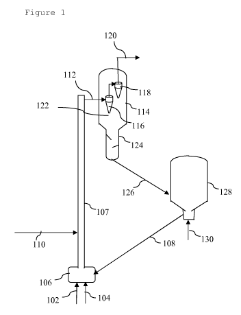
In figure 1 an embodiment according to the invention
is illustrated. In figure 1, a feed of solid biomass
material (102) and a steam feed (104) are both introduced
into the bottom (106) of an external reactor riser (107).
The external reactor riser (107) is located outside a
vessel and comprises a reactor riser pipe, which riser
reactor pipe has a curve or low velocity zone at its
upper end (in figure 1 a low velocity zone as illustrated
in figure 2A below is shown). In the bottom (106) of the
external reactor riser (107), the solid biomass material
(102) and the steam feed (104) are mixed with hot
regenerated catalytic cracking catalyst (108). The
mixture of catalytic cracking catalyst (108), solid
biomass material (102) and steam feed (104) is forwarded
into the external riser reactor (107). After about 0.1
seconds of residence time of the solid biomass material
(102) in the external reactor riser (107), a fluid
hydrocarbon feed (110) is introduced into the external
riser reactor (107). In the external reactor riser (107)
the solid biomass material (102) and the additional fluid
hydrocarbon feed (110) are catalytically cracked to
produce one or more cracked products. The mixture of one
or more cracked products, catalytic cracking catalyst,
steam, some residual non-cracked solid biomass material,
and possibly any non-cracked fluid hydrocarbon feed is
forwarded from the top of the external riser reactor
(107) via a crossover pipe (112) into a reactor vessel
CA 02833085 2013-10-11
WO 2012/143567 PCT/EP2012/057408
- 37 -
(114), comprising a first cyclone separator (116) and a
second cyclone separator (118). Cracked products (120)
are retrieved via the top of the second cyclone separator
(118) and optionally forwarded to a fractionator (not
shown). Spent catalytic cracking catalyst (122) is
retrieved from the bottom of the cyclone separators (116
and 118) and forwarded to a stripper (124) where further
cracked products are stripped off the spent catalytic
cracking catalyst (122).
The spent and stripped catalytic cracking catalyst (126)
is forwarded to a regenerator (128), where the spent
catalytic cracking catalyst is contacted with air (130)
to produce a hot regenerated catalytic cracking catalyst
(108) that can be recycled to the bottom (106) of the
reactor riser (107).
Figures 2A and 2B show schematic diagrams of
respectively specific embodiment A and specific
embodiment B for the process of figure 1, where
everything is as in the process as illustrated by figure
1, except that for figure 2B an external reactor riser is
used having a curved upper end.
Hence, figure 2A shows an external riser reactor
(207), comprising a riser reactor pipe with a so-called
"Blind Tee" (209A) at its upper end. The external riser
reactor (207) is connected via such "Blind Tee" (209A)
with a crossover pipe (212). The crossover pipe (212)
connects the external riser reactor (207) to a cyclone
(216) located in a vessel (214). In the "Blind Tee"
(209A) at the upper end of the reactor riser pipe, a
deposit (211) of catalytic cracking catalyst has formed,
forming an erosion resistant layer protecting the wall of
the external reactor riser (207).
CA 02833085 2013-10-11
WO 2012/143567 PCT/EP2012/057408
- 38 -
Figure 2B shows an external riser reactor (207),
comprising a riser reactor pipe with a curve (209B) at
its upper end. The external riser reactor (207) is
connected via such curve (209B) with crossover pipe
(212). In the curve (209B) at the upper end of the
reactor riser pipe, a deposit (211) of catalytic cracking
catalyst has formed, forming an erosion resistant layer
protecting the wall of the external reactor riser (207).
In figure 3 another embodiment according to the
invention is illustrated. In figure 3, wood parts (302)
are fed into a torrefaction unit (304), wherein the wood
is torrefied to produce torrefied wood (308) and gaseous
products (306) are obtained from the top. The torrefied
wood (308) is forwarded to a micronizer (310), wherein
the torrefied wood is micronized into micronized
torrefied wood (312). The micronized torrefied wood (312)
is fed directly into the bottom of an external fluidized
catalytic cracking (FCC) riser reactor (320) with a curve
or low velocity zone at its termination. In addition, a
long residue (316) is fed to the external FCC riser
reactor (320) at a position located downstream of the
entry of the micronized torrefied wood (312). In the FCC
riser reactor (320) the micronized torrefied wood (312)
is contacted with new and regenerated catalytic cracking
catalyst (322) in the presence of the long residue (316)
at a catalytic cracking temperature. A mixture of spent
catalytic cracking catalyst and produced cracked products
is separated in cyclone separators located in vessel
(326). The spent catalytic cracking catalyst (328) is
forwarded via stripper section (327) to regenerator
(330), where it is regenerated and recycled to the bottom
of the FCC riser reactor (320) as part of the regenerated
catalytic cracking catalyst (322). The cracked products
CA 02833085 2013-10-11
WO 2012/143567
PCT/EP2012/057408
- 39 -
(324) are forwarded to a fractionator (332). In the
fractionator (332) the cracked products (324) are
fractionated into several product fractions (334, 336,
338 and 340) including a gasoline containing fraction
(340). The gasoline containing fraction (340) is
forwarded to a hydrodeoxygenation reactor (342) where it
is hydrodeoxygenated over a sulphided Nickel-Molybdenum
on alumina catalyst to produce a hydrodeoxygenated
product (344). The hydrodeoxygenated product can be
blended with one or more additives to produce a biofuel
suitable for use in automotive engines.