Note: Descriptions are shown in the official language in which they were submitted.
CA 02833730 2013-11-19
MECHANIZED AND AUTOMATED WELL SERVICE RIG SYSTEM
CROSS-REFERENCE TO RELATED APPLICATIONS
[0001] This
application claims priority under 35 U.S.C. 119 to U.S. Provisional
Patent Application No. 61/728,156, titled "Automated Workover Rig System,"
filed on
November 19, 2012, the entirety of which is incorporated by reference herein.
[0002] The
present application is related also to United States Patent Application
Serial Number _______________________________________________________ ,
entitled "Mechanized and Automated Well Service Rig," filed
with the U.S. Patent and Trademark Office on November 19, 2013, and whose
entire
contents are hereby incorporated herein by reference.
[0003] The
present application is related also to United States Patent Application
Serial Number _______________________________________________________ ,
entitled "Mechanized and Automated Catwalk System," filed
with the U.S. Patent and Trademark Office on November 19, 2013, and whose
entire
contents are hereby incorporated herein by reference.
[0004] The
present application is related also to United States Patent Application
Serial Number _______________________________________________________ ,
entitled "Tong System for Tripping Rods and Tubulars," filed
with the U.S. Patent and Trademark Office on November 19, 2013, and whose
entire
contents are hereby incorporated herein by reference.
[0005] The
present application is related also to United States Patent Application
Serial Number _______________________________________________________ ,
entitled "Methods of Mechanized and Automated Tripping of
Rods and Tubulars," filed with the U.S. Patent and Trademark Office on
November 19,
2013, and whose entire contents are hereby incorporated herein by reference.
[0006] The
present application is related also to United States Patent Application
Serial Number _______________________________________________________ ,
entitled "Rod and Tubular Racking System," filed with the
U.S. Patent and Trademark Office on November 19, 2013, and whose entire
contents are
hereby incorporated herein by reference.
TECHNICAL FIELD
[0007] This
disclosure relates generally to well service systems and, more particularly,
to mechanized and automated well service rig systems for tripping rods and
tubulars.
CA 02833730 2013-11-19
BACKGROUND OF THE INVENTION
[0008] During the production life cycle of an oil well, a rod
string or tubular string
may need to be pulled out of hole or run into hole for various reasons. For
example, to
initiate controlled recovery, a tubular string is run down-hole to provide a
controlled
pathway for fluid resources to be brought from the well to the surface. A
sucker rod
string may also be run down-hole to actuate a pump installed within the well.
In some
cases, after a tubular string and/or a rod string is initially run down-hole,
the tubular
string and/or rod string may need to be pulled out of hole for repair or
maintenance of the
well or other down-hole equipment. Thus, the tubular string and/or rod string
are pulled
out of hole mid-production and then run back in after the necessary
maintenance is
completed. At the end of a wells production life, the tubular string and/or
rod string is
likewise pulled out of hole.
[0009] The processes of pulling a rod string or tubular string
out of a well and running
a rod string or tubular string into a well are examples of a class of
operations known as
tripping. Tripping operations typically require several large pieces of
equipment to
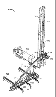
perform various aspects of the processes. For example, as a rod string or
tubular string is
_
pulled out of hole, the string segments, which are generally threaded together
at the ends
to form the string, are to be unthreaded from each other as they are lifted
out of hole.
Typically, a tong device is used to rotate a segment or coupling from the rest
of the string
to unthread the segment from the string. Conventionally, such task requires an
operator
to interface with the tong device or even to actuate the tong device. In
addition to
requiring operator interfacing for unthreading string segments, typical
tripping processes
and the equipment involved require a significant amount of human intervention.
[0010] Furthermore, many wells utilize both tubular and rods
down-hole. Thus, both
rod tripping processes and tubular tripping processes will need to be
performed for such
wells. However, rods are and tubulars require different handling. Thus,
generally,
different equipment is used to handle rods and tubulars. Specifically, rods,
which are
thinner and more fragile than tubulars require special handling to avoid
damage to the
rods. However, conventional tripping equipment and methods are generally not
suitable
for handling rods, and are not flexible between handling rods and handling
tubulars.
2
CA 02833730 2013-11-19
Typical tripping equipment also lacks a degree of flexibility, customizable
control, and
efficiency that could improve the cost, time, and operator experience of the
process.
SUMMARY
[0011] These and other aspects, features and embodiments of the invention
will
become apparent to a person of ordinary skill in the art upon consideration of
the
following detailed description of illustrated embodiments exemplifying the
best mode for
carrying out the invention as presently perceived.
[0012] According to an aspect of the present disclosure, A well service rig
system
includes a well service rig, a catwalk, and a tong system. The well service
rig includes a
rig base unit and a mast coupled to the rig base unit and movable between a
folded
position and an upright position. The well service rig further includes a
vertical guide
supported from the mast, and a traveling block system coupled to the vertical
guide
configured to travel at least a portion of the vertical guide. The catwalk
includes a unit
comprising a first end, a second end, a first side and a second side. The
catwalk further
includes a carriage disposed on the unit and movable between a horizontal
position, a
raised position, and a telescoping position. The catwalk further includes a
racking system
coupled to the unit and movable between a transport position and an
operational position.
In the transport position, the racking system is folded into the first and/or
second sides of
the unit. In the operational position, the racking system extends out from the
first and/or
second sides of the unit. The racking system is configured to store, feed, or
receive a
plurality tubulars and/or a plurality of rods. The tong system includes a
clamp or a slip =
configured to hold and support a rod or tubular string, respectively. The tong
system
further includes a tong assembly configured to hold and twist a first rod or
tubular in
relation to the rod or tubular string, threading or unthreading the first rod
or tubular to or
from the rod or tubular string.
[0013] According to an aspect of the present disclosure, a well service rig
system
includes a well service rig, a catwalk system, and a tong system. The well
service rig
includes a mast and a vertical guide supported from the mast. The well service
rig further
includes a traveling block system coupled to the vertical guide configured to
travel at
least a portion of the vertical guide, the traveling block system configured
to pick up and
3
CA 02833730 2013-11-19
raise or lower a rod or tubular. The catwalk includes a catwalk unit
configured to deliver
or receive the rod tubular to or from the traveling guide. The catwalk further
includes a
racking system coupled to the catwalk unit, the racking system configured to
store the rod
or tubular, feed the rod or tubular onto the catwalk unit, and/or receive the
tubular or the
rod from the catwalk unit. The tong system includes a clamp or a slip
configured to hold
and support a rod or tubular string, respectively. The tong system further
includes a tong
assembly configured to hold and twist the rod or tubular in relation to the
rod or tubular
string, threading or unthreading the rod or tubular to or from the rod or
tubular string.
[0014] According to an aspect of the present disclosure, a well service rig
system
includes a well service rig and a catwalk. The well service rig includes a rig
base unit, a
mast coupled to the rig base unit. The mast is movable between a folded
position and an
upright position. The well service rig further includes a vertical guide
supported from the
mast, and a traveling block system coupled to the vertical guide configured to
travel at
least a portion of the vertical guide. The catwalk further includes a unit
comprising a first
end, a second end, a first side and a second side. The catwalk further
includes a carriage
disposed on the unit and movable between a horizontal position, a raised
position, and a
telescoping position. The catwalk further includes a racking system coupled to
the unit
and movable between a transport position and an operational position. In the
transport
position, the racking system is folded into the first and/or second sides of
the unit. In the
operational position, the racking system extends out from the first and/or
second sides of
the unit. The racking system is configured to store, feed, or receive a
plurality tubulars
and/or a plurality of rods.
[0015] According to an aspect of the present disclosure, a well service rig
for tripping
rods and tubulars includes a service rig base unit, a mast coupled to the well
service rig
base unit movable between a folded position and an upright position, a
vertical guide
mounted to the mast, and a traveling block system coupled to the vertical
guide at a first
end and configured to travel up and down at least a portion of a length of the
vertical
guide. The traveling block system couplable to a rod, a tubular, or both at a
second end.
[0016] According to an aspect of the present disclosure, a vertical
tracking guide
includes a linear shaft suspended from a mast of a service rig. The linear
shaft is coupled
4
CA 02833730 2013-11-19
to a traveling block system, and the traveling block system configured to
travel at least a
portion of the linear shaft.
[0017] According to an aspect of the present disclosure, a service rig
traveling block
system includes a block guide configured to couple to and travel along a
vertical guide.
The traveling block system further includes a block body coupled to the block
guide. The
traveling block system further includes a rotating dial coupled to the block
body. The
traveling block system further includes a link tilt system comprising a
proximal end and a
distal end, the proximal end being coupled to the rotation dial, wherein the
rotation dial
rotates the link tilt system into a plurality of positions relative to the
block body. The
traveling block system also includes an elevator coupled to the distal end of
the link tilt
system and configured to pick up a rod or a tubular, respectively.
[0018] According to an aspect of the present disclosure, a catwalk system
includes a
unit having a first end, a second end, a first side, and a second side, in
which the first and
second sides extend from the first end to the second end, and the first side
is opposite the
second side. The catwalk system further includes a carriage disposed on the
unit and
coupled to the unit at the second end and extending towards the first end. The
carriage is
movable between a horizontal position and a sloped position, and between an
extended
position and a retracted position. The catwalk system farther includes a
racking system
coupled to the first side of the unit, the second side of the unit, or both.
The racking
system comprising a plurality of racking layers configured to store and
support a plurality
of rods and/or tubulars.
[0019] According to an aspect of the present disclosure, a catwalk system
includes a
unit having a first end, a second end, a first side, and a second side, in
which the first and
second sides extend from the first end to the second end, and the first side
is opposite the
second side. A carriage is disposed on the unit and coupled at the second end
and
extending towards the first end. The carriage is movable between a horizontal
position
and a sloped position and a telescoping position. The catwalk system further
includes a
racking system coupled to the first side of the unit, the second side of the
unit, or both.
The racking system comprising a plurality of base beams, each of the plurality
of base
beams comprising a coupling end and a distal end, and coupled to the unit at
the coupling
end. The plurality of base beams extend from the unit in the operational
position. The
CA 02833730 2013-11-19
plurality of base beams are configured to support a plurality of rods, a
plurality of
tubulars, or both. The racking system further includes a plurality of indexers
coupled to
the first, second, or both sides of the unit. Each of the plurality of
indexers comprises a
series of rotating holders configured to transport rods and tubulars between
the carriage
and the plurality of base beams. The racking system further includes a jack
coupled to
each of the plurality of base beams at a distal end opposite the unit in the
operational
position. The jack is configured to raise or lower the distal end of the base
beam relative
to the coupling end.
[0020] According to an aspect of the present disclosure, a catwalk system
includes a
unit having a first end, a second end, a first side, and a second side. The
first and second
sides extend from the first end to the second end, and the first side is
opposite the second
side. The catwalk system further includes a carriage disposed on the unit and
coupled at
the second end and extending towards the first end. The carriage is movable
between a
horizontal position and a sloped and telescoping position. The catwalk system
further
includes a racking system coupled to the first side of the unit, the second
side of the unit,
or both. The racking system is configured to store, feed, and/or receive a
plurality of
tubulars and/or rods. The racking system is movable between a transport
position in
which the racking system is folded along the first, second, or both sides of
the unit and an
operational position in which the racking system extends outwardly from the
first,
second, or both sides of the unit.
[0021] According to an aspect of the present disclosure, a racking system
includes a
rack comprising a plurality of beams configured to support a plurality of
rods, a plurality
of tubulars, or both, each of the plurality of beams comprising a proximal end
and a distal
end. The racking system further includes a plurality of indexers aligned with
or proximal
to the proximal ends of the plurality of base beams, wherein each of the
plurality of
indexers comprises a series of rotating holders configured to transport the
plurality of
rods, tubulars, or both to and from the rack. Additionally, the racking system
further
includes a jack coupled to the distal end each of the plurality of base beams,
wherein the
jack raises and lowers the distal end of the base beam in relation to the
proximal end.
[0022] According to an aspect of the present disclosure, a method of
receiving and
storing a plurality of rods or tubulars includes receiving a rod or tubular
onto a rotating
6
CA 02833730 2013-11-19
holder of an indexer, and rotating the indexer and transporting the rod or
tubular from a
first side of the indexer to a second side of the indexer, the second side
opposite the first
side. The method further includes discharging the rod or tubular onto a rack
disposed
adjacent the second side of the indexer, the rack comprising a plurality of
base beams,
wherein each of the plurality of base beams comprised a proximal end. The
method
further includes receiving the rod or tubular onto the rack.
[0023] According to an aspect of the present disclosure, a method of
delivering a
plurality of rods or tubulars includes delivering a rod or tubular onto a
holder of an
indexer from a rack, and rotating the indexer and transporting the rod or
tubular from a
second side of the indexer to a first side of the indexer, the second side
opposite the first
side. The method further includes discharging the rod or tubular from the
indexer onto a
receiving device on the first side of the indexer.
[0024] According to an aspect of the present disclosure, a tong system for
handling
rods includes a base and a rod clamp disposed on the base. The rod clamp
comprising a
first clamp block and a second clamp block opposite the first clamp block. The
first
clamp block comprises a first clamp piston and a first clamp die disposed at a
distal end
of the first clamp piston. Likewise, the second clamp block comprises a second
clamp
piston and a second clamp die disposed at a distal end of the second clamp
piston. The
first and second clamp dies face each other. The tong system for handling rods
further
includes a rod positioner assembly coupled above the rod clamp via at least
one hydraulic
cylinder, the rod positioner configured to position and hold a rod via an
opening formed
therein. The tong system for handling rods further includes a tong assembly.
The tong
assembly is disposed on the base via a riser and a horizontal track, the tong
assembly
comprising a rod handling tong and a lower centralizer guide positioned above
the rod
handling tong. The tong system for handling rods also includes a centralizer
arm
extending from the base to a height above the lower centralizer guide. The
centralizer
arm further comprises a guide member.
[0025] According to an aspect of the present disclosure, a tong system for
handling
tubulars includes a base and a tubing slip disposed above the base. The tubing
slip is
configured to receive a tubular therethrough. The tong system for handling
tubulars
further includes a tong assembly disposed on the base via a riser and a
horizontal track.
7
CA 02833730 2013-11-19
The tong assembly includes a tubular handling tong configured to engage and
thread or
unthread the tubular to or from a tubular string. The tong assembly further
includes a
tubular backup and a lower centralizer guide positioned above the tubular
handling tong.
The tong system also includes a centralizer arm extending from the base to a
height
above the lower centralizer guide, the centralizer arm comprising a guide
member.
[0026] According to an aspect of the present disclosure, a method of
pulling a rod out
of a well hole includes lifting a rod string through a disengaged rod
positioner with a
traveling block system until a junction between a first rod of the rod string
and a second
rod of the rod string is above the rod positioner. The method also includes
engaging the
rod positioner onto the second rod, wherein the rod positioner holds the
second rod in a
stationary position, and suspending the rod string in the rod positioner. The
method
further includes engaging a tong assembly onto the first rod, wherein the tong
assembly
twists the first rod and unthreads the first rod from the second rod. Then the
method
includes disengaging the tong assembly from the first rod, and lowering and
placing the
first rod onto a carriage, wherein the carriage is raised at an angle. The
method further
includes releasing the first rod from the traveling block system and lowering
the carriage
into a horizontal position. The method also includes tilting the carriage and
discharging
the rod from the carriage onto a rod racking system.
[0027] According to an aspect of the present disclosure, a method of
pulling a tubular
out of a well hole includes lifting a tubular string through a disengaged
tubing slip with a
traveling block system until a junction between a first tubular of the tubular
string and a
second tubular of the tubular string is above the tubing slip. The method
further includes
engaging the tubing slip onto the second tubular of the tubular string,
wherein the tubing
slip holds the second tubular in a stationary position, and suspending the
tubular string
from the tubing slip. The method also includes engaging a tong assembly onto
the first
tubular, wherein the tong assembly twists the first tubular and unthreads the
first tubular
from the second tubular. The method also includes disengaging the tong
assembly from
the first tubular, and lowering and placing the first tubular onto a carriage,
wherein the
carriage is raised at an angle. The method further includes lowering the
carriage into a
horizontal position, tilting the carriage, and discharging the tubular from
the carriage onto
a tubular racking system.
8
CA 02833730 2013-11-19
[0028] According to an aspect of the present disclosure, a method of running a
rod
into a well hole includes delivering a first rod from a rod racking system
onto a carriage
via an indexer, and raising the carriage from a horizontal position into a
sloped and
extended or telescoped position. The method also includes engaging a traveling
block
system with the first rod via a rod elevator of a traveling block system,
lifting the first rod
from the carriage, and suspending the first rod from the traveling block
system above a
tong system. The tong system comprises a tong assembly, an upper centralizer,
a lower
centralizer, a rod positioner, and a rod clamp, the upper centralizer aligning
the first rod
with the lower centralizer. The method also includes suspending a rod string
by the rod
positioner, and engaging a rod flat backup onto one or more rod flats of the
rod string.
The method further includes lowering the first rod through the lower
centralizer of the
tong assembly onto the rod string, and engaging the tong assembly onto the
first rod and
threading the first rod onto the rod string.
[0029] According to an aspect of the present disclosure, a method of
running a tubular
into a well hole includes delivering a first tubular from a tubular racking
system onto a
carriage via an indexer. The method also includes raising the carriage from a
horizontal
position into a sloped and telescoped position. The method also includes
engaging the
first tubular to a tubular elevator of a traveling block system, lifting the
first tubular from
the carriage, and suspending the first tubular from the traveling block system
above a
tong system. The tong system comprises a tong assembly, an upper centralizer,
a lower
centralizer, and a tubing slip, the upper centralizer aligning the first
tubular with the
lower centralizer. The method further includes suspending a tubular string
from an
engaged tubing slip. The method also includes lowering the first tubular
through the
lower centralizer and onto the tubular string, engaging the tong assembly onto
the first
tubular, and threading the first tubular onto the tubular string.
BRIEF DESCRIPTION OF THE DRAWINGS
[0030] For a more complete understanding of the claimed invention and the
advantages thereof, reference is now made to the following description, in
conjunction
with the accompanying figures briefly described as follows. In the drawings,
reference
numerals designate like or corresponding, but not necessarily identical,
elements. The
9
CA 02833730 2013-11-19
drawings illustrate only example embodiments of methods, systems, and devices
for
carrying out a class of operations known as tripping and are therefore not to
be
considered limiting of its scope, such method, systems, and device may admit
to other
equally effective embodiments that fall within the scope of the present
disclosure. The
elements and features shown in the drawings are not necessarily to scale,
emphasis
instead being placed upon clearly illustrating the principles of the example
embodiments.
Additionally, certain dimensions or positionings may be exaggerated to help
visually
convey such principles. The methods shown in the drawings illustrate certain
steps for
carrying out the techniques of this disclosure. However, the methods may
include more
or less steps than explicitly illustrated in the example embodiments. Two or
more of the
illustrated steps may be combined into one step or performed in an alternate
order.
Moreover, one or more steps in the illustrated methods may be replaced by one
or more
equivalent steps known in the art to be interchangeable with the illustrated
step(s). In one
or more embodiments, one or more of the features shown in each of the figures
may be
omitted, added, repeated, and/or substituted. Accordingly, embodiments of the
present
disclosure should not be limited to the specific arrangements of components
shown in
these figures.
[0031] Figure 1 illustrates a perspective view of a well service rig
system, in
accordance with certain example embodiments;
[0032] Figure 2 illustrates a detailed view of a work floor of the well
service rig
system, in accordance with certain example embodiments;
[0033] Figure 3a illustrates a top view of the well service rig system in a
135
orientation, in accordance with certain example embodiments;
[0034] Figure 3b illustrates a top view of the well service rig system in a
90
orientation, in accordance with certain example embodiments, in accordance
with certain
example embodiments;
[0035] Figure 4 illustrates a side view the well service rig in a folded or
transport
position, in accordance with certain example embodiments;
[0036] Figure 5a illustrates a side view of the well service rig in a
raised position with
the work floor in a base position, in accordance with certain example
embodiments;
CA 02833730 2013-11-19
[0037] Figure 5b illustrates a rear view of the well service rig in the
raised position
with the work floor in the base position, in accordance with certain example
embodiments;
[0038] Figure 6a illustrates a side view of the well service rig in a
raised position with
the work floor at raised height, in accordance with certain example
embodiments;
[0039] Figure 6b illustrates a rear view of the well service rig in the
raised position
with the work floor at a raised height, in accordance with certain example
embodiments;
[0040] Figure 7 illustrates a detailed perspective view of the work floor,
in accordance
with certain example embodiments;
[0041] Figure 8a illustrates a rod servicing traveling block system, in
accordance with
certain example embodiments;
[0042] Figure 8b illustrates a detailed view of detail 8b of Figure 8, in
accordance
with certain example embodiments;
[0043] Figure 9a illustrates a tubular servicing traveling block system, in
accordance
with certain example embodiments;
[0044] Figure 9b illustrates a detailed view of detail 9b of Figure 9, in
accordance
with certain example embodiments;
[0045] Figure 10 illustrates a top view of a catwalk in a horizontal
position, in
accordance with certain example embodiments;
[0046] Figure 11 illustrates a side view of the catwalk in the horizontal
position, in
accordance with certain example embodiments;
[0047] Figure 12 illustrates a detailed view of a skate, in accordance with
example
embodiments;
[0048] Figure 13 illustrates a side view of the catwalk in a raised and
extended
position, in accordance with certain example embodiments;
[0049] Figure 14 illustrates a perspective view of the catwalk in a raised
and extended
position, in accordance with certain example embodiments;
[0050] Figure 15 illustrates an interaction between a racking system and
the catwalk
during a running into hole operation, in accordance with certain example
embodiments.
11
CA 02833730 2013-11-19
[0051] Figure 16 illustrates the interaction between the racking system and
the
catwalk during a pulling out of hole operation, in accordance with certain
example
embodiments;
[0052] Figure 17 illustrates a rod tong system in a disengaged positionõ in
accordance
with certain example embodiments;
[0053] Figure 18 illustrates the rod tong system in an engaged position, in
accordance
with certain example embodiments;
[0054] Figure 19 illustrates the rod tong system in a transfer position, in
accordance
with certain example embodiments;
[0055] Figure 20 illustrates a front view of a rod clamp and rod positioner
assembly,
in accordance with certain example embodiments;
[0056] Figure 21 illustrates a perspective view of a rod clamp and rod
positioner
assembly, in accordance with certain example embodiments;
[0057] Figure 22 illustrates an exploded view of a clamp block of the rod
clamp, in
accordance with certain example embodiments;
[0058] Figure 23a illustrates a top view of a rod coupling clamp in an open
position,
in accordance with certain example embodiments;
[0059] Figure 23b illustrates a top view of the rod coupling clamp in a
closed position,
in accordance with certain example embodiments;
[0060] Figure 24a illustrates a top view of a rod flat clamp in an open
position, in
accordance with certain example embodiments of the present disclosure;
[0061] Figure 24b illustrates a top view of the rod flat clamp in a closed
position, in
accordance with certain example embodiments;
[0062] Figure 25a illustrates a top view of a rod positioner in an open
position, in
accordance with certain example embodiments of the present disclosure;
[0063] Figure 25b illustrates a top view of the rod positioner in a closed
position, in
accordance with example embodiments;
[0064] Figure 26 illustrates a detailed perspective view of a portion of a
rod tong, in
accordance with certain example embodiments;
[0065] Figure 27 illustrates a detailed view of a jaw assembly featuring a
notched jaw
die, in accordance with certain example embodiments;
12
CA 02833730 2013-11-19
[0066] Figure 28 illustrates a detailed view of a jaw assembly featuring a
flat jaw die,
in accordance with certain example embodiments;
[0067] Figure 29 illustrates a tubular tong system, in accordance with
certain example
embodiments of the present disclosure;
[0068] Figure 30 illustrates an automation control panel for controlling
certain aspects
of the well service rig system, in accordance with certain example embodiments
of the
present disclosure;
[0069] Figure 31 illustrates a manual control panel for controlling certain
aspects of
the well service rig system, in accordance with certain example embodiments of
the
present disclosure;
[0070] Figure 32 is a flow chart illustrating a method of pulling a rod out
of a well
hole, also known as a rod POH process, in accordance with example embodiments
of the
present disclosure;
[0071] Figure 33 is a flow chart illustrating a method of pulling a tubular
out of a well
hole, also known as a tubular POH process, in accordance with example
embodiments of
the present disclosure;
[0072] Figure 34 is a flow chart illustrating a method of running a rod
into a well hole,
also known as a rod RIH process, in accordance with example embodiments of the
present disclosure; and
[0073] Figure 35 is a flow chart illustrating a method of running tubulars
into a well
hole, also known as a tubular RIH process, in accordance with example
embodiments of
the present disclosure.
DETAILED DESCRIPTION OF THE EXAMPLE EMBODIMENTS
[0074] In the following detailed description of the example embodiments,
numerous
specific details are set forth in order to provide a more thorough
understanding of the
disclosure herein. However, it will be apparent to one of ordinary skill the
art that the
example embodiments herein may be practiced without these specific details. In
other
instances, well-known features have not been described in detail to avoid
unnecessarily
complicating the description. As used herein, a length, a width, and a height
can each
= generally be described as lateral directions.
13
CA 02833730 2013-11-19
[0075] Designations such as "first", "second", and "third" are merely used
to call out
distinct features rather than a total number of items. Descriptions such as
"top",
"bottom", "distal", and "proximal" are meant to describe different portions of
an element
or component and are not meant to imply an absolute orientation. Furthermore,
descriptions such as "above-, "below", "to the side of', and "adjacent to" are
meant to
describe a special relationship between two items and are not meant to imply
absolute
orientation. For example, a third item can be disposed between the two items
to which
the above language refers.
[0076] Example embodiments of the claimed invention are directed to a well
service
rig system for tripping rods and tubulars. As used herein, "rods" and -
tubulars" are not
meant to limit the scope to a specific type of item referred to in the
industry as a "rod" or
a "tubular", but rather include a host of items that could be considered a rod
or a tubular
by the broadest sense of the word. For example a rod could include a sucker
rod, but it
may also include other items that could be classified as a rod by the broadest
definition of
the term "rod".
[0077] Example embodiments of the claimed intervention make reference to
example
processes such a pulling rods out of hole, running rods into hole, pulling
tubulars out of
hole, and running tubulars into hole. However, the techniques presented herein
are also
applied to other tripping processes used in the industry that may or may not
involve rods
or tubulars. Furthermore, the techniques presented herein also apply to
processes not
commonly known as tripping but which employ certain similar principles which
can be
effectively carried out by certain aspects of the present disclosure.
[0078] Turning to the figures, Figure 1 illustrates a well service rig
system 100, in
accordance with example embodiments of the present disclosure. Figure 2
illustrates a
detailed view of region A of Figure 1. Referring to Figures 1 and 2, the well
service rig
system 100 includes a well service rig 102, a catwalk 104, a racking system
106, and a
tong system 108. Among other components, the well service rig 102 includes a
mast 110,
a vertical guide 112, a traveling block system 114, and a work floor 116. The
traveling
block system 114 is configured to pick up and lower or raise a rod or tubular.
In certain
example embodiments, the vertical guide 112 hangs from the mast 110 and the
traveling
block system travels up and down the vertical guide 112 as it lowers or raises
a rod or
14
CA 02833730 2013-11-19
tubular. In certain example embodiments, the work floor 116 is coupled to the
mast 110
and provides a work surface for operators or other equipment, if needed.
[0079] Among
other components, the catwalk 104 includes a carriage 118 which can
be raised from a horizontal position to a sloped and telescoped position.
Figure 1
illustrates the carriage 118 in the sloped and telescoped position. The
carriage 118 is
configured to deliver or receive a rod or tubular between the racking system
106 and the
traveling block system 114. When the carriage is in the sloped position and
telescoped,
the carriage 118 is extended and the first end 120 of the carriage 118 is
raised and reaches
towards the work floor 116. For example, in a pulling out of hole (POH)
operation, in the
sloped and telescoped position, the carriage 118 is ready to receive a rod or
tubular from
the traveling block system 114. After the rod or tubular is placed onto the
carriage 118,
the carriage is lowered and retracted into the horizontal position and the rod
or tubular is
transferred to the racking system 106. In certain example embodiments, in a
running into
hole (RIH) operation, a rod or tubular is transferred from the racking system
106 to the
carriage 118 in the horizontal position. The carriage 118 is then raised into
the sloped
position and extended into the telescoped position with the rod or tubular on
board, and
the traveling block system 114 picks up the rod or tubular from the first end
120 of the
carriage 118.
[0080] Among other components, the racking system 106 includes a plurality of
stackable beams 122. In a POH operation, the beams 122 support and store the
rods or
tubulars when the rods or tubulars are delivered from the carriage 118. In a
RIH
operation, the beams 122 deliver the rods or tubulars onto the carriage 118.
In certain
example embodiments, the beams 122 are layered and thus can support and store
a
plurality of layers of rods and tubulars. In certain example embodiments, and
as
illustrated in Figure 1, the beams 122 are coupled to either side of the
catwalk 104.
[0081] Among other components, the tong system 108 includes a tong assembly
124
and at least one string gripping device 126. In the embodiment illustrated in
Figure 2, the
string gripping device 126 is a tubing slip configured to hold a tubular
string for at least a
portion of the time. In other example embodiments, the tubing slip is replaced
with a rod
clamp (Figure 22) configured to hold a rod string. In the present disclosure,
string
gripping device 126 refers to either a tubing slip or a rod clamp, or other
functionally
CA 02833730 2013-11-19
similar devices. The tong assembly 124 is configured to unthread a first rod
or tubular of
a rod or tubular string from the rest of the rod or tubular string. For
example, in a POH
operation for sucker rods, the traveling block system 104 pulls a sucker rod
string to a
distance above ground such that a first sucker rod of the sucker rod string is
completely
above ground. The tong system 108 engages the junction between the first
sucker rod
and the rest of the sucker rod string. The string gripping device 126 holds
onto the rest of
the sucker rod string while the tong assembly 124 unthreads the first sucker
rod from the
rest of the sucker rod string. After the first sucker rod is separated from
the rest of the
sucker rod string, the first sucker rod is supported by and suspended from the
traveling
block system, and the rest of the sucker rod string is supported by the string
gripping
device 126. The first sucker rod is then placed on the carriage 104 in the
sloped position
and delivered to the racking system 106 for storage. In certain example
embodiments,
the well service rig system 100 is configured to perform a plurality of
tripping services,
including but not limited to POH and RIH operations, for a plurality of rod
and tubular
types. The components of the well service rig system 100 and their functions
and
interactions, further embodiments, as well as other example methods of use,
will be
discussed in further detail in this disclosure.
[0082] In
certain example embodiments, the configuration or arrangement of the well
service rig system 100 is adaptable to fit the needs of the field and/or well.
Figures 3a
and 3b illustrate two example arrangements of the catwalk 104 in relation to
the well
service rig 102, in accordance to example embodiments of the disclosure.
Referring to
Figure 3a, in certain example embodiments, the catwalk 104 is placed at a 135
angle
with respect to the well service rig 102. Referring to Figure 3b, in certain
example
embodiments, the catwalk 104 is placed at a 90 angle with respect to the well
service rig
102. In certain example embodiments, the catwalk 104 can be placed at any
angle with
respect to the well service rig 102. Placement of the catwalk 104 with respect
to the well
service rig 102 can depend on various factors, such as space limitation,
placement of
other equipment, or preference. In certain example embodiments, one or more of
these
components are replaced with a different component or removed from the well
service rig
system 100.
16
CA 02833730 2013-11-19
[0083] Each of the well service rig 102, the catwalk 104, the racking
system 106, and
the tong system 108 will now be described in detail. Figure 4 illustrates a
side view the
well service rig 102 in a folded or transport position, in accordance with
example
embodiments of the present disclosure. Referring to Figure 4, in addition to
the mast
110, the vertical guide 112, the traveling block system 114, and the work
floor 116, the
well service rig 102 further includes a base unit 402 which provides a support
for and
houses the mast 110 and work floor 116. In certain example embodiments, and as
illustrated in Figure 4, the base unit 402 is a transport vehicle 404, and
comprises a
plurality of wheels 406. In such an embodiment, the well service rig 102 is
independently mobile and can be driven to and from the work site when in the
folded or
transport position. In certain other example embodiments, the base unit 402 of
the well
service rig 102 is a skid rather than a vehicle. The base unit 402 includes a
first end 408
and a second end 410. The mast 110 is coupled to the second end 410 of the
base unit
402 via a hinge 412 or functionally hinging device. Thus the mast 110 is
movable from
the folded position into a raised position (Figures 5a-6b) via the hinge. In
the folded
position, the mast 110 is in a horizontal position oriented along the base
unit 402. The
work floor 116 is likewise folded onto the base unit 402. The well service rig
102 is
transportable in the folded position.
[0084] Figure 5a illustrates a side view of the well service rig 102 in a
raised position
with the work floor 116 in a base position, in accordance with example
embodiments of
the present disclosure. Figure 5b illustrates a rear view of the well service
rig 102 in the
raised position with the work floor 116 in the base position, in accordance
with example
embodiments of the present disclosure. Referring to Figures 5a and 5b, in the
raised
position, the mast 110 of the well service rig 102 is unfolded from the base
unit 402 via
the hinge 412 such that the mast 110 stands vertically from the second end 404
of the
well service rig 102. In certain example embodiments, the mast 110 stands at
an angle
offset to the vertical, as illustrated in Figure 5a. In certain example
embodiment, the
vertical is defined as being perpendicular to the ground or parallel to the
direction of the
well hole. For example, in one or more embodiments, the mast 110 is offset to
the
vertical by 4.5 . In certain other examples, the mast 110 is offset to the
vertical by more
or less than 4.5 , depending on the field and well properties, space
limitations, mast
17
CA 02833730 2013-11-19
certification, etc. In certain example embodiments, the mast 110 is parallel
to the
vertical.
[0085] The mast 110 includes a top end 502 which is the highest portion of the
mast
110. In certain example embodiments, the mast 110 has an adjustable (i.e.,
telescoping)
height. In such an embodiment, the mast 110 includes a base portion 508 and an
extendable portion 506. The base portion 508 and the extendable portion 506
are coupled
by a brace 504 or mechanical lock, which keeps the extended portion stable and
aligned
with the base portion 508. Accordingly, the mast 110 can be configured into an
extended
position and a retracted position. In the extended position, the extendable
portion 506
extends from the base portion 508 and adds to the height of the base portion
508. In the
retracted position, the extendable portion 506 is retracted within the base
portion 508.
The mast 110 is in the retracted position when the well service rig 102 is in
the transport
position, as shown in Figure 4, and extended when the well service rig 102 is
in the
operating position. In certain other example embodiments, the mast 110 is a
non-
telescoping single height structure. The offset of the mast 110 to the
vertical allows the
well rig 102 to be parked to the side of a well hole and the top end 502 of
the mast to be
directly over the well hole. However, in certain other example embodiments,
the mast is
disposed vertically without an offset.
[0086] In
certain example embodiments, the vertical guide 112 is coupled to and
supported by the mast 110. The vertical guide 112 includes a top end 510 and a
bottom
end 512. In certain example embodiments, the top end 510 of the vertical guide
112 is
coupled to the top end 502 of the mast 110. In certain example embodiments,
the top end
510 of the vertical guide 112 is coupled to the top end 502 of the mast 110
via a hinge
516. In certain other example embodiments, the vertical guide 112 is coupled
to the mast
110 via another coupling mechanism 512 which provides a certain amount of
angular
motion between the vertical guide 112 and the mast 110. In certain example
embodiments, the vertical guide 112 is further coupled to the mast 110 at the
bottom end
512 of the vertical guide 112. In certain such embodiments, the bottom end 512
of the
vertical guide 112 is coupled to the mast 110 via an extension bar 514. The
extension bar
514 is rotatively coupled to the mast at one end and rotatively coupled to the
vertical
guide 112 at another end, and holds the bottom end 512 of the vertical guide
112 in place
18
CA 02833730 2013-11-19
relative to the mast. Thus, the extension bar 514 provides both stability as
well a range of
motion for the vertical guide 112 with respect to the mast 110. In certain
other
embodiments, the extension bar 514 is coupled to the vertical guide 112 at a
point
between the top end 510 and the bottom end 512. In certain embodiments, the
extension
bar is removed or replaced with a different component which likewise provides
stability
as well as a range of motion for the vertical guide 112. In certain example
embodiments,
the vertical guide 112 is adjustable with respect to the mast 110, with the
coupling of the
top end 510 of the vertical guide 112 and the top end 502 of the mast 110
being the axis
of rotation, and the length of the extension bar 514 defining a maximum offset
between
the vertical guide 112 and the mast 110. In certain example embodiments, the
vertical
guide 112 is parallel to the vertical and parallel with a rod or tubular
string in a well. In
certain example embodiments, the vertical guide 112 is a shaft. The vertical
guide can
also be tubular, square, another generally linear configuration. In certain
example
embodiments, the vertical guide 112 is also telescoping and has an adjustable
length. In
certain example embodiments, the vertical guide 112 is folded into the mast
110 when the
well service rig is in the transport position, as shown in Figure 4.
[0087] The
traveling block system 114 is coupled to the vertical guide 112. In certain
example embodiments, the traveling block system 114 is coupled to the vertical
guide
112 via a releasable coupling mechanism such as a quick release mechanism,
such that
the traveling block system 114 can be easily coupled to and decoupled from the
vertical
guide 112. The traveling block system 114 is configured to travel up and down
the
vertical guide 112. In certain example embodiments, the traveling block system
114
travels at least a portion of the length of the vertical guide 112. The
traveling block
system 114 can travel more or less of a portion of the vertical guide 112
depending on the
motion needed for the operation as well as the configuration of the vertical
guide 112.
The traveling block system 114 is configured to pick up, raise, and/or lower
one or more
rods or tubulars. For example, in a POH operation, the traveling block system
114 is
configured to pick up and raise the first rod or tubular of a rod or tubular
string from the
well, and then lower the first rod or tubular onto the carriage 118 of the
catwalk 104. In a
RIH operation, the traveling block system 114 is configured to pick up and
raise a rod or
tubular from the carriage 118 and lower the rod or tubular onto a rod or
tubular string,
19
CA 02833730 2013-11-19
and then lower the rod or tubular string further down-hole. Thus, the
traveling block
system 114 is to be aligned with the rod or tubular string over the course of
travel. The
vertical guide 112 provides such an aligned path of travel for the traveling
block system
114. The traveling block system 114 is discussed in further detail below with
respect to
Figures 8a-9b.
[0088] In certain example embodiments, the work floor 116 of the well
service rig 102
can be adjusted from a base height to a variable second height. Figures 5a and
5b show
the work floor 116 at the base height. Figures 6a and 6b illustrate the well
service rig 102
with the work floor 116 raised to a second height. In certain example
embodiments, the
base height of the work floor 116 is 4 feet from the ground and second height
of the work
floor 116 is 20 feet from the ground. In certain other embodiments, the base
height is
lower than 4 feet, and in certain example embodiments, the second height is
between 4
feet and 20 feet, or greater than 20 feet. The height or position of the work
floor 116 is
typically chosen based on the height of the wellhead and other accessories.
Figure 7
illustrates a detailed perspective view of the work floor 116, shown here at
the base
height, in accordance with example embodiments of the present disclosure.
Referring to
Figure 7, the work floor 116 includes a surface 702 for supporting an operator
or other
equipment. The work floor 116 further includes an opening (not shown) through
which
the tong system 108 can be coupled to a wellhead and/or accessories. It should
be noted
that in certain example embodiments, the tong system 108 is attached and
supported from
the wellhead and/or accessories rather than from the work floor 116. In
certain example
embodiments, the work floor 116 is suspended from the mast 110 via a bracket
704.
Furthermore, the base portion 508 of the unit 102 includes a mounting 706
which
includes a column of receivers for coupling the work floor 116 to the mast 110
at
different heights along a portion of the mast 110, thereby providing a range
of heights for
the work floor 116.
[0089] Figure 8a illustrates one example embodiment of the traveling block
system
114 in a rod servicing configuration, in accordance with example embodiments
of the
present disclosure. Specifically, Figure 8a illustrates a rod servicing
traveling block
system 800. Figure 8b illustrates a detailed view of detail 8b of Figure 8a,
in accordance
with example embodiments of the present disclosure. Referring to Figures 8a
and 8b, the
CA 02833730 2013-11-19
traveling block system 800 includes a guide assembly 802, a block body 804, a
rotation
dial 806, one or more links 808, a link tilt actuator 810, and a rod elevator
812. The
guide assembly 802 couples the traveling block system 114 to the vertical
guide 112 and
travels up and down the vertical guide 112. In certain example embodiments,
the guide
assembly 802 includes a guide grip 832, which is disposed around the vertical
guide 112.
In certain example embodiments, the guide assembly 802 includes a quick
release
mechanism and can be easily coupled to and decoupled from the vertical guide
112. The
guide assembly 802 is coupled to the block body 804. The block body 804 drives
the
traveling block system 114 up and down the vertical guide 112 and actuates
other
mechanized aspects of the traveling block system 114. In certain example
embodiments,
the rotation dial 806 is coupled under the drive block 804 and above the one
or more
links 808. In certain example embodiments, the rotation dial 806 can be
rotated to
change the orientation of the links 808 and therefore the orientation of the
rod elevator
812. As discussed with reference to Figures 3a and 3b, the well service rig
system 100
allows the catwalk 104 to be oriented at any angle with respect to the well
service rig
102. As such, the traveling block system 800 may need to be able to pick up
and deliver
rods in a range of angles. The rotation dial 806 allows the links 808 and the
rod elevator
812 to be rotated to the appropriate angle for picking up and delivering rods
according to
the given angle of the catwalk 104 with respect to the well service rig 102.
In certain
example embodiment, the rotation dial 806 includes a plurality of holes which
can be
pinned to stabilize the rotation dial 806 in the desired position. In an
example
embodiment, the rotation dial 806 is positionable in 36 rotational positions.
[0090] In
certain example embodiments, the links 808 and the link tilt actuator 810 are
coupled to the rotation disk 806 opposite the block body 804 via a link holder
814. The
rotation disk 806, the links 808, the link tilt actuator 810, and the link
holder 814 are
jointly known as a link tilt system. In certain example embodiments, and as
shown in
Figure 8a, the traveling block system 800 includes a pair of links 808. Each
of the links
808 includes an block connector 816 disposed at one end and an elevator
connector 818
disposed at an opposite end, and a shaft 820 in between. The block connector
816
couples the links 808 to the link holder 814 with a degree of swinging or
tilting motion.
Specifically, in certain example embodiments, the block connectors 816 of the
links 808
21
CA 02833730 2013-11-19
are linked with the link holder 814 such that the links 808 can tilt in the
same direction
with respect to the link holder 814.
[0091] Each link 808 is coupled to one of the link tilt actuators 810. The
link tilt
actuators 810 are coupled to the link holder 814 at one end and coupled to the
shaft 820
of the respective link 808 at the opposite end. In certain example
embodiments, the link
tilt actuators 810 are configured to control tilting of the links 808 by
lifting or pushing the
links 808. In certain example embodiments, the link tilt actuators 810 each
include an
extender 830. The extenders 830 allow the link tilt actuators 810 to extend in
length and
push the links 808. Thus, in such example embodiments, when the extenders 830
are in a
neutral position, the links 808 are in a neutral position as well, hanging
from the link
holder 814. The links 808 are tilted or pushed when the extenders 830 are in
an extended
position. For example, in a RIH operation, the traveling block system 800 is
configured
to pick up a rod from the carriage 118. When the rod is in the carriage 118,
the rod is at
an angle to the traveling block system 800 and disposed at a distance away
from the
traveling block system. Thus, in order to align the rod elevator 812 with the
rod and
reach the rod, the link tilt actuators 810 push the links 808 toward the rod
to place the rod
elevator 812 at an appropriate angle and distance to reach and grip the rod.
In another
example, such as in an POH operation, the traveling block system 800 is
configured to
pick up a rod of a rod string positioned directly below the traveling block
system (i.e., in
the wellhole). The rod elevator 812 can grip the rod while in the neutral
position.
[0092] The elevator connectors 818 are coupled to the rod elevator 812.
Specifically,
the rod elevator 812 is coupled to and in between the elevator connectors 818
of the two
links 808. In certain example embodiments, the rod elevator 812 is rotatively
coupled in
between the elevator connectors 818 such that the rod elevator 812 can tilt
with respect to
the links 808. In certain example embodiments, the rod elevator 812 includes a
tiling
cylinder 822, which actuates the tilting of the rod elevator 812. In certain
example
embodiments, the rod elevator 812 is configured to couple to an end of a rod,
allowing
the traveling block system 800 to lift the rod. In certain example
embodiments, the rod
elevator 812 includes a clamp 826 having a middle orifice 828. In such
embodiments,
the rod elevator 812 opens to dispose the clamp 826 around the end of a rod
and closes to
retain the rod within the middle orifice 828. The clamp 826 then opens to
release the rod.
22
CA 02833730 2013-11-19
In certain example embodiments, the rod elevator 812 includes an open/close
cylinder,
which actuates opening and closing of the clamp 826.
[0093] The traveling block system 800 in conjunction with the rod elevator
812 is able
to pick up a rod from a rod string and deliver the rod onto a sloped carriage
118 in a POH
operation. Specifically, in a POH operation, the links 808 and the rod
elevator 812 are in
the neutral position when lifting a first rod of a rod string up and out of
the well hole.
After the tong system 108 unthreads the first rod from the rod string, the
bottom end of
the first rod is pushed at an angle onto the carriage 118, in which the first
rod is now at an
angle. Accordingly, the rod elevator, which is still gripping the first rod,
tilts with respect
to the links 808 to accommodate the angle of the first rod. As the traveling
block system
800 lowers the first rod further onto the carriage 118, the angle of the first
rod to the
vertical increases. Thus, the tilting angle of the rod elevator 812 increases
accordingly.
As the first rod is almost completely disposed on the carriage 118, the links
808 are push
or tilted towards the carriage 118 by the link tilt actuators 810 such that
the rod elevator
812 can reach the carriage, and is thereby able to place the first rod in its
entirely onto the
carriage 118. Conversely, in a RIH operation, the links 808 and rod elevator
812 are
tilted in order to pick up a rod from the carriage and gradually return to the
neutral
position as the rod is raised and brought to a vertical position for coupling
to a rod string.
[0094] Figure 9a illustrates one example embodiment of the traveling block
system
114 in a tubular servicing configuration, in accordance with example
embodiments of the
present disclosure. Specifically, Figure 9a illustrates a tubular servicing
traveling block
system 900. Figure 9b illustrates a detailed view of detail 9b of Figure 9a,
in accordance
with example embodiments of the present disclosure. Referring to Figures 9a
and 9b, the
traveling block system 900 includes the guide assembly 802, the block body
804, the
rotation dial 806, the one or more links 808, and the link tilt actuator 810
of the traveling
block system 800 of Figure 8a. However, the tubular servicing traveling block
system
includes a tubular elevator 902 rather and the rod elevator 812. In certain
example
embodiments, the guide assembly 802, the block body 804, the rotation dial
806, the one
or more links 808, and the link tilt actuator 810 of the traveling block
system 900 are
similar to that described above with reference to Figure 8a. Thus, such
elements are not
repeated for sake of brevity. However, the rod elevator 812 of Figure 8a is
replaced with
23
CA 02833730 2013-11-19
the tubular elevator 902. The tubular elevator 902 includes a clamp having two
parts 904
coupled by a hinge 906. Each part 904 of the clamp includes a linking portion
908
coupled to the links 808. In certain example embodiments, the linking portions
908 and
the elevator connectors 818 are linked together such that the tubular elevator
902
maintains a certain range of motion with respect to the elevator connectors
818 while
being retained by the elevator connectors 818. Thus, the tubular elevator 902
is able to
tilt accordingly when picking up a tubular from the carriage 118 or placing a
tubular onto
the carriage 118.
[0095] Figure 10 illustrates a top view of a catwalk in a horizontal
position, in
accordance with certain example embodiments of the present disclosure. Figure
11
illustrates a side view of the catwalk in the horizontal position, in
accordance with certain
example embodiments. Figures 10 and 11 further illustrate the racking system
folded
along the sides of the catwalk 102, in accordance with example embodiments.
Referring
to Figures 10 and 11, the catwalk 102 includes a base 1010 and the carriage
118. The
base 1010 further includes a front end 1002, a rear end 1004 opposite the
front end, a first
side 1006, and a second side 1008 opposite the first side, in which the first
and second
sides 1006, 1008 extend from the front end 1002 to the rear end 1004. A
distance
between the front end 1002 and the rear end 1004 defines a length of the base
1010, and a
distance between the first side 1006 and the second side 1008 defines a width
of the base
1010. In the horizontal position, the carriage 118 is disposed along the
length of the base
1010 and parallel to the sides 1006, 1008 of the base 1010. The carriage 118
includes a
first end 1020 and a second end 1022. In certain example embodiments, the
first end
1020 of the carriage 118 lays adjacent to the front end 1002 of the base 1010
and the
second end 1022 lays adjacent to the rear end 1004 of the base 1010 when the
carriage
118 is in the horizontal position. A distance between the first end 1020 and
the second
end 1022 of the carriage 118 defines the length of the carriage 118.
Specifically, the
carriage 118 spans a majority of the length of the base 1010 and the length of
the carriage
118 is parallel to the length of the base 1010.
[0096] In certain example embodiments, the carriage 118 further includes a
skate
1018. The skate 1018 is configured to travel at least a portion of the length
of the
carriage 118. The skate 1018 helps to guide a rod or tubular onto the carriage
118 or off
24
CA 02833730 2013-11-19
of the carriage 118. A detailed view of the skate is illustrated in Figure 12.
Referring to
Figure 12, in certain example embodiments, the skate 1018 includes a trough
1202 and a
holder clamp 1210. The trough 1202 includes a top end 1204, a bottom end 1206,
and a
surface 1208 extending from the top end 1204 to the bottom end 1206. In one
example
embodiment, the surface 1208 of the trough 1202 is capable of handling rods
while
causing minimal to no damage to the rods, which tend to be more fragile than
tubulars.
In certain example embodiments, the surface 1208 is fabricated from a non-
marking
material. For example, in certain example embodiments, the surface 1208 of the
trough
1202 is fabricated from a material such as a polymer. In one example
embodiment, the
surface 1208 of the trough 1202 is fabricated from neoprene. The holder clamp
1210 is
configured to clamp or stabilize an end of a rod or tubular onto the trough
1202. In
certain example embodiments, the holder clamp 1210 includes a roller 1212
coupled to a
clamp arm 1214, which is coupled to the bottom end 1206 of the trough 1202 by
a hinge.
The roller 1212 facilitates movement of clamp arm 1214 when a rod or tubular
are in the
trough 1202. In an example embodiment, the roller 1212 is fabricated from
steel. In
certain example embodiment, the holder clamp 1210 applies a limited force onto
the rod
or tubular towards the trough 1202, the force being limited to that which can
be withstood
by a rod (i.e., cause minimal to no damage to the rod). In certain example
embodiments,
the skate 1018 is driven in a first direction and a second direction opposite
the first
direction along the carriage 118 by a chain (not shown). In
certain example
embodiments, the holding clamp 1210 is pulled towards the trough 1202 when the
skate
1018 is driven in the first direction and away from the trough 1202 when the
skate 1018
is driven in the second direction. For example, in a POH operation, the skate
1018 is
brought to the first end 1020 of the carriage 118, where the skate 1018
receives a rod or
tubular by its bottom end, or the end of the rod or tubular opposite the
traveling block
system 114, onto the trough. The bottom end of the rod or tubular is
positioned in the
trough 1202, and stabilized and supported by the holder clamp 1010. The skate
1018
then travels down towards the second end 1022 of the carriage 118 along with
the bottom
end of the rod or tubular, and the rod or tubular is lowered onto the carriage
118. In a
RIH operation, the skate 1018 travels from the second end 1022 of the carriage
118 to the
first end 1020 of the carriage 118 and thereby guides a rod or tubular up and
out of the
CA 02833730 2013-11-19
carriage 118 as the rod or tubular is lifted by the traveling block system
114. In certain
example embodiments, the skate 1018 is driven in a first direction and a
second direction
opposite the first direction along the carriage 118 by a chain, wherein the
holding clamp
1210 is pulled towards the trough 1202 when the skate 1018 is driven in the
first direction
and away from the trough 1202 when the skate 1018 is driven in the second
direction. In
certain example embodiments, and as illustrated in Figure 11, the base 1010 of
the
catwalk 104 is a trailer comprising a hitch 1024 and a plurality of wheels
1026, providing
mobility to the catwalk 104. In certain other example embodiments, the base
1010 is a
skid.
[0097] Figure 13 illustrates a side view of the catwalk 104 in a raised and
extended
position, in accordance with example embodiments of the present disclosure.
Figure 14
illustrates a perspective view of the catwalk 104 in a raised and telescoped
position, in
accordance with certain example embodiments. Referring to Figures 13 and 14,
the
carriage 118 is coupled to a carriage extension track 1402. The carriage
extension track
1402 provides a means for the carriage 118 to slide forward and towards the
well service
rig 102 (Figure 1) and the traveling block system 114 when delivering or
receiving a rod
or tubular. When the catwalk 104 is in the horizontal position (Figures 10 and
11), the
carriage 118 is retracted onto the carriage extension track 1402. When the
carriage 118 is
in the sloped and telescoped position, the carriage 118 is able to slide up
and down the
carriage extension track 1402. In certain example embodiments, a coupling end
1408 of
the carriage extension track 1402 is rotatively coupled to the second end 1002
of the base
1010 such that the coupling end 1408 remains coupled to the base 1010 as the
carriage
118 is lifted upward, putting the carriage 118 and the carriage extension
track 1402 into a
sloped and telescoped position. In certain example embodiments, the raising
jack 1404
lifts the carriage 118 and the carriage extension track 1402 into the sloped
and telescoped
position from the horizontal position. In certain example embodiments, the
raising jack
1404 includes a lifting mechanism such as a hydraulic cylinder.
[0098] Figure 14 further illustrates the racking system 106, in accordance
with
example embodiments of the present disclosure. Referring to Figure 14, in
certain
example embodiments, the racking system 106 is coupled to the base 1010 of the
catwalk
104. In certain example embodiments, the racking system 106 is a part of the
catwalk
26
CA 02833730 2013-11-19
104. In certain other example embodiments, the racking system 106 is
independent of the
catwalk 104 and removably coupled to the catwalk during use. In certain
example
embodiments, the racking system 106 includes at least one rod rack 1410. In
certain
example embodiments, the rod rack 1410 is coupled to the first side 1006 of
the base
1010 or the second side 1008 of the base 1010. In certain example embodiments,
The
racking system 106 includes two rod racks 1410. In such an example embodiment,
one
rod rack 1410 is coupled to the first side 1006 of the base 1010 and the other
rod rack
1410 is coupled to the second side 1008 of the base 1010.
[0099] The rod
rack 1410 includes a plurality of rod supports 1414 configured to
collectively support a plurality of rods thereacross. For example, the
illustrated rod rack
1410 includes three rod supports 1414. In certain other example embodiments,
the rod
rack 1410 includes more or less than three rod supports 1414. In certain
example
embodiments, each rod support 1414 includes a base beam 1416. In certain
example
embodiments, each rod support 1414 includes a base beam 1416 and one or more
separator beams 1418 stacked above the base beam 1416 via one or more spacing
pins or
other spacing devices. In certain example embodiments, the base beams 1416 are
configured to support and store a first layer of rods across the length of the
base beams
1416. In certain example embodiments, each rod support 1414 includes a first
separator
beam 1418, the first separator beams 1418 collectively making up a first layer
of
separator beams 1418. The first layer of separator beams 1418 is configured to
support
and store a second layer of rods above the first layer of rods stored on the
base beams
1416. In certain example embodiments, the rod support includes a second layer
of
separator beams 1418 coupled to the first layer of separator beams 1418 via
spacing pins,
and configured to support and store a third layer of rods. In certain example
embodiments, the rod rack 1410 includes two rod supports 1414 configured to
collectively support a plurality of rods thereacross.
[00100] In certain example embodiments, the rod supports 1414 include
additional
layers of separator beams 1418 configured to support and store additional
layers of rods.
In certain example embodiments, such as in a POH operation, in which rods are
taken out
of hole and delivered to the rod rack 1410, additional layers of separator
beams 1418 are
added when the previous layer is filled to capacity with rods. Conversely, in
a RIH
27
CA 02833730 2013-11-19
operation, in which rods are delivered from the rod rack 1410 to be brought
down-hole, a
layer of separator beams 1418 is removed when all the rods supported by that
layer have
been delivered, so that the layer of rods below said layer of separator beams
1418 can be
accessed. In certain example embodiments, each rod support 1414 further
includes a
proximal end 1422 and a distal end 1424, with the proximal end 1422 adjacent
to the base
1010 of the catwalk 104 and the distal end 1424 opposite the proximal end
1422. The
length of the rod supports 1414, the base beams 1416, and the separator beams
1418 are
defined as the distance between the proximal end 1422 and the distal end 1424.
In
certain example embodiments, each rod support 1414 further comprises an end
jack 1420
coupled to the distal end 1422. The end jacks 1420 are respectively coupled to
the base
beams 1416 and are configured to raise and/or lower the base beams 1416 by the
distal
end 1424 while the proximal ends 1422 remain at the same height, thereby
placing the
rod support 1414 at either an upward sloping angle with respect to the
proximal end
1422, a downward sloping angle with respect to the proximal end 1422, or at
the same
height as the proximal end 1422.
[00101] In certain example embodiments, each of the separator beams 1418 is
coupled
to a ramp 1426 at the proximal end 1422. In certain example embodiments, the
ramp
1426 is adjustable via a raising a lowering mechanism on the separator beams
1418. In
certain example embodiments, all the of ramps 1426 are adjusted together as
one.
Specifically, in such embodiments, the ramp 1426 can be configured to slope
upward
from the respective separator beam 1418 towards the unit 1010 or to slope
downward
from the respective separator beam 1418 towards the unit 1010. In certain
example
embodiments, the ramps 1426 facilitate delivery of rods from the rod rack 1410
onto the
carriage 118 when the ramps 1426 slope down from the beams towards the
carriage.
Conversely, the ramps 1426 facilitate delivery of rods from the carriage 118
onto the rod
rack 1410 when the ramps 1426 slope down from the carriage towards to the
beams.
Thus, the angle of the ramps 1426 can be adjusted depending on the desired
operation
(e.g., POH, RIH).
[00102] In certain example embodiments, the racking system 106 includes at
least one
tubular rack 1412. Similar to the rod rack 1410, the tubular rack 1412
includes a plurality
of tubular supports 1428 configured to collectively support a plurality of
tubulars
28
CA 02833730 2013-11-19
thereacross. For example, the illustrated tubular rack 1412 includes two
tubular supports
1430. In certain other example embodiments, the tubular rack 1412 includes
more than
two tubular supports 1430. In certain example embodiments, each tubular
support 1430
includes a base beam 1416. In certain example embodiments, each tubular
support 1430
includes a base beam 1416 and one or more separator beams 1418 stacked above
the base
beam 1416 via one or more spacing pins or other spacing devices. In certain
example
embodiments, the base beams 1416 of the tubular supports 1430 are configured
to
support and store a first layer of tubulars across the length of the base
beams 1416. In
certain example embodiments, each tubular support 1430 includes a first
separator beam
1418, the first separator beams 1418 collectively making up a first layer of
separator
beams 1418. The first layer of separator beams 1418 of the tubular support
1430 is
configured to support and store a second layer of tubulars above the first
layer tubulars
stored on the base beams 1416. In certain example embodiments, the rod support
includes a second layer of separator beams 1418 coupled to the first layer of
separator
beams 1418 via spacing pins, and configured to support and store a third layer
of rods. In
certain example embodiments, the tubular rack 1412 includes two tubular
supports
configured to collectively support a plurality of tubulars there across.
[00103] In certain example embodiments, the tubular support 1430 include
additional
layers of separator beams 1418 configured to support and store additional
layers of
tubulars. In certain example embodiments, such as in a POH operation, in which
tubulars
are taken out of hole and delivered to the tubular rack 1412, additional
layers of separator
beams 1418 are added when the previous layer is filled to capacity with
tubular.
Conversely, in a RIH operation, in which tubulars are delivered from the
tubular rack
1412 to be brought down-hole, a layer of separator beams 1418 are removed when
all the
tubulars supported by that layer have been delivered, so that the layer of
tubulars below
said layer of separator beams 1418 can be accessed.
[00104] In certain example embodiments, each tubular support 1430 further
includes a
proximal end 1422 and a distal end 1424, with the proximal end 1422 adjacent
to the base
1010 of the catwalk 104 and the distal end 1424 opposite the proximal end
1422. The
lengths of the tubular support 1430, the base beams 1416, and the separator
beams 1418
are defined as the distance between the proximal end 1422 and the distal end
1424. In
29
CA 02833730 2013-11-19
certain example embodiments, each tubular support 1430 further comprises an
end jack
1420 coupled to the distal end 1422. The end jacks 1420 are respectively
coupled to the
base beams 1416 and are configured to raise and/or lower the base beams 1416
by the
distal end 1424 while the proximal ends 1422 remain at the same height,
thereby placing
the tubular support 1430 at either an upward sloping angle with respect to the
proximal
end 1422, a downward sloping angle with respect to the proximal end 1422, or
at the
same height as the proximal end 1422.
[00105] In certain example embodiments, each of the separator beams 1418 is
coupled
to a ramp 1426 at the proximal end 1422. In certain example embodiments, the
ramp
1426 is adjustable. Specifically, in such embodiments, the ramp 1426 can be
configured
to slope upward from the respective separator beam 1418 or base beam 1416
towards the
unit 1010 or to slope downward from the respective separator beam 1418 or base
beam
1416 towards the unit 1010. In certain example embodiments, the ramps 1426
facilitate
delivery of tubulars from the tubular rack 1412 onto the carriage 118 when the
ramps
1426 slope down from the beams towards the carriage. Conversely, the ramps
1426
facilitate delivery of rods from the carriage 118 onto the tubular rack 1412
when the
ramps 1426 slope down from the carriage towards to the beams. Thus, the angle
of the
ramps 1426 can be adjusted depending on the desired operation (e.g., POH,
RIH). In
certain example embodiments, the racking system 106 further includes one or
more
rotating indexers interfacing between the racking system 106 and the catwalk
104. The
indexers provide a means of transporting rods and/or tubular between the
racking system
106 and the catwalk 104. The indexers are described in further detail below
and with
reference to Figures 15 and 16.
[00106] In certain example embodiments, the racking system 106 includes two
tubular
racks 1412, one disposed on each side of the catwalk 104. In certain other
example
embodiments, the racking system 106 includes one tubular rack 1412 and one
rock rack
1210, as illustrated in Figure 14. In one such embodiment, the tubular rack
1412 is
disposed at the first side 1006 of the unit 1010 and the rod rack 1410 is
disposed at the
second side 1008 of the unit 1010, or vice versa. The racking system 106 is
shown in
Figure 14 in an extended position ready for use. In certain example
embodiments, the
racking system 106 can be stowed on the catwalk 104, as illustrated in Figure
10.
CA 02833730 2013-11-19
Specifically, referring to Figure 10, the rod supports 1414 and/or tubular
supports 1430 of
the racking system 106 are folded onto the first side 1006 and/or second side
1008 of the
catwalk unit 1010. The catwalk 104 and racking system 106 are transportable in
such a
configuration.
[00107] Figures 15 and 16 illustrate detailed views of the junction of the
racking
system 106 and the catwalk 104, in accordance with example embodiments of the
present
disclosure. Specifically, Figure 15 illustrates the interaction between the
racking system
106 and the catwalk 104 during a RIH operation, in accordance with example
embodiments. Figure 16 illustrates the interaction between the racking system
106 and
the catwalk 104 during a POH operation, in accordance with example
embodiments.
Referring to Figures 15 and 16, and as mentioned above, the racking system 106
includes
one or more rotating indexers 1502 disposed between the racking system 106 and
the
catwalk 104, and configured to transport rods or tubulars between the racking
system 106
and the catwalk 104. Specifically, the rotating indexer 1502 includes a first
side 1508
and a second side 1510, and one or more holders 1506 disposed around the
indexer 1502
and facing outward. The holders 1506 include a cavity in which a rod or
tubular can be
held. In certain example embodiments, the first side 1508 of the indexer 1502
faces the
catwalk 104 and the second side 1510 of the indexer 1502 faces the racking
system 106.
In certain example embodiments, when the indexer 1502 rotates, the holders
1506 rotate
from the first side 1508 of the indexer 1502 to the second side 1510 of the
indexer, or
vice versa. Thus, the holders 1506 travel from facing the catwalk 104 and the
carriage
118 to facing the racking system 106, or vice versa, when the indexer 1502
rotates.
[00108] In a RIH operation, as illustrated in Figure 15, a rod or tubular is
delivered
from the racking system 106 onto the catwalk 104. During such a mode of use, a
rod or
tubular is from one of the separator beams 1418 or the base beam 1416 and onto
the
respective ramp 1426. The downward slope of the ramp 1426 disposes the rod or
tubular
against the rotating indexer 1502. When one of the holders 1506 rotates past
the rod or
tubular, the rod or tubular becomes disposed within the cavity of the holder
1506. Thus,
the rod or tubular is picked up by the holder 1506 and rotates with holder
1506 from the
second side 1510 of the indexer 1502 to the first side 1508 of the indexer
1502. In
certain example embodiments, during a RIH operation, the indexer 1502 rotates
31
CA 02833730 2013-11-19
clockwise with respect to the perspective of Figure 15, such that the rod or
tubular is
carried over the top of the indexer rather than the bottom. As the holder 1506
travels
down the first side 1508 of the indexer 1502, the holder 1506 eventually
passes a carriage
ramp 1504 sloping down towards the carriage 118. As the holder 1506 passes the
carriage ramp 1504, the rod or tubular onboard the holder 1506 hits the
carriage ramp
1504 and discharges from the holder 1506 onto the carriage ramp 1504. The rod
or
tubular then rolls down the carriage ramp 1504 and into the carriage 118.
[00109] In a POH operation, as illustrated in Figure 16, a rod or tubular is
delivered
from the catwalk 104 into the racking system 106. During such a mode of use,
the
carriage 118 of the catwalk 104, which has a rod or tubular onboard, tilts
towards the
indexer 1502 while the carriage 118 is in the horizontal position. The rod or
tubular thus
rolls towards the indexer 1502 until is it is disposed against the indexer
1502. When one
of the holders 1506 rotates past the rod or tubular, the rod or tubular
becomes disposed
within the cavity of the holder 1506. Thus, the rod or tubular is picked up by
the holder
1506 and rotates with holder 1506 from the first side 1508 of the indexer 1502
to the
second side 1510 of the indexer 1502. In certain example embodiments, during a
POH
operation, the indexer 1502 rotates counter-clockwise with respect to the
perspective of
Figure 16, such that the rod or tabular is carried over the top of the indexer
1502 rather
than the bottom. As the holder 1506 travels down the second side 1510 of the
indexer
1502, it eventually passes one of the ramps 1426 of the racking system 106. As
the
holder 1506 passes the ramp 1426, the rod or tubular onboard the holder 1506
hits the
ramp 1426 and discharges from the holder 1506 onto the ramp 1426. In such an
operation, the ramps 1426 slope down from the indexer towards the separator
beams
1418. Thus, the rod or tubular then rolls down the ramp 1426 and onto the
separator
beams 1418 or the base beam 1416.
[00110] Figures 17, 18, and 19 illustrate the tong system 108 in three
positions, in
accordance with example embodiments of the present disclosure. Specifically,
Figures
17, 18, and 19 illustrates a rod tong system 1700. Figure 17 illustrates the
rod tong
system 1700 in a disengaged position, Figure 18 illustrates the rod tong
system 1700 in
an engaged position, and Figure 19 illustrates the rod tong system 1700 in a
reach
position, in accordance with example embodiments. In certain example
embodiments,
32
CA 02833730 2013-11-19
such as in a POH operation, the rod tong system 1700 is configured for a rod
string being
pulled out of hole and disassemble the rods of the rod string for transport to
the catwalk
104 and ultimately to the racking system 106. Conversely, in a RIH operation,
the rod
tong system 1700 is configured to assembly additional rods onto the rod string
so that
they can lower the rod string further down-hole. Referring to Figures 17, 18,
and 19, the
rod tong system 1700 includes a base 1702, a rod clamp 1704, a rod positioner
assembly
1706, a tong assembly 1710, and a centralizer arm 1712.
[00111] In certain example embodiments, the rod clamp 1704 is disposed on the
base
1702. The rod clamp 1704 is configured to clamp onto and suspend a rod string
at certain
times during a POH or RIH operation. The rod positioner assembly 1706 is
disposed
above the rod clamp 1704 via a set of hydraulic raising cylinders 1708. The
rod
positioner assembly 1706 is configured to grip and support the rod string at
certain times
during the POH or RIH operations. In certain example embodiments, the rod
positioner
assembly 1706 is configured to hold the rod string in place to resist torque
applied to the
rod string. In certain example embodiments, the rod positioner assembly 1706
is
configured to be raised or lowered with respect to the rod clamp 1704 via the
hydraulic
raising cylinders 1708. The rod positioner assembly 1706 includes a rod
opening 2102
formed therethrough for receiving and engaging a rod. The opening 2102 is
closable in
order to clamp onto and position the rod. The base 1702 of the tong system is
couplable
to the top of a wellhead, a blowout preventer (BOP) on the wellhead, or
wellhead
accessories.
[00112] The tong assembly 1710 is configured to engage a rod string at the
junction
between a first rod of the rod string and the second rod of the rod string, or
the junction
between a rod and a rod string. The second rod of the rod string may also be
called the
remainder of the rod string. In a POH operation, the tong assembly 1710 is
configured to
unthread or decouple the first rod of the rod string from the second rod of
the rod string.
In a RIH operation, the tong assembly 1710 is configured to thread or couple
the rod to a
rod string. The tong assembly 1710 is disposed on a horizontal track 1718 on
which the
tong assembly 1710 can slide between a disengaged position (Figure 17) and an
engaged
position (Figure 18). In the engaged position, the tong assembly 1710 is
disposed above
and aligned with the rod positioner assembly 1706. In the disengaged position,
the tong
33
CA 02833730 2013-11-19
assembly 1710 is out of alignment with the rod positioner assembly 1706 or to
the side of
the rod position 1706. In certain example embodiments, the horizontal track
1718 is
disposed on a riser 1716, which is disposed on the base 1702. In certain
example
embodiments, the tong assembly 1710 further includes a centralizer guide 1720,
also
called a lower guide, one or more spring loaded supports 1722, stabilizing
block 1724,
and a rod tong 1726. In an example embodiment, the centralizer guide 1720 is
disposed
above the rod tong 1726. The centralizer guide 1720 is configured to receive a
rod
therethrough and align the rod with the rod tong 1726 such that the rod is in
the
appropriate position for coupling to a rod string by the rod tong 1726. In
certain
example embodiments, the centralizer guide 1720 includes an expandable opening
configured to accommodate rods of various sizes, and to accommodate easy
disengagement of the tong assembly 1710 from a rod or rod string.
[00113] The spring loaded supports 1722 support the rod tong 1726 such that
the rod
tong 1722 has a certain degree of vertical motion to accommodate the upward
movement
of a rod as it is unthreaded from a rod string or the downward movement of a
rod as it is
threaded onto a rod string. The rod tong 1726 is configured to engage onto a
junction
between a rod and a rod string and either coupled the rod to the rod string or
decouple the
rod from the rod string. In a POH operation, the rod tong 1726 unthreads the
rod from
the rod string or a coupler on the rod string. In a RIH operation, the rod
tong 1726
threads the rod onto the rod string or a coupler on the rod string. The
stabilizing block
1724 provides a stable structure for the rod positioner assembly 1706 to
engage onto as it
holds a rod string stable against torque applied by the rod tong 1726 as it
threads or
unthreads a rod to or from a rod string.
[00114] The centralizer arm 1712 is coupled to the base 1702 and extends
upward. The
centralizer arm 1712 includes a guide device 1714 disposed at a distal end. In
certain
example embodiments, The centralizer arm 1712 is configured to move into a
parked
position, a neutral position, and a reach position. The centralizer arm 1712
and guide
device 1714 lean away from the rod positioner assembly 1706 in the parked
position. The
guide device 1714 is directly above the tong assembly 1710 in the neutral
position, and
the centralizer arm 1712 extends across the rod positioner assembly 1706 in
the reach
position
34
CA 02833730 2013-11-19
[00115] The centralizer arm 1712 includes a hinge 1728, allowing the
centralizer arm
1712 and hinge forward towards and over the rod positioner assembly 1706
(Figure 19),
hinge backwards and away from the rod positioner assembly 1706 (Figure 17), or
align
with the rod positioner assembly 1706 (Figure 18). The guide device 1714 of
the
centralizer arm 1712, also known as an upper centralizer is configured to
interface with a
distal end of a rod that is suspended from the traveling block system 114.
Specifically, in
a POH operation, the centralizer arm 1712 hinges forward such that the guide
device
1714 pushes the distal end of a rod that has been unthreaded from the rod
string, and
hanging from the traveling block system, towards and into the skate 120 of the
carriage
118. In a RIH operation, the guide device 1714 receives the distal end of a
rod as the
traveling block system 114 picks up the rod from the carriage 118. As the
guide device
1714 is in alignment with the rod positioner assembly 1706 in such a position,
the distal
end of the rod is aligned with the rod positioner assembly 1706 and also
aligned with the
rod string being suspended by the rod positioner assembly 1706. Thus, the rod
is in
position to be threaded onto the rod string by the tong assembly 1710.
[00116] Figures 20 and 21 respectively illustrate a front view and a
perspective view of
the rod clamp 1704, the rod positioner assembly 1706, and the hydraulic
cylinders 1708,
in accordance with example embodiments of the present disclosure. Referring to
Figures
20 and 21, in certain example embodiments, the rod clamp 1704 is made of two
identical
clamp blocks 2002 disposed facing each other and configured to receive and
hold a rod
therebetween. Figure 22 illustrates an exploded view of the clamp blocks 2002,
in
accordance with example embodiments. Referring to Figure 22, each clamp block
includes a cylinder body 2202 and a clamp piston 2204. In certain example
embodiments, the clamp piston includes a clamp insert 2206 disposed as a
distal end. In
certain example embodiments, the clamp piston 2204 is disposed within an
opening 2208
of the cylinder body 2202. The clamp piston 2204 is configured to extend and
retract
with respect to the cylinder body 2202. As the rod clamp 1704 includes two
clamp
blocks 2002 facing each other, the two respective pistons 2204 extend towards
each or
retract away from each other. Thus, when a rod a dispose between the two clamp
blocks,
extension of the pistons 2204 engages the respective clamp inserts 2206 onto
the rod,
thereby holding the rod. In one example embodiments, movement of the clamp
piston
CA 02833730 2013-11-19
2204 is controlled hydraulically. In certain other example embodiments,
movement of
the clamp piston 2204 is not limited to hydraulic actuation but can be moved
by other
means, including compressed air and the like.
[00117] In certain example embodiments, the rod positioner assembly 1706
includes a
first layer comprising a rod coupling clamp 2020, a second layer comprising a
rod flat
clamp 2022, and a third layer comprising a rod positioner 2024. Figure 23a
illustrates a
top view of the rod coupling clamp 2020 in an open position, in accordance
with example
embodiments of the present disclosure. Figure 23b illustrates a top view of
the rod
coupling clamp 2020 in a closed position, in accordance with example
embodiments.
Referring to Figures 23a and 23b, the rod coupling clamp 2020 further includes
a base
2302 having an opening 2308 formed therein configured to receive a rod. In
certain
example embodiments, the rod coupling clamp 2020 further includes a first
clamp arm
2304 and a second clamp arm 2306 disposed on the base 2302 on opposite sides
of the
opening 2308. Each of the first clamp arm 2304 and the second clamp arm 2306
includes
a jaw 2310 disposed adjacent the opening 2308 and facing each other. In
certain example
embodiments, the first clamp arm 2304 and the second clamp arm 2306 are
slidable
towards and away from each other on the base 2302. In such example
embodiments,
when the first clamp arm 2304 and the second clamp arm 2306 slide towards each
other,
the jaws 2310 engage over the opening 2308 and gradually close the opening
2308, as
shown in the closed position of Figure 23b. Thus, when a rod is disposed
through the
opening 2308, and the clamp arms 2306 are configured to engage, the jaws 2310
engage
onto the rod coupling, holding it in place. Specifically, in certain example
embodiments,
when the jaws 2310 of the rod coupling clamp 2020 engage onto a second rod of
a rod
string, the rod coupling clamp 2020 is configured to hold the second rod
coupling for
torque such that when the rod tong 1710 applies a torque to unthread a first
rod of the rod
string from the second rod, the applied torque on the second rod is resisted
by the rod
coupling clamp 2020. Thus, the second rod will not move, which forces the
break to
occur between the first rod and the second rod, as desired. In certain example
embodiments, without the rod coupling clamp 2020, the rod string could break
at a lower
joint (e.g., between the coupler and the second rod).
36
CA 02833730 2013-11-19
[00118] Figure 24a illustrates a top view of the rod flat clamp 2022 in an
open position,
in accordance with example embodiments of the present disclosure. Figure 24b
illustrates a top view of the rod flat clamp 2022 in a closed position, in
accordance with
example embodiments. Referring to Figures 24a and 24b, the rod flat clamp 2022
includes a base 2402 having an opening 2404 formed therein configured to
receive a rod.
In certain example embodiments, the rod flat clamp 2022 further includes a
first flat arm
2406 and a second flat arm 2408 disposed on the base 2402 on opposite sides of
the
opening 2404. Each of the first flat arm 2406 and the second flat arm 2408
includes an
angled flat 2410 disposed adjacent the opening 2404 and complimentarily angled
with
respect to each other. In certain example embodiments, the first flat arm 2406
and the
second flat arm 2408 are slidable towards each other on the base 2402. In such
example
embodiments, when the first flat arm 2406 and the second flat arm 2408 slide
towards
each other, the flat arms 2406, 2408 and the flats 2410 engage over the
opening 2404 and
gradually close off the opening 2404, as shown in the closed position of
Figure 24b. In
certain example embodiments, a rod is received through the opening 2404 when
the rod
flat clamp 2022 is in the open position. The first flat arm 2406 and the
second flat arm
2408 are configured to slide towards each other and the rod until the flat
arms 2406, 2408
cannot engage any further, thereby gripping the rod between the flats 2410.
Specifically,
in certain example embodiments, the rod includes one or more flat edges. Thus,
as the
flat arms 2406, 2408 engage the rod, the angled flats 2410 of the flat arms
2406, 2408
find the complimentary flat edges of the rod and hold the rod in place via
mating of the
angled flats 2410 to the flat edges of the rod. As the flat arms 2406, 2408
find and
engage the flat edges of the rods, the rod is being disposed into a specific
position in
which its flat edges are aligned with the flats 2410. Thus, the rod flat clamp
2022
positions and holds the rod at such an angle. In certain example embodiments,
without
the rod flat clamp 2022, the rod string could break at a lower joint (e.g.,
between the
second rod and the third rod).
[00119]
[00120] Figure 25a illustrates a top view of rod positioner 2024 in an open
position, in
accordance with example embodiments of the present disclosure. Figure 25b
illustrates a
top view of the rod positioner 2024 in a closed position, in accordance with
example
37
CA 02833730 2013-11-19
embodiments. Referring to Figures 25a and 25b, the rod positioner 2024
includes a base
2502 having an opening 2504 formed therein configured to receive a rod. In
certain
example embodiments, the rod positioner 2024 further includes a rod string
holder 2506
disposed on the base 2502 and adjacent the opening 2504 in the open position.
The rod
string holder 2506 includes an orifice 2510 configured to retain a rod
therein. The rod
string holder 2506 is slidable on the base 2502 towards between being adjacent
the
opening 2504 of the base 2502 and being over the opening 2504 of the base
2502. In
certain example embodiments, a rod is received through the opening 2504 when
the rod
positioner 2024 is in the open position. The rod string holder 2506 is then
configured to
slide towards and over the opening 2504 such that the rod string holder 2506
engages
around the rod, retaining the rod within the orifice 2510. Thus, the rod is
gripped by the
rod string holder 2506. In certain example embodiments, the rod positioner
2502
supports the weight of a rod string during certain times. For example, in
certain
embodiments, the rod string is held by the rod positioner 2502 when the rod
clamp 1704
is released. This allows the rod strings to be moved up and down as it is
aligned with the
tong 1710. In certain example embodiments, the rod positioner 2502 holds and
raises the
rod string via the hydraulic cylinders 1708. In certain example embodiments,
the rod
positioner 2502 further includes set of grips 2508 extending from the base
2502. The
grips 2508 are configured to receive the stabilization block 1724
therebetween. Thus, as
the rod positioner assembly 1706 holds the rod string for torque, at least a
portion of the
torque is translated to the rod positioner assembly 1706. Thus, the rod
positioner
assembly 1706 itself is further stabilized for torque by the stabilization
block 1724.
[00121] In certain example embodiments, the rod coupling clamp 2020, the rod
flat
clamp 2022, and the rod positioner 2024 are stacked on top of one another such
that their
respective openings 2308, 2404, 2504 are aligned and configured to
collectively receive a
rod therethrough. In certain example embodiments, engagement of the rod
positioner
assembly 1706 onto a rod includes the collective engagement of the rod
coupling clamp
2020, the rod flat clamp 2022, and the rod positioner 2024 onto the rod, which
includes
moving each of the rod coupling clamp 2020, the rod flat clamp 2022, and the
rod
positioner 2024 from their open positions to their closed positions. In
certain example
embodiments, in a RIH operation, the coupling clamp does not close.
38
CA 02833730 2013-11-19
[00122] Figure 26 illustrates a detailed perspective view of a portion of the
rod tong
1710, in accordance with example embodiments of the present disclosure.
Referring to
Figure 26, and in certain example embodiments, the rod tong 1710 further
includes a tong
base 2602, an upper plate 2604, and two jaw assemblies 2624. Each jaw assembly
2624
further includes a jaw block 2612 and a jaw insert 2614. The tong base 2602
provides
housing and support for the jaw blocks 2612 and various mechanisms within the
tong
base 2602 which drive the jaw insert 2614 and the upper plate 2604. In certain
example
embodiments, the tong base 2602 also supports the centralizer guide 1720
disposed above
the rod tong 1710. The tong base 2602 and the upper plate 2604 each include an
opening
2620 formed from within the tong base 2602 and upper plate 2604 extending
through an
edge of the tong base 2602 and upper plate 2604. In certain example
embodiments, a
retractable barrier 2622 at the edge of the tong base 2602 closes the edge of
tong base
2602, isolating the opening 2620. When the rod tong 1710 is in process to
engage a rod
2616, the retractable barrier 2622 opens and the tong 1710 moves forward on to
the rod
2616 then the retractable barrier 2622 closes. The jaw blocks 2612 are
disposed within
the opening and partially housed in the tong base 2602. The two jaw blocks
2612 face
each other and each retain a jaw insert 2614. The jaw inserts 2614 likewise
face each
other and are configured to receive the rod 2616 therebetween.
[00123] In certain example embodiments, the jaw blocks 2612 are configured to
extend out, engage the rod, and retract into an area within the tong base
2602. In certain
example embodiments, a cam and roller within the tong base 2602 drives the jaw
inserts
2614 to force out and to retract them. To the side of each jaw block 2612 are
an outside
screw 2606, an inside screw 2608, and a spring 2610 disposed between the
outside screw
2606 and the inside screw 2608. In certain example embodiments, the outside
and inside
screws 2606, 2608 are disposed through a slot 2626 in the upper plate 2604,
providing a
path of horizontal movement for the inside screw 2608. Specifically, the
outside screw
2606 is fixed to the upper plate 2604, and the inside screw 2608 is fixed to
the jaw
assembly 2624. The slot 2626 provides a movement track for the inside screw
2608 as
the jaw die 2614 moves in and out with respect to the upper plate 2604. In
certain
example embodiments, the jaw dies 2614 are configured to engage an interfacing
portion
2618 of the rod 2616 from opposite sides. Specifically, in certain example
embodiments,
39
CA 02833730 2013-11-19
the interfacing portion 2618 of the rod 2616 includes one or more flat
surfaces and/or
edges. In such example embodiments, the jaw inserts 2614 engage onto the flat
surfaces
or the edges to obtain a grip on the rod 2616 in which a working torque can be
applied.
[00124] The upper plate 2604 and the jaw assembly 2624 are configured to
rotate in
circles about a center point between the jaw assemblies 2624 with respect to
the tong
base 2604. When the jaw inserts 2614 are engaged onto the rod 2616, rotation
of the
upper plate 2604 and jaw assembly 2624 rotates the rod 2616. Thus, the rod
2616 can be
threaded onto or unthreaded from a rod string depending on the direction of
rotation.
[00125] Figure 27 illustrates a detailed view of one embodiment of the jaw
assembly
2624 featuring a notched jaw die 2702, in accordance with example embodiments
of the
present disclosure. Referring Figure 27, the die block 2612 of the jaw
assembly 2614
includes a top portion 2706 and a bottom portion 2708. A notched jaw die 2702
is
partially disposed between the top portion 2706 and bottom portion 2708 of the
die block
2612. The notched jaw die 2702 includes a notch 2704 formed on an outside
surface
2710. The notch 2704 traverses the outside surface vertically such that the
notch 2704 is
aligned and parallel with the rod 2616 when the jaw die 2702 engages the rod
2616. In
certain example embodiments, both the jaw assemblies 2614 of the tong assembly
1710
include notched jaw inserts 2702. The notches 2704 are configured to engage
respective
edges of the interfacing portion 2618 of the rod when the notched jaw inserts
2702
engage the rod 2616. Thus, the rod is held by the notches 2704, thereby
facilitating
twisting of the rod 2616 for threading or unthreading. In certain example
embodiments,
the notched jaw inserts 2702 engage one or more flats of the rod 2616.
[00126] Figure 28 illustrates a detailed view of one embodiment of the jaw
assembly
2624 featuring a flat jaw die 2802, in accordance with example embodiments of
the
present disclosure. Referring Figure 28, a flat jaw die 2802 is partially
disposed between
the top portion 2706 and bottom portion 2708 of the die block 2612. The flat
jaw die
2802 includes a flat 2804 formed on the outside surface 2710. In certain
example
embodiments, both the jaw assemblies 2614 of the tong assembly 1710 include
the flat
jaw die 2802. When the flat jaw inserts 2802 are configured to engage onto the
rod 2616,
the flats 2804 are configured to engage with flats on the interfacing portion
2618 of the
CA 02833730 2013-11-19
rod 2616. Thus, the rod 2616 is held in position by the flat 2804, thereby
facilitating
twisting of the rod 2616 for threading or unthreading.
[00127] Figure 29 illustrates a tubular tong system 2900, in accordance with
example
embodiments of the present disclosure. In certain example embodiments, such as
in a
POH operation, the tubular tong system 2900 is configured for a tubular string
to be
pulled out of hole and disassemble the tubulars of the tubular string for
transport to the
catwalk 104 and ultimately to the racking system 106. Conversely, in a RIH
operation,
the tubular tong system 2900 is configured to assemble additional tubulars
onto the
tubular string to be lowered further down-hole. Referring to Figure 29, the
tubular tong
system 2900 includes a base 2902, a tubular slip 2904, a tubular tong assembly
2906, and
a centralizer arm 2912.
[00128] In certain example embodiments, the tubular slip 2904 is disposed on
the base
2902. The tubular slip 2904 is configured to hold and suspend a tubular string
at certain
times during a POH or RIH operation.
[00129] The tubular tong assembly 2906 is configured to engage a tubular
string at the
junction between a first tubular of the tubular string and the second tubular
of the tubular
string, or the junction between a tubular and a tubular string. The second
tubular of the
tubular string may also be called the remainder of the tubular string. In a
POH operation,
the tubular tong assembly 2906 is configured to unthread or decouple the first
tubular of
the tubular string from the second tubular of the tubular string. In a RIH
operation, the
tubular tong assembly 2906 is configured to thread or couple the tubular to a
tubular
string. The tubular tong assembly 2906 is disposed on a horizontal track 2908
on which
the tong tubular tong assembly 2906 can slide between a disengaged position,
as
illustrated, and an engaged position. In the engaged position, the tubular
tong assembly
2906 is disposed above and aligned with the tubular slip 2904. In the
disengaged
position, the tubular tong assembly 2906 is out of alignment with the tubular
slip 2904 or
to the side of the tubular position 2904. In certain example embodiments, the
horizontal
track 2908 is disposed on a riser 2910, which is disposed on the base 2902.
[00130] In certain example embodiments, the tubular tong assembly 2906 further
includes a centralizer guide 2918, also called a lower guide, one or more
spring loaded
supports 2920, a backup jaw 2922, and a tubular tong 2924. In an example
embodiment,
41
CA 02833730 2013-11-19
the centralizer guide 2918 is disposed above the tubular tong 2924. The
centralizer guide
2918 is configured to receive a tubular therethrough and align the tubular
with the tubular
tong 2924 such that the tubular is in the appropriate position for coupling to
a tubular
string by the tubular tong 2924. In certain example embodiments, the
centralizer guide
2918 includes an expandable opening configured to accommodate tubulars of
various
sizes, and to accommodate easy disengagement of the tubular tong assembly 2906
from a
tubular or tubular string.
[00131] The spring loaded supports 2920 support the tubular tong 2924 such
that the
tubular tong 2924 has a certain degree of vertical motion to accommodate the
upward
movement of a tubular as it is unthreaded from a tubular string or the
downward
movement of a tubular as it is threaded onto a tubular string. The tubular
tong 2924 is
configured to engage onto a junction between a tubular and a tubular string
and either
couple the tubular to the tubular string or decouple the tubular from the
tubular string. In
a POH operation, the tubular tong 2924 unthreads the tubular from the tubular
string or a
coupler on the tubular string. In a RIH operation, the tubular tong 2924
threads the
tubular onto the tubular string or a coupler on the tubular string. In certain
example
embodiments, the backup jaw is configured to engage onto the tubular string
and hold the
tubular string against torque applied by the tubular tong 2924 as it rotates
the tubular.
[00132] The centralizer arm 2912 is coupled to the base 2904 and extends
upward. The
centralizer arm 2912 includes a guide device 2914 disposed at a distal end.
The
centralizer arm 2912 includes a hinge 2916, allowing the centralizer arm 2912
and hinge
forward towards and over the tubular slip 2904, hinge away from tubular slip
2904, or
align with the tubular slip 2904. The guide device 2914 of the centralizer arm
2912, also
known as an upper centralizer is configured to interface with a distal end of
a tubular that
is suspended from the traveling block system 114. Specifically, in a POH
operation, the
centralizer arm 2912 hinges forward such that the guide device 2914 guides the
distal end
of a tubular that has been unthreaded from the tubular string, and hanging
from the
traveling block system, towards and onto the skate 120 of the carriage 118. In
a RIH
operation, the guide device 2914 receives the distal end of a tubular as the
traveling block
system 114 picks up the tubular from the carriage 118. As the guide device
2914 is in
alignment with the lower centralizer 2918 in such a position, the distal end
of the tubular
42
CA 02833730 2013-11-19
is aligned with a tubular string being suspended by the tubular slip 2904.
Thus, the
tubular is in position to be threaded onto the tubular string by the tubular
tong assembly
2906.
[00133] Figure 30 illustrates an automation control panel 3000 for controlling
certain
aspects of the well service rig system 100, in accordance with example
embodiments of
the present disclosure. In certain example embodiments, the control panel 300
includes a
mode selector 3002, an automation selector 3004, an emergency shutdown (ESD)
button
3006, and a stabilizer mode selector 3008, and user interface 3010. In certain
example
embodiments, the mode selector 3002 includes a knob used to select a process
mode. For
example, in the illustrated embodiments, the mode selector 3002 is used to
select between
a rod R1H mode, a rod POH mode, a tubular RIH mode, and a tubular POH mode. In
certain example embodiments, the automation selector 3004 allows a user to
select
between manual control of the processes and an automated work process. The
stabilizer
mode selector 3008 can be used to select the position of the centralizer arm.
In certain
example embodiments, the control panel 3000 further includes selectors for
controlling
various components of the system 100. For example, the illustrated embodiments
includes a tong controller 3012, a catwalk controller 3014, an elevator
controller 3016, a
link tilt controller 3018, and an automation start controller 3020.
[00134] In certain example embodiments, the user interface 3010 can be used to
input
values or settings for certain aspects of the processes. For example, the user
interface
3010 can be used to define certain parameters associated with a certain
action.
Specifically, for example, the user interface 3010 may be used to define a
torque, a
duration, speed, number of revolutions, distance of travel, and the like. In
certain
example embodiments, the user interface 3010 can also be used to enter
parameters
associated with particular well conditions, like as rod or tubular grade, rod
or tubular size,
total number of segments, angle, and the like. In certain example embodiments,
the user
interface 3010 further includes a display 3012 for displaying information,
prompts, status,
feedback, and the like to the user. In certain example embodiments, the user
interface
3010 may accept a security key to enable operational access to the control
panel 3000.
The user interface 3010 can also be used to define various other aspects of
the system
100.
43
CA 02833730 2013-11-19
[00135] In certain other example embodiments, various other input devices can
be used
in place of the input devices shown in Figure 30. For example, the input
devices can be
any combination of buttons, dials, knobs, switches, sliders, flippers, touch-
screens and
the like. In certain example embodiments, the control panel 300 may include
other mode
selectors used to control additional aspects of the system 100. Conversely, in
certain
other example embodiments, the control panel 300 may include less mode
selectors or
different mode selectors. Additionally, the arrangement and presentation of
mode
selectors and input devices may differ from that illustrated in Figure 3000.
[00136] In certain example embodiments, the user interface 3010 is coupled to
a central
processing unit (CPU) including at least a processor and a memory configured
to send
signals to respective parts of the well service rig system 100 to carry out
the desired
process. In certain example embodiments, certain action sequences of various
processes
(e.g., rod RIH, rod POH, tubular RIH, tubular POH) are saved in the CPU and
can be
called upon through selections made in the control panel 3000. Such automation
lessens
the amount of input and interaction required from the user or operator during
such
processes.
[00137] Figure 31 illustrates a manual control panel 3100 including rod
positioner
assembly controls 3102, tong controls 3104, and a rod/tubular selection switch
3106. In
certain example embodiments, the rod positioner assembly controls 3102 include
a rod
positioner assembly raising control 3108, a rod positioner open/close control
3110, a rod
coupling clamp open/close control 3112, and a rod back-up open/close control
3114. The
rod positioner assembly raising control 3108 allows an operator to control
raising and
lowering of the rod positioner assembly.
[00138] The tong controls 3104 further include a positioner control 3116, a
gate control
3104, a die position control 3120, a tubing back-up control 3122, and a tong
spin control
3124. The positioner control 3116 is configured to move the tong 1710_on its
horizontal
base. The gate control 3104 is configured to open and close the retractable
barrier 2622.
The die position control 3120 is configured to control direction of engagement
of the jaw
of the tong for make-up or break-out positions. The tubing back-up control
3122 is
configured to control engagement of the tubing back-up. The tong spin control
3124 is
configured to control rotation of the tong for threading or unthreading a rod
or tubular.
44
CA 02833730 2013-11-19
The rod/tubular selection switch 3106 allows the user to input whether the
intended
operation is a rod operation or a tubular operation. In certain example
embodiments,
selection of rod or tubular will render certain control selections null if
they do not pertain
to the rod/tong selection.
[00139] The control panels illustrates in Figures 30 and 31 are
representational
examples of a wide range of possible control panel configurations and content,
and is not
meant to be limiting. It is understood that the well service rig system 100
includes many
controllable parts that can be controlled in numerous ways and combinations to
carry out
number possible processes, which fall within the scope of the present
disclosure.
[00140] Figure 32 is a flow chart illustrating a method 3200 of pulling a rod
out of a
well hole, also known as a rod POH process, in accordance with example
embodiments
of the present disclosure. In certain example embodiments, the method 3200
includes
lifting a rod string through a disengaged rod positioner with a traveling
block system until
a junction between a first rod of the rod string and a second rod of the rod
string is above
the rod positioner (step 3202). In certain example embodiments, the traveling
block
system picks up the rod string via a rod elevator. In certain example
embodiments, the
traveling block system is travels on a vertical guide. In certain example
embodiments,
the vertical guide is parallel with a rod string and suspended from a mast, in
which the
mast is at an offset angle in relation to the vertical guide. In certain other
example
embodiments, the mast is parallel with the rod string with no offset. The
method 3200
further includes engaging the rod positioner onto the second rod, wherein the
rod
positioner holds the second rod in a stationary position (step 3204). In
certain example
embodiments, engaging the rod positioner onto the second rod further includes
closing a
rod flat clamp and engaging one or more flats of the second rod and closing a
rod coupler
clamp and engaging a the second rod coupler of the second rod. In certain
example
embodiments, the rod positioner holds the rod string for torque and/or
supports at least a
portion of the weight of the rod string. Thus, the method 3200 includes
suspending the
rod string in the rod positioner (step 3406). In certain example embodiments,
the method
3200 can also include engaging a rod clamp onto the rod string and supporting
at least a
portion of the weight by the rod clamp.
CA 02833730 2013-11-19
[00141] The method 3200 further includes engaging a tong assembly onto the
first rod,
and the tong assembly twists the first rod and unthreads the first rod from
the second rod
(step 3208). In certain example embodiments, the tong assembly twists the
first rod and
unthreads the first rod from a coupling on the second rod. After the first rod
is decoupled
from the second rod, the method 3200 includes disengaging the tong assembly
from the
first rod (step 3210). Thus, the tong assembly, which is slidable along a
horizontal track,
retracts away from the first rod. In certain example embodiments, the method
further
includes lowering and placing the first rod onto a carriage, wherein the
carriage is raised
at an angle (step 3212). In certain example embodiment, this includes raising
the carriage
from a horizontal position to a sloped and extended position if not already
done so. In
certain example embodiments, this also includes pushing and guiding a distal
end of the
first rod into a skate in the carriage. The method further includes guiding
the first rod
into the carriage by sliding the skate down the carriage until the first rod
is fully disposed
on the carriage (step 3214).
[00142] The method further includes extending the link tilt system and
releasing the
first rod from the elevator of the traveling block system when the first rod
is fully
disposed on the carriage (step 3216). The method 3400 further includes
lowering the
carriage into the horizontal position (step 3218). The method further includes
tilting the
carriage and discharging the first rod from the carriage onto a rod racking
system (step
3220). In certain example embodiments, discharging the first rod from the
carriage onto
the rod racking system includes sending the rod from the carriage onto a
rotating indexer,
which carries the rod and rotates it from a first side facing the carriage to
a second side
facing the rod racking system. The rod then hits a discharging ramp as it is
rotated
through the rod racking system. The ramp discharges the rod out of the indexer
and
sends the rod onto a plurality of beams of the rod racking system. During this
process the
rod clamp closes and the rod positioner is lowered. The link tilt is then
lowered, allowing
the elevators to connect to the rod string and transfer the string weight to
the rod elevator.
The rod clamp then opens. In certain example embodiments, the method 3200
repeats to
separate and pull out all the segments of the rod string.
[00143] Figure 33 is a flow chart illustrating a method 3300 of pulling a
tubular out of
a well hole, also known as a tubular POH process, in accordance with example
46
CA 02833730 2013-11-19
embodiments of the present disclosure. In certain example embodiments, the
method
3300 includes lifting a tubular string through a disengaged tubing slip with a
traveling
block system until a junction between a first tubular of the tubular string
and a second
tubular of the tubular string is above the tubing slip (step 3302). In certain
example
embodiments, the traveling block system picks up the tubular string via a
tubular
elevator. In certain example embodiments, the traveling block system travels
on a
vertical guide. In certain example embodiments, the vertical guide is parallel
with a
tubular string and suspended from a mast, in which the mast is at an offset
angle in
relation to the vertical guide. In certain other example embodiments, the mast
is parallel
with the tubular string with no offset. The method 3300 further includes
engaging the
tubing slip onto the second tubular, wherein the tubing slip holds the second
tubular in a
stationary position (step 3304). In certain example embodiments, the tubing
slip holds
the tubular string and supports at least a portion of the weight of the
tubular string. Thus,
the method 3300 includes suspending the tubular string in the tubing slip
(step 3306).
[00144] The method 3300 further includes engaging a tong assembly onto the
first
tubular, and the tong assembly twists the first tubular and unthreads the
first tubular from
the second tubular (step 3308). In certain example embodiments, the tong
assembly
twists the first tubular and unthreads the first tubular from a coupling on
the second
tubular. After the first tubular is decoupled from the second tubular, the
method 3300
includes disengaging the tong assembly from the first tubular (step 3310).
Thus, the tong
assembly, which is slidable along a horizontal track, retracts away from the
first tubular.
In certain example embodiments, the method further includes lowering and
placing the
first tubular onto a carriage, wherein the carriage is raised at an angle
(step 3312). In
certain example embodiment, this includes raising the carriage from a
horizontal position
to a sloped position if not already done so. In certain example embodiments,
this also
includes pushing and guiding a distal end of the first tubular into a skate in
the carriage.
The method further includes guiding the first tubular into the carriage by
sliding the skate
down the carriage until the first tubular is fully disposed on the carriage
(step 3314).
[00145] The method further includes raising the link tilt system and releasing
the first
tubular from the elevator of the traveling block system when the first tubular
is fully
disposed on the carriage (step 3316). The method 3300 further includes
lowering the
47
CA 02833730 2013-11-19
carriage into the horizontal position (step 3318). The method further includes
tilting the
carriage and discharging the first tubular from the carriage onto a tubular
racking system
(step 3320). In certain example embodiments, discharging the first tubular
from the
carriage onto the tubular racking system includes sending the tubular from the
carriage
onto a rotating indexer, which carries the tubular and rotates it from a first
side facing the
carriage to a second side facing the tubular racking system. The tubular then
hits a
discharging ramp as it is rotated through the tubular racking system. The ramp
discharges the tubular out of the indexer and sends the tubular onto a
plurality of beams
of the tubular racking system. During this process, the link tilt is lowered.
This allows
the elevators to connect to the tubular string, transferring the string weight
to the tubular
elevator. The tubing slip then opens. In certain example embodiments, the
method 3300
repeats to separate and pull out all the segments of the tubular string.
[00146] Figure 34 is a flow chart illustrating a method 3400 of running a rod
into a well
hole, also known as a rod RIH process, in accordance with example embodiments
of the
present disclosure. In certain example embodiments, the method 3400 includes
delivering a first rod from a rod racking system onto a carriage via an
indexer (step
3402). In certain example embodiments, delivering the first rod from the rod
racking
system onto the carriage further includes disposing the first rod onto an
indexer from a
rod rack, rotating the indexer and transporting the first rod from a second
side of the
indexer facing the rod rack to a first side of the indexer facing carriage,
and discharging
the first rod from the indexer onto the carriage. In certain example
embodiments a ramp
coupled between the indexer and the carriage hits the rod as it rotates past
and discharges
it onto the carriage. The method 3400 further includes raising the carriage
from a
horizontal position into a sloped and extended position with the rod onboard
(step 3404).
The method 3400 further includes engaging a traveling block system to the
first rod via a
link tilt system and rod elevator of a traveling block system (step 3406), and
lifting the
first rod from the carriage and suspending the first rod from the traveling
block system
above a tong system (step 3408). In certain example embodiments, the tong
system
includes a tong assembly, an upper centralizer, a lower centralizer, a rod
positioner, and a
rod clamp. The upper centralizer aligns the first rod with the lower
centralizer;
48
CA 02833730 2013-11-19
[00147] The method 3400 also includes engaging the rod positioner onto a rod
string
and suspending the rod string down-hole by the rod positioner (step 3410),
allowing the
the rod string to be released by the rod clamp. In certain example
embodiments,
engaging the rod positioner onto the rod string further includes raising to a
determined
position and engaging a rod flat backup onto one or more rod flats of the rod
string.
[00148] The method 3400 further includes lowering the first rod through the
lower
centralizer of the tong assembly onto the rod string (step 3412), and engaging
the tong
assembly onto the first rod and threading the first rod onto the rod string,
controlling the
connection through precise measurement of CD (Circumferential
Differential)(step
3414). After the first rod is coupled to the rod string, the rod positioner is
disengaged
from the rod string so that the rod string with the first rod can be lowered
further into the
well hole by the traveling block system. In certain example embodiments, this
includes
disengaging the rod flat backup from the one or more rod flats and disengaging
the tong
assembly from the first rod and the rod string and moving the positioner to a
lower
position, and lowering the rod string further into the well hole by the
traveling block
system. In certain example embodiments, in order to repeat the method 3400 to
add
another rod to the rod string, the rod clamp is again engaged onto the rod
string via the
first rod, and the elevator of the traveling block system is disengaged from
the first rod so
that the link tilt system can raise the elevator of the traveling block system
and can pick
up another rod from the catwalk. In certain example embodiments, the method
3400 is
repeated until the rod string is fully assembled with the desired number of
rods.
[00149] In certain example embodiments, engaging, disengaging, lowering and
raising
the rod positioner assembly, disengaging the rod positioner assembly, engaging
and
rotating the tong assembly, disengaging the tong assembly, engaging the rod
clamp,
disengaging the rod clamp, engaging the rod elevator, releasing the first rod
from the rod
elevator, or any combination thereof is performed in response to a command
signal
received from a remote or local controller. In certain other example
embodiments,
engaging, disengaging, lowering and raising the rod positioner assembly,
disengaging the
rod positioner assembly, engaging and rotating the tong assembly, disengaging
the tong
assembly, engaging the rod clamp, disengaging the rod clamp, engaging the rod
elevator,
releasing the first rod from the rod elevator, or any combination thereof is
performed in
49
CA 02833730 2013-11-19
response to a command from a controller in accordance with a preprogrammed set
of
instructions written on a non-transitory medium
[00150] Figure 35 is a flow chart illustrating a method 3500 of running
tubulars into a
well hole, also known as a tubular RIH process, in accordance with example
embodiments of the present disclosure. In certain example embodiments, the
method
3500 includes delivering a first tubular from a tubular racking system onto a
carriage via
an indexer (step 3502). In certain example embodiments, delivering the first
tubular from
the tubular racking system onto the carriage further includes disposing the
first tubular
onto an indexer from a tubular rack, rotating the indexer and transporting the
first tubular
from a second side of the indexer facing the tubular rack to a first side of
the indexer
facing carriage, and discharging the first tubular from the indexer onto the
carriage. In
certain example embodiments a ramp coupled between the indexer and the
carriage hits
the tubular as it rotates past and discharges it onto the carriage. The method
3500 further
includes raising the carriage from a horizontal position into an extended
sloped position
with the tubular onboard (step 3504). The method 3500 further includes raising
the link
tilt system and engaging the elevators of the traveling block system to the
first tubular
(step 3506), and lifting the first tubular from the carriage and suspending
the first tubular
from the traveling block system above a tong system (step 3508). In certain
example
embodiments, the tong system includes a tong assembly, an upper centralizer, a
lower
centralizer, and a tubing slip. The upper centralizer aligns the first tubular
with the lower
centralizer;
[00151] The method 3500 also includes engaging the tubing slip onto a tubular
string
and suspending the tubular string down-hole by the tubing slip (step 3510). In
certain
example embodiments, the tubular string is at least partially supported by a
tubing slip.
[00152] The method 3500 further includes lowering the first tubular through
the lower
centralizer of the tong assembly onto the tubular string (step 3512), and
engaging the
tong assembly onto the first tubular and threading the first tubular onto the
tubular string
(step 3514). In certain example embodiments, the method 3500 also includes
controlling
the connection by monitoring and controlling the torque of the tong. In
certain example
embodiments, the first tubular is threaded onto a coupling of the tubular
string. After the
first tubular is coupled to the tubular string, the weight is transferred to
the elevator of the
CA 02833730 2013-11-19
traveling block systems and the tubing slip is disengaged from the tubular
string so that
the tubular string with the first tubular can be lowered further into the well
hole by the
traveling block system. In certain example embodiments, in order to repeat the
method
3500 to add another tubular to the tubular string, the tubing slip is again
engaged onto the
tubular string via the first tubular, and the traveling block system is
disengaged from the
first tubular so that the traveling block system can pick up another tubular
from the
catwalk. In certain example embodiments, the method 3500 is repeated until the
tubular
string is fully assembled with the desired number of tubulars.
[00153] In certain example embodiments engaging the tubing slip, disengaging
the
tubing slip, engaging the tong assembly, disengaging the tong assembly, moving
the tong
assembly, engaging the back-up jaw, engaging and rotating the upper tong jaw,
disengaging the back-up jaw, disengaging the upper tong jaw, engaging the
tubular
elevator, disengaging the tubular elevator, or any combination thereof is
performed in
response to a command signal received from a remote or local controller. In
certain
other example embodiments, engaging the tubing slip, disengaging the tubing
slip,
engaging the tong assembly, disengaging the tong assembly, moving the tong
assembly,
engaging the back-up jaw, engaging and rotating the upper tong jaw,
disengaging the
back-up jaw, disengaging the upper tong jaw, engaging the tubular elevator,
disengaging
the tubular elevator, or any combination thereof is performed in response to a
command
from a controller in accordance with a preprogrammed set of instructions
written on a
non-transitory medium.
[00154] Although specific embodiments of the invention have been described
above in
detail, the description is merely for purposes of illustration. It should be
appreciated,
therefore, that many aspects of the invention were described above by way of
example
only and are not intended as required or essential elements of the invention
unless
explicitly stated otherwise. Various modifications of, and equivalent steps
corresponding
to, the disclosed aspects of the example embodiments, in addition to those
described
above, can be made by a person of ordinary skill in the art, having the
benefit of this
disclosure, without departing from the spirit and scope of the invention
defined in the
following claims, the scope of which is to be accorded the broadest
interpretation so as to
encompass such modifications and equivalent structures.
51