Note: Descriptions are shown in the official language in which they were submitted.
CA 02833826 2013-11-07
WO 2012/158482 PCT/US2012/037426
CONFIGURABLE LIGHT EMITTING DIODE LIGHTING UNIT
BACKGROUND
[0001] 1. Technical Field
[0002] This application relates generally to the field of lighting. More
particularly, this
application relates to the technology of high power light emitting diode (LED)
lighting units,
e.g., providing approximately 9,000 lumens of total illumination at 150 watts
power
dissipation, and, in particular, to a higher power LED lighting unit for
indoor and outdoor
lighting functions, such as architectural lighting, having a dynamically
programmable single
or multiple color array of high power LEDs and improved heat dissipation
characteristics.
[0003] 2. Background Information
[0004] Developments in LED technology have resulted in the development of
"high
powered" LEDs having light outputs on the order of, for example, 70 to 80
lumens per watt,
so that lighting units including arrays of high powered LEDs have proven
practical and
suitable for high powered indoor and outdoor lighting functions, such as
architectural
lighting. Such high powered LED array lighting units have proven advantageous
over
traditional and conventional lighting device by providing comparable
illumination level
outputs at significantly lower power consumption. Lighting units including
arrays of higher
powered LEDs are further advantageous in providing simple and flexible control
of the color
or color temperature of the lighting units. That is, and for example, high
powered LED
lighting units may include arrays of selected combinations of red, green and
blue LEDs and
white LEDs having different color temperatures. The color or color temperature
output, of
such an LED array, may then be controlled by dimming control of the LEDs of
the array so
that the relative illumination level outputs, of the individual LEDs in the
array, combine to
provide the desired color or color temperature for the lighting unit output.
[0005] A recurring problem with such higher powered LED array lighting
units, however,
is the heat generated by such high powered LED arrays, which often adversely
effects the
power and control circuitry of the lighting units and the junction
temperatures of the LEDs,
resulting in shortened use life and an increased failure rate of one or more
of the power and
control circuitry and the LEDs. This problem is compounded by the heat
generated by, for
example, the LED array power circuitry and is particularly compounded by the
desire for
LED lighting units that are compact and of esthetically pleasing appearance as
such
considerations often result in units having poor heat transfer and dissipation
characteristics
- 1 -
CA 02833826 2013-11-07
WO 2012/158482 PCT/US2012/037426
with consequently high interior temperatures and "hot spots" or "hot pockets."
[0006] The present invention provides a solution to these and related
problems of the
prior art.
SUMMARY
[0007] Wherefore, it is an object of the present invention to overcome the
above
mentioned shortcomings and drawbacks associated with the prior art.
[0008] An object of the present invention is to provide a higher power LED
lighting unit
approaching about 9,000 lumens of total illumination at 150 watts power
dissipation.
[0009] Another object of the present invention is to provide an improved
heat transfer
element, which further improves the conduction of heat, generated by the LEDs
and through
and out of the LED lighting unit so that the LED lighting unit operates at a
cooler
temperature and thereby reduces the possibility or likelihood that the
generated heat from the
LEDS will adversely affect the power supply and/or the associated electronic
circuitry.
[0010] A further object of the present invention is to provide a centrally
located chimney,
formed in at least one of a rear surface of the power supply housing, and a
front surface of the
LED array housing, which directly communicates with the air flowing into and
through the
heat transfer element and thereby facilitates improved convection airflow into
and out of the
LED lighting unit, which provides a more efficient cooling of the LED lighting
unit and
thereby increases the durability of the LED lighting unit incorporating the
same.
[0011] Another object of the present invention is to provide the chimney
with a reduced
area throat section as well as a suitable cross sectional airflow area which
avoids restricting
pass natural convention flow of air into and through the chimney and thereby
improves the
overall cooling of the LED lighting unit and, in turn, the LEDs and the
internal components
accommodated within the LED lighting unit.
[0012] Another object of the present invention is to provide a standardized
configuration
in which various subassemblies or modules can configured in the LED lighting
unit to
achieve a desired illumination.
[0013] Yet another object of the present invention is to provide a lighting
unit
configuration in which various LED subassemblies or modules can be physically
accessed,
for example during repair, without disturbing other subassemblies, such as
power supplies
and/or control circuitry.
[0014] The present invention is directed to a lighting unit including a
thermally
- 2 -
CA 02833826 2013-11-07
WO 2012/158482 PCT/US2012/037426
conductive array housing and having an array of LEDs and LED control circuits
mounted on
a first surface of a printed circuit board, and a heat transfer element
located on a second
surface of the printed circuit board and forming a thermally conducting path
between the
array of LEDs and a rear side of the LED array housing, and a power supply
housing spaced
apart from the read side of the LED array housing and including a power
supply. The LED
array housing includes more than one vertically oriented (e.g., with respect
to a plane of the
LED array) heat dissipation elements located in an airflow space between the
LED array
housing and power supply housing and extending toward but not touching a front
side of the
power supply housing. The heat dissipating elements, the rear side of the LED
array housing
and the front side of the power supply housing form multiple convective
circulation air
passages for the convective dispersal of heat from the heat dissipating
elements with thermal
isolation gaps between the heat dissipation elements and the power supply
housing to
thermally isolate the power supply housing from the LED array housing and LED
array.
[0015] The LED array may include a selected combination of high powered
LEDs
selected from among at least one of red LEDs, green LEDs, blue LEDs and white
LEDs of
various color temperatures and the control circuits may include dimming
circuits to control a
light spectrum and illumination level output of the array of LED by
controlling the power
levels delivered to the diodes of the LED array.
[0016] The LED array housing and the power supply housing are mounted to
each other
by one or both of a conduit providing a path for power cabling between the
power supply
housing and the LED array housing and thermally isolating support posts.
[0017] In at least some embodiments the heat dissipation elements extend in
parallel
across a width of a rear surface of the LED array housing as elongated,
generally rectangular
fins having a major width extending across a rear side of the LED array
housing and tapering
to a lesser width extending toward the power supply housing and of a height
extending
generally from the rear side of the LED array housing and toward a front side
of the power
supply housing with a thermally isolating gap between the heat dissipation
elements and the
front side of the power supply housing.
[0018] In at least some embodiments, the LED array housing and the power
supply
housing are each substantially cylindrical in shape with a substantially
circular transverse
cross section having a diameter greater than the axial length of the housing
and a
circumferential side wall sloping from a first diameter at the front side of
the respective
housing to a lesser second diameter at the rear side of the respective
housing.
- 3 -
CA 02833826 2013-11-07
WO 2012/158482 PCT/US2012/037426
[0019] In one aspect, at least one embodiment described herein provides a
solid-state
lighting unit including a solid-state array housing defining an internal
compartment and
having at least one transparent lens for sealing the internal compartment. The
lighting unit
also includes a number of solid-state lighting circuit card assemblies
disposed within the
solid-state array housing. Each circuit card assembly includes a common
circuit card and a
respective number of solid state lighting elements. A respective number of
solid state
lighting elements of at least one circuit card assembly differ in performance
with respect to a
respective number of solid state lighting elements of at least another circuit
card assembly of
the number of solid-state lighting circuit card assemblies.
[0020] In another aspect, at least one embodiment described herein provides
a process for
assembling a solid-state lighting unit. The process includes providing a solid-
state array
housing defining an internal compartment and having at least one transparent
lens for sealing
the internal compartment. A number of common solid-state lighting circuit
cards are also
provided. At least one circuit card of the number of common solid-state
lighting circuit cards
is populated with a first number of solid-sate lighting elements. At least
another circuit card
of the number of common solid-state lighting circuit cards is populated with a
second number
of different solid-sate lighting elements. The populated circuit cards are
disposed within the
solid-state array housing.
BRIEF DESCRIPTION OF THE DRAWINGS
[0021] The present invention is further described in the detailed
description which
follows, in reference to the noted drawings by way of non-limiting examples of
exemplary
embodiments of the present invention, in which like reference numerals
represent similar
parts throughout the several views of the drawings, and wherein:
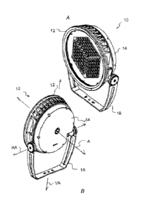
[0022] FIGs. lA and 1B are respectively front and rear perspective views of
an
embodiment of a LED lighting unit;
[0023] FIGs. 2A, 2B and 2C are respectively front, top and right side
elevational views of
the LED lighting unit of FIGs. lA and 1B;
[0024] FIG. 2D is a diagrammatic cross sectional view of FIG. 2C, while
FIG. 2E is a
diagrammatic exploded cross sectional view of FIG. 2C;
[0025] FIGs. 2F and 2G are respectively rear and left side elevational
views of the LED
lighting unit of FIGs. lA and 1B, with an embodiment of a mounting bracket
shown in
dashed lines;
- 4 -
CA 02833826 2013-11-07
WO 2012/158482 PCT/US2012/037426
[0026] FIG. 3A is an exploded front perspective view of the higher powered
LED
lighting unit of FIGs. lA and 1B;
[0027] FIG. 3B is an exploded rear perspective view of the higher powered
LED lighting
unit of FIGs. lA and 1B;
[0028] FIG. 4 is a diagrammatic front view of an embodiment of a
configurable LED
lighting unit;
[0029] FIG. 5 is a schematic diagram of an embodiment of a configurable LED
lighting
unit;
[0030] FIG. 6A is a diagrammatic side elevation view of an illumination
pattern of an
embodiment of a configurable LED lighting unit;
[0031] FIG. 6B is a diagrammatic front elevation view of the illumination
pattern
illustrated in FIG. 6A;
[0032] FIG. 7 is a diagrammatic top plan view of an embodiment of a heat
transfer
element;
[0033] FIG. 7A is a diagrammatic cross-sectional view along section line 4A-
4A of FIG.
7;
[0034] FIG. 7B is a diagrammatic right side elevational view of FIG. 7;
[0035] FIG. 7C is a diagrammatic bottom plan view of FIG. 7;
[0036] FIG. 8 is a diagrammatic cross-sectional view of an embodiment of a
chimney
accommodated within and extending through the power supply housing 14;
[0037] FIG. 9 is a diagrammatic cross-sectional view of the LED lighting
unit of the first
embodiment showing the measured average temperature readings for selected
regions of the
LED lighting unit according to the first embodiment;
[0038] FIG. 10 is a diagrammatic top plan view of a second embodiment of
the heat
transfer element;
[0039] FIG. 10A is a diagrammatic cross-sectional view along section line
7A-7A of
FIG. 10;
[0040] FIG. 10B is a diagrammatic right side elevational view of FIG. 10;
and
[0041] FIG. 11 is a diagrammatic perspective view of a third embodiment of
the heat
transfer element;
[0042] FIG. 12A and 12B are respectively cross sectional schematic views of
an
embodiment of the LED lighting unit positioned for down lighting and side
lighting
applications;
- 5 -
CA 02833826 2013-11-07
WO 2012/158482 PCT/US2012/037426
[0043] FIG. 13 is a cross sectional schematic view of an alternative
embodiment of an
LED lighting unit; and
[0044] FIG. 14 is a cross sectional schematic view of another alternative
embodiment of
an LED lighting unit.
DESCRIPTION OF THE PREFERRED EMBODIMENTS
[0045] In the following detailed description of the preferred embodiments,
reference is
made to accompanying drawings, which form a part thereof, and within which are
shown by
way of illustration, specific embodiments, by which the invention may be
practiced. It is to
be understood that other embodiments may be utilized and structural changes
may be made
without departing from the scope of the invention.
[0046] The particulars shown herein are by way of example and for purposes
of
illustrative discussion of the embodiments of the present invention only and
are presented in
the case of providing what is believed to be the most useful and readily
understood
description of the principles and conceptual aspects of the present invention.
In this regard,
no attempt is made to show structural details of the present invention in more
detail than is
necessary for the fundamental understanding of the present invention, the
description taken
with the drawings making apparent to those skilled in that how the several
forms of the
present invention may be embodied in practice. Further, like reference numbers
and
designations in the various drawings indicate like elements.
[0047] Referring first to FIGs. lA and 1B, an LED lighting unit 10,
according to the
invention, is illustrated which includes a solid state LED array assembly,
e.g., an LED array
assembly 13, positioned and oriented at a front of the lighting unit 10, and a
power supply
assembly 15, positioned at a rear of the lighting unit 10, coupled to but
located directly
behind the LED array assembly 13. The LED array assembly 13 and the power
supply
assembly 15 of the illustrative embodiment are both generally cylindrical in
shape, that is, are
of generally circular cross section with a diameter greater than their
respective heights and/or
thicknesses.
[0048] The LED assembly 13 includes a solid-state array housing including,
for example
LED lighting elements, referred to herein as an LED array housing 12. In an
illustrative
embodiments, the LED array housing 12 has a front diameter of approximately
17.25 inches
and tapers to a rear side diameter of approximately 15.6 inches over a total
housing thickness
of approximately 3.25 inches. The power supply assembly 15 includes a power
supply
- 6 -
CA 02833826 2013-11-07
WO 2012/158482 PCT/US2012/037426
housing 14, which is spaced apart from a rear surface of the LED array housing
12, for
example, by approximately 1.75 inches having a front diameter of approximately
14.9 inches
and tapering to a rear side diameter of approximately 14.25 inches over a
thickness of
approximately 2.8 inches. Both the LED array housing 12 and the power supply
housing 14
include a thermally conductive and supportive material, such as cast aluminum,
for example,
having a wall thickness of about 0.25 to 0.5 inches, provided with a polyester
powder coat
finish and sealed according to International Safety Standard IP66.
[0049] It will be appreciated and understood, however, that in at least
some
embodiments, the cross sectional shapes of the array housing 12 and the power
supply
housing 14 are generally defined by the shape of the LED array, which is
described in detail
in a following description, as are the dimensions of the LED array housing 12
and the power
supply housing 14. It will also be understood that other cross sectional and
longitudinal
shapes, such as square, rectangular or polygonal for example, are possible and
fall within the
scope of the present invention.
[0050] As shown, the lighting unit 10 is typically supported by a
conventional mounting
bracket 16 which allows for adjustment of the lighting unit as may be
beneficial in causing or
otherwise directing illumination in a preferred direction. For example, the
mounting bracket
16 can allow for vertical rotation of the lighting unit 10 about a horizontal
axis HA, which
passes through the lighting unit 10 at a location approximately centrally
between the LED
array housing 12 and the power supply housing 14 at approximately a center of
balance of the
lighting unit 10. Alternatively or in addition, the mounting bracket 16 can
allow for
horizontal rotation about a vertical axis VA. It will be understood, however,
that a lighting
unit 10 may be supported or mounted by any of a wide range of other
conventional mounting
designs and/or configuration, including both fixed mounts and positional
mounts of various
types.
[0051] A power/control cable 18 supplies power and control signals to the
LED array and
enters the lighting unit 10 though a conventional weather tight fitting 20
that is mounted in a
side wall of the power supply housing 14 (see FIG. 2F). It is to be
appreciated that the
power/control cable 18 may include separate power and control cables or a
single combined
power and control cable. In other embodiments, and in particular embodiments
having
separate power and control cables, the power cable 18 may enter power supply
housing 14
through the power cable fitting 20 while the control cable may enter through a
side or a rear
wall of the LED array housing 12 via a separate control cable fitting (not
shown).
- 7 -
CA 02833826 2013-11-07
WO 2012/158482 PCT/US2012/037426
[0052] Referring now to FIGs. 2A, 2B, 2C, 2D, 2E, 2F, 2G, 3A and 3B, the
LED array
housing 12 is shown as being generally frusto-conical in shape, and may also
be cylindrical in
shape, with a generally circular transverse cross section having a diameter
greater than the
axial length of the LED array housing 12 and a circumferential side wall 22
that gradually
slopes from its full diameter, at the front face 24 of the LED array housing
12, to a smaller
diameter forming the rear surface 26 of the LED array housing 12.
[0053] The LED array assembly 13 includes a solid state array module, e.g.,
an LED
array 28 including a symmetrically packed array of solid state lighting
elements, e.g., LEDs
30 mounted on one or more printed circuit modules 42a, 42b, 42c (generally 42)
for
generating and forming a desired light beam to be generated and transmitted by
the lighting
unit 10, when powered, with the LED array 28 being covered and protected by
one or more
optical/sealing elements 32, such as a transparent lens. The optical/sealing
element(s) 32
sealing mate with (FIG. 3A) the front face 24 of the LED array housing 12, in
a conventional
manner, providing an internal compartment, and sealing the internal
components, e.g., the
LEDs 30 and the circuit board(s) 38, from the external environment, thereby
protecting the
LED array 28 as well as the other lighting unit components contained within
the LED array
housing 12, and may include optical elements for shaping and forming the light
beam
generated and projected by the LED array 28. For example, such optical/sealing
elements 32
may include a beam shaping lens(es), an optical filter(s) of various types, an
optical mask(s),
a protective transparent cover plate(s), etc.
[0054] The power supply housing 14, in turn, contains a power supply 34
that is
connected with the power leads of the power/control cable 18 and supplies
electrical power
outputs to the LED array 28, as discussed in further detail below.
[0055] According to the present invention, each of the individual LEDs 30
of the LED
array 28 is mounted on a front surface 36 of a printed circuit board 38 (see
generally FIGs.
1A, 2A and 3A) that sized and shaped to be accommodated and mounted within the
interior
compartment 40 defined by the LED array housing 12, i.e., in close abutting
and intimate
contact with the bottom surface 26 of the LED array housing 12 to facilitate
heat transfer
thereto. The LEDs 30 include any desired and selected combination of high
powered LEDs,
such as red, green, blue or white LEDs of various color temperatures, such as
2,700K,
3,000K and/or 4,000K white light LEDs, depending upon the desired output
spectrum or
spectrums of the LED lighting unit 10.
- 8 -
CA 02833826 2013-11-07
WO 2012/158482 PCT/US2012/037426
[0056] According to one embodiment of the LED lighting unit 10, the LED
array 28
includes three separate groups, channels or arrays each including a total of
36 LEDs. The 36
LEDs of each separate group, channel or array are arranged in a 6 x 6 LED
array 42 generally
in the shape of a diamond. Each one of the three diamond shaped 6 x 6 LED
arrays 42 are
clustered together closely adjacent one another to thereby form a generally
hexagonally
shaped LED array 28, as shown in FIG. 3A, of 108 LEDs (se e FIGs. lA and 2A,
for
example). The three separate diamond shaped arrays 42 are located closely
adjacent one
another and are capable of providing approximately 9,000 lumens of total
illumination at 150
watts power consumption with an output beam having a radiating angle of
between 6 and
30 , that is, radiating angle somewhere between a narrow spotlight beam and a
floodlight
beam, depending upon the selection, type and the arrangement of LEDs 30, as
described
below, as well as the utilized optical elements 32.
[0057] It will be appreciated, however, that the LED lighting unit 10 may
be constructed
with either more or less than 108 LEDs, depending upon the particular
illumination
application, with any desired combination of LED output colors, e.g., such as
red, blue,
green, amber, cyan, royal blue, yellow, warm white and cool white, and with
greater or lesser
output power and power consumption by suitable adaptation of the embodiments
described
herein, as will be readily understood by and be apparent to those of ordinary
skill in the
relevant art.
[0058] Another embodiment of a compound solid-state lighting assembly 11 is
illustrated
in FIG. 4. The compound lighting assembly 11 includes a solid-state array
housing 12'
defining an internal compartment. In some embodiments, the compound lighting
assembly
11 has at least one transparent lens for sealing the internal compartment of
the solid-state
array housing 12'. The lighting unit 11 includes a number of solid-state
lighting circuit card
assemblies 42a', 42b', 42c' (generally 42') disposed within the solid-state
array housing 12'.
Each circuit card assembly 42' includes a common circuit card 38' and a
respective number
of solid state lighting elements 30a', 30b', 30c' (generally 30'). In the
illustrative
embodiments, a respective number of solid state lighting elements 30a' of the
first card
assembly 42a' differ in performance with respect to a respective number of
solid state
lighting elements 30b' of the second circuit card assembly 42b', both of which
differ in
performance with respect to the solid state lighting elements 30c' of the
third circuit card
assembly 42c'.
- 9 -
CA 02833826 2013-11-07
WO 2012/158482 PCT/US2012/037426
[0059] By way of illustrative example, the first circuit card assembly 42a'
is configured
with 36 LED lighting elements 30a' having a relatively narrow illumination
beamwidth (e.g.,
6 ). Likewise, the second circuit card assembly 42b' is similarly configured
with 36 LED
lighting elements 30b' having a different illumination beamwidth, such as
relatively wide
beamwidth (e.g., 30 ). The third circuit card assembly 42c' is also similarly
configured with
36 LED lighting elements 30c' having yet another different illumination
beamwidth, such as
relatively medium beamwidth (e.g., 20 ). Such different illumination
beamwidths can be
provided by the LED lighting elements themselves, optics (e.g., lenses,
shrouds) provided in
combination with the lighting elements, or some combination of the lighting
elements and
optics.
[0060] An example of illumination provided by such a configuration of
different
beamwidth LED lighting elements within the same lighting unit 11 is
illustrated in FIGs. 6A
and 6B. In particular, the different beamwidths of illumination originating
from a common
lighting unit provide a compact profile lighting source configured to provide
a wide range of
illumination. Such illumination can be advantageous in at least some
applications in which a
relatively uniform illumination is desired on a given structure, such as a
building or other
structure (e.g., bridge, sign).
[0061] In the illustrative example, an upward illumination is provided by
the lighting unit
11 to illuminate the side of a structure 41, such as a building. The
relatively wide
illumination beamwidth el (e.g., 30 ) illuminates above a relatively low
height 111. Likewise,
a relatively medium illumination beamwidth 02 (e.g., 20 ) illuminates above a
relatively
medium height H2, greater than 111; whereas, a relatively narrow illumination
beamwidth 03
(e.g., 6 ) illuminates above a relatively tall height H3, which is greater
than either 111 and H2.
A front elevation view of illumination provided by such a configuration is
illustrated in FIG.
6B.
[0062] Referring next to FIG. 5, a schematic diagram of an embodiment of
the
configurable LED lighting unit 11 is shown. The lighting unit 11 includes an
LED array
housing 12' including three lighting circuit card assemblies 42a', 42b', 42c'.
Each circuit
card assembly 42' includes a respective printed circuit board 38', which in at
least some
embodiments, can be identical, despite differences in illumination provided by
the lighting
circuit card assemblies 42'. Such common elements enhance manufacturability
and tend to
reduce production costs. In at least some embodiments, different illumination
is provided by
- 10 -
CA 02833826 2013-11-07
WO 2012/158482 PCT/US2012/037426
populating each respective printed circuit board 38' with different LED
lighting elements 30'.
Alternatively or in addition, other differing features adapted to alter
illumination, such as
optical elements (e.g., lenses, shrouds, filters, polarizers), can be combined
with the
respective circuit card assemblies 42'.
[0063] Also shown are a power supply 34' and control circuitry 44' provided
within a
separate, power supply housing 14'. In the illustrative example, an interior
cavity of the
power supply housing 14' is physically isolated from the LED array housing
12', such that
replacement, reconfiguration, or more generally, physical access to the
lighting circuit card
assemblies 42' can be accomplished without disturbing either the power supply
34' or the
control circuitry 44'. In at least some embodiments, the two separate housings
12', 14' are
interconnected by cabling 18' providing one or more of electrical power and
control signals
between the LED array housing 12' and the power supply housing 14'. Such
physical
isolation of the different elements of the lighting unit 11 can be
advantageous in controlling
access, for example, allowing maintenance personnel to access the LED array
housing 12'
without disturbing or otherwise exposing such personnel to higher voltages
that may be
present within the power supply housing 14.
[0064] Although the illustrative example includes different beamwidths, it
is understood
that other aspects affecting illumination provided by the solid-state lighting
unit 11 can be
controlled by selection and/or combination of various lighting elements 30'
with differing
features within the multiple solid-state lighting circuit card assemblies 42'.
Such features can
include one or more of illumination color and illumination color temperature.
It is also
understood that in some embodiments, substantially all of the lighting
elements 30' of a
particular lighting circuit card assembly 42' can be substantially identical;
whereas, in other
embodiments, the lighting elements 30' of a particular lighting circuit card
assembly 42' may
differ. An example of such differences may be a particular combination of
different color
and/or different color temperature LED lighting elements 30' on one lighting
circuit card
assembly 42' that differs from a combination of LED lighting elements 30' of
any of the
other lighting circuit card assemblies 42'.
[0065] As known by those of skill in the relevant art, the color or the
color temperature
output of the LED array 28 may include any desired color combination of LEDs
30 and may
be controlled by a dimmer control for the LEDs 30, forming the LED array 28,
so that the
relative illumination level output of, the individual LEDs 30 in the array,
combine to provide
the desired color or color temperature for the lighting unit output. According
to the present
- 11 -
CA 02833826 2013-11-07
WO 2012/158482 PCT/US2012/037426
invention, the dimming control of the individual LEDs 30, forming the LED
array 28, can be
provided by one or more control circuits 44, which are controlled by signals
transmitted to
each LED lighting unit 10 through the control/power cable 18 according to
industry standard
protocols, such as and for example, the industry standard DMX512 protocol, the
DALI
protocol, the digital signal interface (DSI), or the remote device management
(RDM)
protocol. Such control circuits 44 can be integrated, for example, in the one
or more circuit
boards 38 of the LED array assembly 13.
[0066] As generally illustrated in FIG. 3A, the control circuits 44 for the
LEDs 30 of the
LED array 28 are mounted on the front surface 36 of the circuit board 38 and
are generally
disposed circumferentially about the LED array 28. The control leads (not
shown), which
connect the control outputs of the control circuits 44 to the individual LEDs
30, can also be
formed on the front surface 36 of the printed circuit board 38. The power
leads (not shown),
which connect the power output of the power supply 34 in power supply housing
14 to the
control circuits 44 and the LEDs 30, are also coupled to the front surface 36
of the printed
circuit board 38 for suitable powering of the various that the LEDs 30.
[0067] According to the present invention, the rear surface 26 of the LED
array housing
12 generally includes a thermally conductive heat transfer element 50. A rear
surface 52 of
the printed circuit board 38 is generally provided in intimate contact with
the heat transfer
element 50 so as to facilitate conduction of the heat, generated by the LEDs
30, from the
circuit board 38 and into the heat transfer element 50 for subsequent
transferred to
surrounding air, as will be discussed below in further detail. During
operation of the LED
lighting unit 10, the printed circuit board 38, supporting the LED array 28,
generally absorbs,
transfers and/or otherwise carries away the heat which is generated by the
LEDs 30.
Accordingly, in such embodiments it is important that the rear surface 52 of
the printed
circuit board 38 be in thermally conductive contact with the adjacent surface
of the heat
transfer element 50.
[0068] To facilitate the desired heat transfer from the printed circuit
board 38, the heat
transfer element 50 is preferably manufactured from a thermally conductive
material, such as
aluminum or similar material or metal which readily conducts heat. When
printed circuit
board 38 is mounted within the LED array housing 12, an adjacent surface of
the heat transfer
element 50 is thus located in thermally conductive contact with the rear
surface 52 of the
printed circuit board 38 and thereby forms a continuous thermally conductive
path from the
- 12 -
CA 02833826 2013-11-07
WO 2012/158482 PCT/US2012/037426
LEDs 30 through the printed circuit board 38 into the heat transfer element 50
to facilitate
conduction thereto of heat generated from the LEDs 30.
[0069] Referring now to the assembly of the LED array housing 12 and the
power supply
housing 14, as illustrated in FIGs. 3A and 3B, the LED array housing 12 is
mounted to the
power supply housing 14 via three or more perimeter support posts 54, e.g.,
typically between
three and eight and preferably about 4 to 6 support posts 54, that extend
between and
interconnect the LED array housing 12 with the power supply housing 14. Each
support post
54 of the example embodiment has a threaded recess, in a free remote end
thereof, while the
power supply housing 14 as a mating aperture, which permits a conventional
threaded
fastener to pass through the mating aperture to threadedly engage the threaded
recess of the
support post 54, thereby fixedly connecting the two housings to one another.
Typically the
support posts 54 are spaced about the periphery of the heat transfer element
50 so as not to
hinder, as will be discussed below in further detail, the airflow through and
along the heat
transfer element 50.
[0070] It should be appreciated that support posts 54 generally
mechanically connect and
secure the LED array housing 12 to the power supply housing 14 while also
preventing the
direct conduction of heat from the LED array housing 12 to the power supply
housing 14, or
vice versa. That is, the support posts 54 of the LED lighting unit 10 are
designed to minimize
the transfer of heat from the LED array housing 12 to the power supply housing
14.
Accordingly, the support posts 54 include one or more conventional thermally
isolating
elements or components, for example, and/or may have a reduced diameter end
which
minimizes the heat transfer capacity along the support post 54 to the power
supply housing
14. Minimum lengths of the one or more support posts 54 are generally
sufficient to maintain
at least some degree of physical separation between the LED array housing 12
and the power
supply housing 14.
[0071] In at least some embodiments, a cable conduit 56 also extends
between the LED
array housing 12 and the power supply housing 14. Such a cable conduit 56
generally
includes a hollow internal passage, which facilitates the passage of
associated leads or
electrical wires between the power supply 34 and/or the control circuitry of
LED array 28.
[0072] As best shown in FIGs. 3B, 7, 7A, 7B and 7C, the rear surface 26 of
the LED
array housing 12 is provided with multiple generally parallel extending heat
dissipation
elements 60, e.g., generally twelve spaced apart elongate members or ridges,
which project
into an airflow space 62 formed between the rear surface 26 of the LED array
housing 12 and
- 13 -
CA 02833826 2013-11-07
WO 2012/158482 PCT/US2012/037426
the front surface 58 of the power supply housing 14. As shown in FIG. 7, the
two outer most
heat dissipation elements 60 are both continuous and extend generally parallel
to one another,
from one lateral side to the opposite lateral side of the LED lighting unit
10, while the inner
heat dissipation elements 60, located therebetween, are each discontinuous and
generally
extend radially inward and toward a central axis A of the LED lighting unit 10
which extends
normal to the rear surface 26 of the LED array housing 12. Such arrangement of
the inner
heat dissipation elements 60 has a tendency of channeling and/or directing air
radially
inwardly and toward the central region of the airflow space 62, i.e., toward
the central axis A,
between the rear surface 26 of the LED array housing 12 and the front surface
58 of the
power supply housing 14.
[0073] Each of the heat dissipation elements 60 of the illustrative example
generally has
the shape of a rectangular member or ridge, which extends radially inward into
and provides
access to the airflow space 62. Each generally rectangular shaped heat
dissipation element 60
is thickest at its base where it is integrally connected with the rear surface
26 of the LED
array housing 12 but becomes gradually thinner as the heat dissipation element
60 projects
away from the base, extending upwards toward the power supply housing 14. It
is to be
appreciated that the heat dissipation elements 60 generally do not contact,
but are each spaced
from, the front surface 58 of the power supply housing 14 so as to avoid
transferring or
conducting heat thereto. The exposed peripheral edges of the heat dissipation
elements 60
are generally smooth and/or rounded so as to allow the air to flow around and
by those edges
without causing undue turbulence to the air which, in turn, assists with
increasing the airflow
through the airflow space 62 and dissipation or removal of heat from heat
dissipation
elements 60 of the heat transfer element 50.
[0074] As illustrated, the heat dissipation elements 60 each generally
extend from the rear
surface 26 of the LED array housing 12 and toward the front surface 58 of the
power supply
housing 14 but are slightly spaced from the front surface 58 of the power
supply housing 14,
e.g., are spaced therefrom by a distance of about 0.25 inches or less, thereby
forming a
thermal isolation gap which thermally isolates the LED array housing 12 from
the power
supply housing 14 and significantly reduces the direct transfer of heat from
the LED array
housing 12, supporting the electrically powered LED array 28, to the power
supply housing
14 containing the power supply 34.
[0075] It should be noted that the thermal conductivity between the heat
dissipation
elements 60 and the power supply housing 14 may also be reduced while allowing
the heat
- 14 -
CA 02833826 2013-11-07
WO 2012/158482 PCT/US2012/037426
dissipation elements 60 to be in contact with the power supply housing 14 by,
for example,
minimizing the surface contact area between each heat dissipation element 60
and the power
supply housing 14 or by interposing a thermal isolation element, such as a
thermally non-
conductive spacer, between the leading edge of each heat dissipation element
60 and front
surface 58 of the power supply housing 14.
[0076] In addition to providing heat dissipation areas for transferring
heat from the LED
array housing 12 to the surrounding air, the heat dissipation elements 60, the
rear surface 26
of the LED array housing 12 and the adjacent front surface 58 of the power
supply housing
14 together form multiple convective inlet passages 66 which allow inlet of
convective
airflow into the airflow space 62, which can remove heat from by the heat
dissipation
elements 60 during operation of the LED lighting unit 10, as will be discussed
below.
[0077] The effectiveness and efficiency of this convective heat transfer
is, as is well
understood by those of skill in the relevant art, a function of the interior
dimensions, the
lengths and the number of convective circulation passages 66, as well as the
surface
characteristics of the heat dissipation elements 60, the rear surface 26 of
the LED array
housing 12 and the front surface 58 of the power supply housing 14. For
example, the
interior dimensions and the lengths and the characteristics of the interior
surfaces of the
convective inlet passages 66 as well as the shape or contour of the airflow
space 62
determines the type, the velocity and the volume of the convective airflow
that is allowed to
flow into the convective inlet passages 66. As such, these features are
significant factors in
determining the overall efficiency and the rate of heat transfer from the heat
dissipation
elements 60 to the air flowing into the convective inlet passages 66 and
contacting with and
remove heat from the exposed surfaces of the heat dissipation elements 60 of
the heat transfer
element 50.
[0078] This example embodiment generally defines a total of 22 convective
inlet
passages 66 with 11 convective inlet passages 66 being located along each
oppose lateral side
of the LED lighting unit 10. That is, each convective inlet passage 66 is
generally defined by
a pair of adjacent heat dissipation elements 60 located on either side thereof
as well as the
rear surface 26 of the LED array housing 12 and the front surface 58 of the
power supply
housing 14. Accordingly, each heat dissipation passage 66 generally has a
width of between
approximately 0.3 to 1.5 inches preferable about 0.75 inches, a height of
between
approximately 1.0 to 2.0 inches preferable about 1.5 inches, and a length
ranging between
- 15 -
CA 02833826 2013-11-07
WO 2012/158482 PCT/US2012/037426
approximately 1.0 to 4.5 inches preferable about 3.25 inches or so, depending
upon the
location of the passage 66.
[0079] The heat dissipation elements 60 thereby provide a desired heat
dissipation area
for dissipating heat generated by the LED array 28 and transferred to the rear
surface 26 of
the LED array housing 12 while the non-conductive thermal isolation gaps 64,
between the
remote free ends of the heat dissipation elements 60 and the front surface 58
of the power
supply housing 14, significantly reduce the transfer of any heat directly from
the LED array
housing 12 to the power supply housing 14 and thereby significantly reducing
adverse mutual
heating effects of the LED array 28 to the power supply 34.
[0080] In some embodiments, the rear surface 26 of the LED array housing 12
also
accommodates multiple spaced apart generally cylindrical or conical pins 68 in
addition to
the generally rectangular shaped heat dissipation elements 60. For example,
the rear surface
26 accommodates typically between 20 and 500 pins, more preferably between 100
and 300
pins, preferably about 206 pins (see FIG. 7), which extend generally normal to
the rear
surface 26 of the LED array housing 12. Each one of these cylindrical or
conical pins 68 is
generally uniformly spaced from each adjacent pin 68 and cooperates with the
heat
dissipation elements 60 to maximize a random convection airflow through the
airflow space
62 as well as heat transfer from the cylindrical or conical pins 68 to the air
so as to maximize
cooling of the LED lighting unit 10. Typically each pin 68 is generally
cylindrical in shape
and has a diameter of between approximately 0.3 to 0.65 inches preferable
about 0.35 inches
and a height of between approximately 0.6 to 1.75 inches, preferable between
about 0.9 and
1.5 inches. It is to be appreciated that the somewhat thinner pins 68 tend to
provide more
efficient transfer of the heat from the LED array housing 12 to the air than
thicker pins 68
which tend to be less efficient.
[0081] Each of the heat dissipation elements 60 has an approximate height
of between
approximately 0.6 to 1.75 inches, preferable between about 0.9 and 1.5 inches,
measured
relative to the rear surface 26 of the LED array housing 12, a width or
thickness of
approximately 0.25 to 0.45 inches, preferably about 0.4 inches, of an inch
tapering or
narrowing in a direction away from the rear surface 26, for example, with the
taper being
approximately 6 , and a length ranging from about 2 to 10 inches, depending
upon their
location across the diameter of the LED array housing 12, and may be spaced
apart by a
distance on the order of 1.0 to 1.5, preferably about 1.35 inches or so. As
generally shown in
FIG. 7A, the rear wall of the LED housing 12 may be domed or otherwise crowned
so as to
- 16 -
CA 02833826 2013-11-07
WO 2012/158482 PCT/US2012/037426
be located slightly closer to the front surface of the power source housing
14, i.e., decrease
the height of the airflow space, and this configuration facilitates
accelerating of the air as the
air flows through the airflow space 62.
[0082] With reference now to FIG. 8, a detailed discussion concerning a
chimney 70,
which is formed in and extends through the power supply housing 14. As shown,
the
chimney 70 extends from the front surface 58 of the power supply housing 14 to
the rear
surface of the power supply housing 14 and thus forms a through opening 72
through a
central region of the power supply housing 14. In the illustrative example,
the chimney 70
includes first and second conically shaped sections 74, 76 which join with one
another at a
generally narrower throat section 78. That is, each one of the first and
second conically
shaped sections 74, 76 generally has a wider diameter at either the front
surface 58 (e.g.,
having a diameter of between 1.0 inches to 2.5 inches, preferably about 2.12
inches) or the
rear surface of the power supply housing 14 (e.g., having a diameter of
between 1.0 inches to
2.5 inches, preferably about 1.94 inches) and a narrower diameter at the
throat section 78
(e.g., having a diameter of between 0.75 inches to 1.5 inches, preferably
about 1.0 to 1.2
inches). The chimney 70 is generally concentric with the central axis A of the
LED lighting
unit 10 as such positioning generally improves the airflow into and through
the LED lighting
unit 10.
[0083] In some embodiments, a central region of the heat transfer element
50 includes
three arcuate walls 80 to assist with directing airflow into the chimney.
These three arcuate
walls 80 generally are arranged in an interrupted circle and are generally
concentric with both
the longitudinal axis A and the chimney 70. Six centrally located pins 68 are
located within a
region defined by the three arcuate walls 80 and these six pins 68 are
generally separated
from the remaining pins 68 by the three arcuate walls 80. These six centrally
located pins 68
are in intimate communication with air for such air is directed into the
chimney 70.
[0084] During operation of the LED lighting unit 10, the LEDs 30 generate
heat which is
conducted to and through the printed circuit board 38 and into the rear
surface 26 of the LED
array housing 12. As the heat transfer element 50 absorbs heat, ambient air
naturally begins
to flow into and through each one of the convective inlet passages 66 and into
the airflow
space 62 located between the rear surface 26 of the LED array housing 12 and
the front
surface 58 of the power supply housing 14. As this ambient air flows in
through each one of
the convective inlet passages 66 from a peripheral space between the rear
surface 26 of the
LED array housing 12 and the front surface 58 of the power supply housing 14,
the air
- 17 -
CA 02833826 2013-11-07
WO 2012/158482 PCT/US2012/037426
generally directed radially inwardly toward the central axis A of the LED
lighting unit 10.
As the cooler ambient air flows along this radially inward path, the air
contacts with the
exterior surface of the rectangular heat dissipation elements 60 and the heat
is readily
transferred from the rectangular heat dissipation element 60 to the air. Such
heat transfer in
effect cools the rectangular heat dissipation element 60 so that such elements
may in turn
conduct additional heat away from the LEDs 30.
[0085] For embodiments including pins 68, the air continues to flow
radially inward, the
air contacts one or more of the pins 68 and, as a result of such contact,
additional heat is
transferred from the pins 68 to the air which further increases the
temperature of the air while
simultaneously cooling the pins 68. Once the heated air generally reaches the
central axis A,
the heated air communicates with the three accurate walls and the six
centrally located pins
68 before flowing into the chimney 70 and thus flowing axially along the
central axis A and
through the chimney 70 and out through the rear surface of the power supply
housing 14.
This airflow pattern, from the convective inlet passages 66 through the
airflow space 62 and
out through the chimney 70 maximizes convection airflow through the LED
lighting unit 10
and thus achieves maximum cooling of the LED lighting unit 10.
[0086] As described, heat is transferred from the exterior surface of the
rectangular heat
dissipation elements 60 to air located within the airflow space 62, between
the LED array
housing 12 and the power supply housing 14. Such heating of air within the
airflow space 62
reduces its density, also increasing its buoyancy. The heated air being more
buoyant
naturally rises. For arrangements in which the power supply housing 14 is
located above the
LED array housing 12, as would be for downward directed illumination, the
rising heated air
encounters the front surface 58 of the power supply housing 14. When
configured with a
chimney 70, at least a portion of the heated air is directed upward through
the chimney 70,
exiting the LED lighting unit 10. This creates an upward draft removing heated
air from the
airflow space 62 and creating a relative pressure drop within the airflow
space 62 compared
to ambient air. As a result of the relative pressure difference, ambient air
is drawn into the
airflow space 62, for example, through the inlet passages 66, heated and
directed through the
chimney 70 resulting in a continual natural draft-driven cooling process.
[0087] With reference now to FIG. 9, the average temperature readings for
four (4)
different locations of the LED lighting unit 10, according to the first
embodiment discussed
above, are shown. For example, the average temperature for the rear surface of
the LED
lighting unit 10 is typically about 96.0 C, the average temperature at the
outer edge of one of
- 18 -
CA 02833826 2013-11-07
WO 2012/158482
PCT/US2012/037426
the rectangular heat dissipation element 60 of the LED lighting unit 10 is
typically about
102.3 C, the average temperature for the front surface 36 of the circuit board
of the LED
lighting unit 10 is typically about 80.7 C, while the average temperature for
the outer
circumference edge of the front surface 24 of the LED array housing 12 is
typically about
98.4 C. It is to be appreciated that this arrangement generally provides
particularly efficient
cooling of the LEDs 30 as well as the internal circuitry of the LED lighting
unit 10.
Nevertheless, the following discusses a couple of alternative arrangements for
the rear
surface 26 of the LED array housing 12. Moreover, it is to be appreciated that
other
modifications and/or alterations of the rear surface 26 of the LED array
housing 12, in
accordance with the teachings of the invention discussed above, would be
readily apparent to
those of ordinary skill in the art.
[0088] Turning now to FIGs. 10, 10A and 10B, a second alternative
embodiment of a
heat transfer element 50' will now be described. As this second embodiment is
similar to the
first embodiment in many respects, only the differences between the second
embodiment and
the first embodiment will be discussed in detail.
[0089] As best shown in FIG. 10, a rear surface 26' of the LED array
housing 12' is
provided with multiple generally parallel extending heat dissipation elements
60', e.g.,
generally twelve spaced apart elongate members 60', which project into
elongated airflow
spaces 62' disposed between the rear surface 26' of the LED array housing 12'
and the front
surface 58 of the power supply housing 14. Each one of the heat dissipation
elements 60'
generally extends parallel to one another from one lateral side to the
opposite lateral side. In
the illustrative embodiment, each one of the heat dissipation elements 60' is
interrupted at
mid section, thus forming an elongate channel 82. This elongate channel 82
extends normal
to each one of the heat dissipation elements 60' and is coincident with a
diameter of the LED
lighting unit 10 which is also coincident with the central axis A of the LED
lighting unit 10.
Such arrangement of the heat dissipation elements 60' has a tendency of
directing air radially
inwardly and toward the elongate channel 82 where the air can then be directed
radially
outwardly along the elongate channel 82, i.e., in both directions along the
elongate channel
82 away from the central axis A, and thus out of the airflow space 62' defined
between the
rear surface 26' of the LED array housing 12' and the front surface 58 of the
power supply
housing 14. This arrangement is somewhat useful in the event that a chimney 70
is not
provided in the rear surface of the power supply housing 14. Alternatively, if
so desired, this
embodiment of the heat transfer element 50' can be used in combination with a
chimney 70
- 19 -
CA 02833826 2013-11-07
WO 2012/158482 PCT/US2012/037426
so that the air enters along both lateral sides of the LED lighting unit 10,
flows along the heat
dissipation elements 60' and is eventually exhausted up through the chimney 70
provided in
the power supply housing 14.
[0090] Turning now to FIG. 11, a third alternative version of the heat
transfer element 50'
will now be described. As this third embodiment is similar to the second
embodiment in
many respects, only the differences between the third embodiment and the
second
embodiment will be discussed in detail.
[0091] As shown in FIG. 11, the rear surface 26" of the LED array housing
12" is
provided with multiple generally parallel extending heat dissipation elements
60", e.g.,
generally twelve spaced apart elongate members, which project into the airflow
space 62"
formed between the rear surface 26" of the LED array housing 12" and the front
surface 58 of
the power supply housing 14. Each one of the heat dissipation elements 60"
generally
extends parallel to one another from one lateral side to the opposite lateral
side. Such
arrangement of the heat dissipation elements 60" has a tendency of directing
air from one
lateral side to the opposite lateral side where the air can then be directed
outward from the
airflow space 62" defined between the rear surface 26 of the LED array housing
12" and the
front surface 58 of the power supply housing 14. This arrangement is somewhat
useful in the
event that a chimney 70 is not provided in the rear surface of the power
supply housing 14.
Alternatively, if so desired, this embodiment of the heat transfer element 50"
can be used in
combination with a chimney 70 so that the air enters from both lateral sides
of the LED
lighting unit 10, flows along the heat dissipation elements 60" and is
eventually exhausted up
through the chimney 70 provided in the power supply housing 14.
[0092] FIG. 12A and 12B are respectively cross sectional schematic views of
an
embodiment of the LED lighting unit 100 positionable between downward (FIG.
12A)
lighting and lateral (FIG. 12B) lighting applications. Such positioning can be
accomplished,
for example, with the standard mounting bracket can allow for vertical
rotation of the lighting
unit 100 about a horizontal axis HA (e.g., FIG. 1B). The LED lighting unit 100
includes an
LED array housing 112 projecting illumination 102 in a preferred direction as
shown. A heat
transfer element 150 is mounted to a rear surface of the LED array housing
112, configured
to draw heat away from internal lighting elements. The LED lighting unit 100
also includes a
separate power supply housing 114 positioned in an overlapping, spaced-apart
arrangement
with the LED array housing 112. An airflow space 162 is defined between
overlap of the two
separate housings 112, 114. The power supply housing 114 includes a centrally
located
- 20 -
CA 02833826 2014-06-26
lumen, or chimney 70 extending through the power supply housing 114.
[00931 When positioned for downward illumination as shown in FIG. 12A, the
heat
transfer element 150 heats air within the airflow space 162, creating an
upward draft through
the chimney 170, as shown at 171. The upward draft draws cooler ambient air
173 laterally into the
airflow space 162, which results in a continual cooling of the LED lighting
unit 100.
[00941 When positioned for lateral illumination as shown in FIG. 128, the
heat transfer
element heats air within the airflow space 162, creating an upward draft.
Instead of being
directed through the chimney 170, however, the heated air exits the airflow
space 162 from a
top portion of the void between the LED array housing and the power supply
housing 114. In
at least some embodiments, the heat transfer element 150 includes vertical
passageways, such
as flutes or openings between ridges and/or pins that are largely unobstructed
to promote a
draft according to the direction indicated by the arrows 175. When positioned
between downward
and lateral lighting, cooling can be enhanced by a combination of a portion of
air heated
within the airflow space 162 exiting through the chimney 170 and a portion
exiting at an
upper lateral region or edge of the airflow space 162. As the warm air
naturally rises, the
heated air will rise creating a draft drawing in cooler, ambient air 177 at
least through a lower
lateral region or edge of the airflow space 162.
[00951 FIG. 13 is a cross sectional schematic view of an alternative
embodiment of an
LED lighting unit 200 for upward illumination. The LED lighting unit 200
includes an LED
array housing 212 projecting illumination 202 in a preferred direction as
shown. A heat
transfer element 250 is mounted to a rear surface of the LED array housing
212, configured
to draw heat away from internal lighting elements. The LED lighting unit 200
also includes a
separate power supply housing 214 positioned in an overlapping, spaced-apart
arrangement
with the LED array housing 212. An airflow space 262 is defined between
overlap of the two
separate housings 212, 214. The LED array housing 212 includes a centrally
located lumen,
or chimney 272 extending through the LED array housing 212. The chimney 272
can take on
any of various shapes, such as cylindrical, frusto-conical, and the other
various chimney
configurations described herein in relation to the power supply housing 14.
[0096] When positioned for upward illumination as shown, the heat transfer
element 250
heats air within the airflow space 262, creating an upward draft through the
chimney 272, as
shown. The upward draft draws cooler ambient air 179 laterally into the
airflow space 262, which
results in a continual cooling of the LED lighting unit 200.
-21 -
CA 02833826 2015-02-23
[0097] FIG. 14 is a cross sectional schematic view of another alternative
embodiment of
an LED lighting unit 300 including two chimneys 370, 372. A heat transfer
element 350 heats
air within an airflow space 362 located between a rear surface of the LED
array housing 314 and
a front surface of the power supply housing 314. A first chimney 370 is
provided through the
power supply housing 314 as described in relation to FIG. 12A. A second
chimney 372 is
provided through the LED array housing 312 as described in relation to FIG.
13. When
combined with a standard mounting bracket that allows for vertical rotation of
the lighting unit
300 about a horizontal axis HA (e.g., FIG. I B), the LED lighting unit 300 can
provide unassisted
cooling in either upward, downward or lateral illumination positions.
[0098] Since certain changes may be made in the above described high power
light
emitting diode (LED) lighting unit for indoor and outdoor lighting functions,
without departing
from the spirit and scope of the invention herein involved, it is intended
that all of the subject
matter of the above description or shown in the accompanying drawings shall be
interpreted
merely as examples illustrating the inventive concept herein and shall not be
construed as
limiting the invention.
[0099] Many alterations and modifications of the present invention will no
doubt become
apparent to a person of ordinary skill in the art after having read the
foregoing description, it is to
be understood that the particular embodiments shown and described by way of
illustration are in
no way intended to be considered limiting. It is noted that the foregoing
examples have been
provided merely for the purpose of explanation and are in no way to be
construed as limiting of
the present invention.
[00100] While the present invention has been described with reference to
exemplary
embodiments, it is understood that the words, which have been used herein, are
words of
description and illustration, rather than words of limitation.
[00101] Although the present invention has been described herein with
reference to
particular means, materials and embodiments, the present invention is not
intended to be limited
to the particulars disclosed herein.
- 22 -