Note: Descriptions are shown in the official language in which they were submitted.
CA 02833829 2013-10-21
WO 2012/172174
PCT/F12012/050595
1
EQUIPMENT TO PREPARE ORE CONCENTRATE FOR PELLETIZING
The invention relates to an equipment to prepare ore
concentrate for pelletizing and sintering/indurating
of pellets in connection with ferroalloys production.
A prior art process and equipment for the production
of ferroalloys is schematically shown in Figure 1. For
example, the shown prior art process may relate to the
production of ferrochrome from chromite concentrates
but it can also be applied to the production of other
ferroalloys.
The raw material is obtained from a mine. The ore
concentrate is stored and initially fed to the process
from a day bin 7. Typically the ore concentrate has
moisture content more than 1%. The equipment further
comprises a grinder 1 for grinding the coarse ore con-
centrate to a predetermined grain size which is suita-
ble for the subsequent pelletizing step.
In prior art the grinder 1 is a wet grinder, such as a
ball mill, whereto the material to be ground is fed
together with the addition of water. A ball mill 1 is
a rotating drum which is partially filled with the ma-
terial to be ground and grinding medium. Different ma-
terials are used as grinding media, including ceramic
balls, flint pebbles and steel balls. As the drum ro-
tates the grinding media rise with the aid of centrif-
ugal force along with the inner surface of the drum
and eventually fall on the material to be ground. Var-
ious factors, like the size of the grinding media and
CA 02833829 2013-10-21
WO 2012/172174 PCT/F12012/050595
2
the rotation speed of the drum, affect to the degree
of grinding.
The wet grinder 1 is followed by a slurry mixer 8
which is arranged to mix the slurry discharged from
the wet grinder 1.
The slurry mixed in the slurry mixer is then led to
filter 9, which can be a capillary-effect ceramic disc
filter. The filter 9 is arranged to dewater the con-
centrate slurry by filtering to form a dewatered min-
eral concentrate.
From the filter 9 the concentrate is conveyed to in-
termediate bins 10. Also other additives, solid fuel
(coke fine which acts as a fuel in the subsequent sin-
tering/indurating process), process dust and binding
agent (bentonite clay) are conveyed to first interme-
diate bins 10.
The concentrate and the additives are distributed from
the intermediate bins 10 onto a conveyor 11 which con-
veys these materials to a mixer 12.
The mixer 12 is arranged to mix the concentrate with
solid fuel, process dust and binder to form a homoge-
nous mixture of these. Also an amount of water can be
added into the mixer 12 to ensure that the mixture has
sufficient moisture content for pelletizing.
CA 02833829 2013-10-21
WO 2012/172174
PCT/F12012/050595
3
Further, the equipment comprises a pelletizing drum or
disc 13 which is arranged to pelletize the mixture ob-
tained from the mixer 12 to green pellets.
Further, the process equipment includes a roller
screen 14 to ensure that uniformly sized green pellets
only are fed as an even pellet bed to the endless con-
veyor belt of the strand sintering/indurating furnace
15.
In the continuously working strand sinter-
ing/indurating furnace 15 the pellet bed is exposed to
subsequent drying, heating, sintering/firing and cool-
ing steps, each of them having different temperature
conditions, as the pellet bed is conveyed through re-
spective zones of the furnace 15. The sinter-
ing/indurating furnace includes circulation gas ducts
16, 17, 18 which circulate gas from the cooling zones
to the drying, heating and sintering/firing zones for
the purpose of saving energy. After the sinter-
ing/indurating the pellets are spherical, uniformly
sized, hard and porous with consistent physical and
chemical properties. They are ideal charging material
for ferroalloy smelting in the smelting furnace 5.
From the strand sintering/indurating furnace 15 the
pellets are conveyed to second intermediate bins 19.
Reference number 19 also refers to bins for additives,
like lumpy ore, coke, and quartz sand which together
with pellets are charged to a preheating kiln 20.
CA 02833829 2013-10-21
WO 2012/172174 PCT/F12012/050595
4
The preheating kiln 20 is arranged to preheat the pel-
lets before charging to the smelting furnace 5. The
smelting furnace 5 is an electric arc furnace. In the
smelting furnace 5 the pellets are smelted and reduced
to ferroalloy. The molten ferroalloy discharged from
the smelting furnace 5 is casted to ferroalloy prod-
ucts suitable for further production of metal.
The carbon monoxide rich off-gas exiting from the
smelting furnace 5 is cleaned in a gas scrubber 21.
The cleaned CO gas is used as a fuel which is burned
by a burner 22 in the preheating kiln 20 to produce
the sufficient heating energy for preheating of the
pellets. The cleaned CO gas is also led to burners 23
and 24 located in the walls of the gas circulating
ducts 16 and 17 of the strand sintering/indurating
furnace 15 to heat the gas flowing in the ducts.
The problem of the prior art equipment and process re-
lates to an ever decreasing availability of good qual-
ity raw materials. More often the raw material to be
processed has a very poor quality because it contains
or forms very fine fractions, e.g. clay-like chromite.
"Fine fractions" stands typically for that 80% of par-
ticles have a size less than 75 pm. Wet filtering of
the fine fractions in order to dewater those is diffi-
cult since fine fractions tend to clog the filters.
Also the time required to dewater the material with a
ceramic filter is too long for the process and re-
quires a series of filters whereby the required in-
vestment becomes vast.
CA 02833829 2013-10-21
WO 2012/172174 PCT/F12012/050595
It is an object of the invention to overcome the dis-
advantages of the prior art as outlined above.
According to the invention the equipment comprises a
5 drying apparatus arranged to dry the concentrate be-
fore and/or during grinding by the grinder.
The invention provides many advantages. By the ar-
rangement of a drying apparatus to dry the concentrate
before and/or during grinding by the grinder it is
achieved that the concentrate can be dry ground and no
subsequent dewatering by filters is needed. With the
aid of the invention it is possible to cost-
effectively utilize raw materials containing fine
fractions which normally would be difficult to dewater
by filtering.
In one embodiment, the drying apparatus is arranged to
dry ore concentrate by the heat energy obtained from
burning carbon monoxide.
In one embodiment, the drying apparatus is arranged to
dry ore concentrate by the heat energy obtained from
burning carbon monoxide rich off-gas from a smelting
furnace. By utilizing the CO gas from the smelting
furnace to produce the sufficient heat energy for dry-
ing is advantageous because fossil fuels are thus not
needed.
In one embodiment, the drying apparatus comprises a
burning chamber comprising a burner arranged to burn
carbon monoxide and/or carbon monoxide rich off-gas to
CA 02833829 2013-10-21
WO 2012/172174 PCT/F12012/050595
6
produce hot gases, and a drying chamber arranged to
dry ore concentrate with said hot gases.
In one embodiment, the grinder comprises a grinding
chamber arranged to grind the ore concentrate during
conveyance the ore concentrate through the grinding
chamber. The grinding chamber and the drying chamber
are built together, so that hot gases from a separate
burning chamber are led to the grinding chamber.
In one embodiment, the burning chamber, the drying
chamber and the grinding chamber are built together so
that the burner producing hot gases is attached di-
rectly to the grinder.
The accompanying drawings, which are included to pro-
vide a better understanding of the invention consti-
tute part of the description, illustrate preferred em-
bodiments of the invention and help to explain the
principles of the invention.
Figure 1 shows a schematic flow chart of a prior art
ferroalloys process and process equipment,
Figure 2 shows a schematic flow chart of a ferroalloys
process and process equipment of a first embodiment of
the invention,
Figure 3 shows the beginning of the ferroalloys pro-
cess and process equipment of a second embodiment of
the invention, and
CA 02833829 2013-10-21
WO 2012/172174
PCT/F12012/050595
7
Figure 4 shows the beginning of the ferroalloys pro-
cess and process equipment of a third embodiment of
the invention.
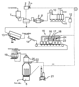
Referring to Figure 2, the raw material is obtained
from a mine. The raw
material, ore concentrate, is
stored and initially fed to the process from a day bin
7. Typically the ore concentrate has moisture content
more than 1%.
Equipment of the Figure 2 comprises a grinder 1 for
grinding the coarse ore concentrate to a predetermined
grain size which is suitable for the subsequent
pelletizing step. In contrast to the prior art equip-
ment the grinder 1 in the invention is dry grinder 1.
In order to dry the ore concentrate before it is fed
to the grinder 1 it must be dried. For that purpose
the equipment comprises a drying apparatus into which
the ore concentrate is fed from the day bin 7.
The drying apparatus comprises a burning chamber 2
comprising a burner 3. The burner 3 is arranged to
burn carbon monoxide and/or cleaned carbon monoxide
rich off-gas obtained from the smelting furnace 5 with
air to produce hot gases. The temperature of the
cleaned CO gas is about 30 C to 60 C. The
resulting
gas after burning comprises water, nitrogen, carbon
monoxide and some oxygen. The temperature of these hot
drying gases is about 300 C to 500 C.
The hot gases are led to a drying chamber 4 which is
arranged to dry ore concentrate with said hot gases.
CA 02833829 2013-10-21
WO 2012/172174 PCT/F12012/050595
8
In Figure 2 the burning chamber 2 and the drying cham-
ber 4 are separate units. The drying chamber 4 may be
a rotating drum which while it rotates conveys the ma-
terial to be dried from the charge end to the dis-
charge end.
The dried ore concentrate is fed to the dry grinder 1.
The grinder 1 comprises a grinding chamber 6 arranged
to grind the ore concentrate during conveyance the ore
concentrate through the grinding chamber. The dry
grinder 1 may be a ball mill. A ball mill 1 is a ro-
tating drum which is partially filled with the materi-
al to be ground and grinding medium. Different materi-
als are used as grinding media, including ceramic
balls, flint pebbles and steel balls. As the drum ro-
tates the grinding media rise with the aid of centrif-
ugal force along with the inner surface of the drum
and eventually fall on the material to be ground. Var-
ious factors, like the size of the grinding media and
the rotation speed of the drum, affect to the degree
of grinding. The temperature of the ore concentrate
discharged from the dry grinder 1 is less than 100 C.
After the dry grinder 1 at point A inside a circle the
process may continue in a manner as depicted in Figure
1. From the dry grinder 1 the concentrate is conveyed
to intermediate bins 10. Since the concentrate is dry,
it does not have to be dewatered by any filters like
in the prior art process of Figure 1.
Also other additives, solid fuel (coke fine which acts
as a fuel in the subsequent sintering/indurating pro-
CA 02833829 2013-10-21
WO 2012/172174 PCT/F12012/050595
9
cess), process dust and binding agent (bentonite clay)
are conveyed to the intermediate bins 10.
The concentrate and the additives are distributed from
the intermediate bins 10 onto a conveyor 11 which con-
veys these materials to a mixer 12.
The mixer 12 is arranged to mix the concentrate with
solid fuel, process dust and binder to form a homoge-
nous mixture of these. Also an amount of water can be
added into the mixer 12 to ensure that the mixture has
sufficient moisture content for pelletizing.
Further, the equipment comprises a pelletizing drum 13
which is arranged to pelletize the mixture obtained
from the mixer 12 to green pellets. Green pellets have
a sufficient cohesiveness so that they can be conveyed
and screened without breakage.
Further, the process equipment includes a roller
screen 14 to ensure that uniformly sized green pellets
only are fed as an even pellet bed to the endless con-
veyor belt of the strand sintering/indurating furnace
15.
In the continuously working strand sinter-
ing/indurating furnace 15 the pellet bed is exposed to
subsequent drying, heating, sintering/firing and cool-
ing steps, each of them having different temperature
conditions, as the pellet bed is conveyed through re-
spective zones of the furnace 15. The sinter-
ing/indurating furnace includes circulation gas ducts
CA 02833829 2013-10-21
WO 2012/172174 PCT/F12012/050595
16, 17, 18 which circulate gas from the cooling zones
to the drying, heating and sintering/firing zones for
the purpose of saving energy. After the sinter-
ing/indurating the pellets are spherical, uniformly
5 sized, hard and porous with consistent physical and
chemical properties. They are ideal charging material
for ferroalloy smelting in the smelting furnace 5.
From the strand sintering/indurating furnace 15 the
10 pellets are conveyed to a second intermediate bin 19.
Reference number 19 also refers to bins for additives,
like lumpy ore, coke, and quartz sand. The sin-
tered/indurated pellets and additives are charged to a
preheating kiln 20.
The preheating kiln 20 is arranged to preheat the pel-
lets before charging to the smelting furnace 5. The
smelting furnace 5 is a closed-type electric arc fur-
nace. In the smelting furnace 5 the pellets are smelt-
ed and reduced to ferroalloy. The molten ferroalloy
discharged from the smelting furnace 5 is casted to
ferroalloy products suitable for further production of
metal.
The carbon monoxide rich off-gas exiting from the
smelting furnace 5 is cleaned in a gas scrubber 21.
The gas scrubber 21 may be an ejector venturi scrubber
operating by wet cleaning principle.
The cleaned CO gas is used as a fuel which is burned
by a burner 22 in the preheating kiln 20 to produce
the sufficient heating energy for preheating of the
CA 02833829 2013-10-21
WO 2012/172174
PCT/F12012/050595
11
pellets. The cleaned CO gas is also led to burners 23
and 24 located in the walls of the gas circulating
ducts 16 and 17 of the strand sintering/indurating
furnace 15 to heat the gas flowing in the ducts. The
CO gas pipeline is indicated in Figure 2 with the ref-
erence marking B inside a circle.
In Figure 3 there is shown a modification of the
equipment of Figure 2. In this embodiment the grinding
chamber 6 and the drying chamber 4 are built together.
The hot gases from a separate burning chamber 2 are
led to the grinding chamber 6 which also acts as a
drying chamber 4. The burning chamber 2 is separate
from the combined grinding and drying chamber 4, 6.
Otherwise, the equipment and process may be similar to
the one depicted in Figure 2. The process may hereaf-
ter continue as indicated by the marking A inside a
circle in Figure 2. The CO gas pipeline as indicated
with the reference marking B inside a circle may be
similar to that shown in Figure 2.
In Figure 4 there is shown a further modification of
the equipment of Figure 2. In this embodiment the
burning chamber 2, the drying chamber 4 and the grind-
ing chamber 6 are all built together. The burner 3 is
attached directly to the grinder 1. The process may
hereafter continue as indicated by the marking A in-
side a circle in Figure 2. The CO gas pipeline as in-
dicated with the reference marking B inside a circle
may be similar to that shown in Figure 2.
CA 02833829 2013-10-21
WO 2012/172174 PCT/F12012/050595
12
It is obvious to a person skilled in the art that with
the advancement of technology, the basic idea of the
invention may be implemented in various ways. The in-
vention and its embodiments are thus not limited to
the examples described above; instead they may vary
within the scope of the claims.