Note: Descriptions are shown in the official language in which they were submitted.
CA 02834094 2013-11-25
SELF-CONTAINED, PORTABLE AND SELF-SUPPORTING
SCAFFOLDING KIT
FIELD OF THE INVENTION
[0001] The present invention relates to scaffoldings, and more specifically to
a
self-contained portable and self-supporting scaffolding kit, with easy-to-use
and
high safety features.
BACKGROUND OF THE INVENTION
[0002] Scaffoldings with raisable platform mounted on a tower or the like are
well known in the art of building construction. These scaffoldings require the
tower to be temporarily secured to the adjacent structure at a relatively low
height, starting at about 20 feet from ground, when carrying substantial
loads.
These attachments require the help of skilled technicians and prevent the
scaffolding from being rapidly displaced from one place to another whenever
required. Furthermore these types of scaffoldings usually include massive and
heavy sections of towers in order to carry significant loads with a relatively
small
size cross section.
[0003] There is no existing 'portable' size scaffoldings in which the overall
structure is relatively light weight for self-support while being easily
assembled
and/or disassembled by a single worker, and still allowing for the worker
being
on the vertically displaceable platform to be capable of displacing
himself/herself all along the platform through the tower.
[0004] Furthermore, existing scaffoldings always require significant amount of
equipment that usually need to be carried independently from the scaffolding
itself, such that either many back and forth displacements between two points
are required or many motor vehicles are used to carry them all. Alternatively,
a
single truck with a large loading platform could be used, but such a truck
would
have limited access to construction areas and typically requires a skilled and
licensed driver.
CA 02834094 2013-11-25
2
[0005] Similarly, existing non-raisable scaffoldings, in order to cover a
surface
of approximately 40 feet wide by 32 feet high (about 12x10 meters), requires
about 4 hours to be fully installed by a minimum of two skilled workers,
before
use.
[0006] Accordingly, there is a need for an improved self-contained portable
self-
supporting scaffolding kit.
SUMMARY OF THE INVENTION
[0007] It is therefore a general object of the present invention to provide an
improved self-contained portable self-supporting scaffolding kit.
[0006] An advantage of the present invention is that the scaffolding kit is
relatively simple and inexpensive to manufacture.
[0009] Another advantage of the present invention is that the self-supporting
scaffolding of the kit does not require to be anchored to an adjacent building
structure, up to a total height of the scaffolding equivalent to about a
maximum
of a 4-story high building.
[0010] A further advantage of the present invention Is that the self-
supporting
scaffolding kit is portable such that, when into an unassembled configuration
it
could be part of a trailer or the like for motor vehicle.
[0011] Still another advantage of the present invention is that the self-
supporting scaffolding kit is easily assembled /disassembled and installed by
a
single worker, being alone with no help.
[0012] Yet another advantage of the present invention is that the self-
supporting
scaffolding kit is fully safe for any worker and does not require any special
skill
for the operation, including assembly and disassembly, of the scaffolding.
[0013] Still another advantage of the present invention is that the self-
supporting scaffolding kit may include different working equipment, such as a
crane assembly located on top of the tower assembly, adjustable platforms
CA 02834094 2013-11-25
3
and/or extensions thereof, all this working equipment being carryable on the
same trailer as of the scaffolding, to provide for a self-contained portable
kit.
[0014] Another advantage of the present invention is that the self-supporting
scaffolding kit does not require the use of any ladder or the like to get on
and off
from the platform temporarily locked at any specific height since the tower
itself
includes the ladder to allow a user to climb along and Inside the supporting
tower.
[0015] A further advantage of the present invention is that the self-
supporting
scaffolding kit can be easily customized to provide pre-determined features to
specific users, wherever desired.
[0016] According to an aspect of the present invention there is provided a
self-
contained portable self-supporting scaffolding kit for mounting adjacent an
elevated structure and allowing a user to reach the elevated structure to work
thereon, said kit comprising:
[0017] - a support base assembly;
[0018] - a tower assembly releasably mounting on the support base
assembly, the tower assembly including a plurality of tower
sections releasably attaching to and on top of one another in an
end-to-end configuration, a lowermost said tower section
releasably attaching to the support base, each said tower section
having two opposite lateral sides with facing openings for allowing
a user to move through said tower section via said facing
openings; and
[0019] - a platform assembly being movably mounted on the tower
assembly for displacement therealong, the platform assembly
including a sleeve member mounting around the tower assembly,
and a platform member connecting to the sleeve member, the
platform member being movable between a portable configuration
with the platform member being adjacent and substantially parallel
to the sleeve member and the tower assembly, and a use
CA 02834094 2013-11-25
4
configuration with the platform member extending substantially
perpendicular to the sleeve member and the tower assembly.
[0020] Conveniently, each tower section has a rectangular, and preferably
square cross-section.
[0021] Conveniently, for each tower section, the two opposite lateral sides
are
connected to one another via a font side and a rear side, at least one of the
front and rear sides includes a ladder member.
[00221 Typically, the platform member extends on opposite sides of the sleeve
member and generally perpendicularly to the lateral sides of the tower
sections
[0023] In one embodiment, the platform member hingeably connects to the
sleeve member.
[0024] Conveniently, the platform member includes two half portions hingeably
connecting to one another.
[0025] Conveniently, the platform assembly includes a plurality of holes
slidably
receiving a respective plank support beam, the plank support beam laterally
protruding from the platform member for supporting a side platform extension
thereon.
[0026] Other objects and advantages of the present invention will become
apparent from a careful reading of the detailed description provided herein,
with
appropriate reference to the accompanying drawings.
BRIEF DESCRIPTION OF THE DRAWINGS
[0027] Further aspects and advantages of the present invention will become
better understood with reference to the description in association with the
following Figures, in which similar references used in different Figures
denote
similar components, wherein:
CA 02834094 2013-11-25
[0028] Figure 1 is a simplified schematic perspective view of a self-
contained,
protable and self-supporting scaffolding kit in accordance with an embodiment
of the present invention In the use configuration;
[0029] Figure la is an enlarged partially sectioned perspective view taken
5 along line la of Figure 1;
[0030] Figure 2 is a simplified schematic rear elevation view of the
embodiment
of Figure 1 in the use configuration;
[0031] Figure 3a is a simplified schematic rear elevation view of the
embodiment of Figure 1, shown with most equipment pieces;
[0032] Figure 3b is a view Similar to Figure 3a, showing the embodiment in the
portable configuration; and
[0033] Figure 4 is a simplified schematic side elevation view of the
embodiment
of Figure 1, in the use configuration.
DETAILED DESCRIPTION OF THE INVENTION
[0034] With reference to the annexed drawings the preferred embodiment of the
present invention will be herein described for indicative purpose and by no
means as of limitation.
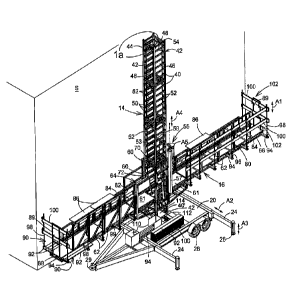
[0035] Referring to Figures 1 through 4, there is shown a self-contained and
portable self-supporting scaffolding kit 10 in accordance with an embodiment
of
the present invention. The term portable means a scaffolding kit that can
easily
be carried on a trailer by a motorized vehicle and easily assembled
/disassembled by a single worker, and that is not required to be secured to an
adjacent building structure S or the like when being used as its overall
maximum height is in the order of a four (4) story high building.
[0036] The self-contained and portable self-supporting scaffolding kit 8,
shown
in the use configuration in Figures 1, 2, and 4, Includes self-supporting
scaffolding 10 that comprises a support base assembly 12, a tower assembly 14
CA 02834094 2013-11-25
6
mounting on and attaching to the support assembly 12 and a platform assembly
16 movably (slidably) mounting on the tower assembly 14, as illustrated by
arrow Al. The support assembly 12 is typically formed of a base member 20,
preferably heavy (in the order of about 3000-4000 lbs, about 1500-2000 kg, for
example), generally in the form of closed structure of steel beams filled with
concrete or the like having a tower attachment structure 22 protruding
upwardly
therefrom, and a plurality of laterally extendable (preferably lengthwise, as
illustrated by arrow A2) mounting legs or outriggers 24 and high adjustable
(as
illustrated by arrow A3) feet 26 for stability of the scaffolding 10. The base
assembly 12 is typically mounted on wheels 28 for displacement thereof, along
with a hitch assembly 29 or the like. Accordingly, the height adjustment of
the
feet 26 allow to raise the scaffolding 10 such that it is properly
horizontally
levelled arid supported by the four legs 24 only, and not the wheels 28, when
being used.
[0037] The tower assembly 14 typically includes a plurality of tower sections
40
releasably attaching to and on top of one another in an end-to-end
configuration. A lowermost tower section 40' releasably attaches to the
attachment structure 22 of the support base assembly 12. Each tower section
40 has two opposite lateral sides 42, a front side 44 typically for facing a
building structure S or the like, and an opposite rear side 46. Each tower
section 40, 40' typically has a rectangular, and preferably square cross
section
(typically about 3,5 feet or 1 meter of side width). Each lateral side 42 has
an
opening 48 adapted to face the corresponding opening 48 of the opposite
lateral
side 42 to allow a user of the scaffolding kit 8 to move through the tower
section
26 40 via the facing openings 48.
[0036] In order to allow the users/workers to access the platform assembly 16,
at least the front side 44 of the each tower section 40 typically includes a
series
of ladder extensions or steps 50 inwardly protruding from generally horizontal
cross bars 52 thererof, as better shown in Figure la. Each tower section 40
includes an alignment feature 54 at its upper end to enable the proper
alignment
of the adjacent upper tower section 40 during assembly, and is releasably
CA 02834094 2013-11-25
7
secured to the adjacent upper tower section 40 using conventional bolts (not
shown) or the like.
[0039] The platform assembly 16 typically includes a sleeve member 80
mounting around the tower assembly 14 and a platform member 62 movably
securing to a platform base 61 of the sleeve member 60, at a lower end thereof
and laterally extending therefrom, preferably on both sides, for structural
equilibrium reasons, as shown in Figures 3a and 3b. The sleeve member 60
typically includes a crane 55 carrying a wire cable 53 usually ending with a
hook
56. In order to have the required flexibility to lift a tower section 40 for
securing
it on top of the previous tower section 40, the crane 55 typically includes a
telescopic vertical boom 57 (as illustrated by arrow A4) rotatably supporting
a
horizontal boom 58 (as illustrated by arrow A5) on which the motor/reel
assembly 59 of the wire cable 53 is slidably mounted (as illustrated by arrow
A6). The crane 55, in addition to be used for the assembly and disassembly of
the self-supporting scaffolding 10, is also used for the folding and unfolding
of
the hinged platform members 62 (as shown in Figures 3a and 3b), and for the
raising of equipment, material or the like (not shown) onto the platform
assembly 16. The platform member 62 typically extends on opposite sides of
the sleeve member 60 and generally perpendicularly to the lateral sides 42 of
the tower sections 40.
[0040] As shown in Figures 1 to 4, the sleeve member 60 is secured to the
tower assembly 14 via a lifting mechanism 64 generally located on a rear side
thereof for axial displacement relative thereto. The lifting mechanism 64
includes an electrically or hydraulically powered hook member 66 interfacing
with the series of horizontal cross bars 52 of the rear side 46 of the tower
sections 40. The sleeve member 60 slides along the tower assembly 14 using
sliding guide tabs (not shown) abutting against the four (4) corners of tower
assembly 14, typically at both the upper and lower ends of the sleeve member
60. The sleeve member 60 also includes a safety stop mechanism (not shown)
known in the art to prevent inadvertent free falling of the sleeve member 60
along the tower assembly 14. The safety stop mechanism, typically biased to
engage one of the cross bars 52, is typically selectively disengageable from
the
CA 02834094 2013-11-25
8
tower assembly 14 when the hook member 66 is engaged with one of the cross
bars 52, for allowing the displacement of the sleeve member 60 along the tower
assembly 14. Furthermore, two apertures 70 are defined on lateral sides of the
sleeve member 60 to clear off the space between the upper and lower ends
thereof. The apertures 70, when in register with the facing openings 48 of a
corresponding tower section 40, allow for a worker to step therethrough, in a
generally standing position, from one lateral side of the tower assembly 14 to
the other, on the platform member 62. For safety purposes, each aperture 70
typically includes a pair of spring doors 72 or the like, for automatic
closing
thereof, preferably openable towards the respective platform member 62.
[0041] In the embodiment shown throughout the Figures, the platform member
62 are located on each side of the sleeve member 60 and are typically
hingeably mounted onto the platform base 61. Each side of the platform
member 62 is further divided, lengthwise, Into two half portions that are
hingeably connected to one another such that, when in the portable
configuration shown in Figure 3b, both half portions are with their bottom
sides
facing one another. The handrails 80 of the platform members 62 include a
foldable upper portion 82 hingeably mounted onto a corresponding fixed lower
portion 84. The upper portions 82 are foldable to allow for a more compact
portable configuration of the scaffolding 10, and to allow the installation of
a
working table 86 whenever required, to carry construction material as bricks
and
the like at a suitable height for the workers, as best seen in Figure 1,
Platform
end members 88 at the extremities, with their respective hand rail 89, allow
for
the users/workers to freely move between the platform member 62 and
temporary and customizable front and/or rear side platform extensions 90. The
platform extensions 90 are typically provided with wooden planks 92 or the
like
supported by plank support beams 94 slidably inserted into corresponding holes
96 provided underneath the platform members 62, The width of each platform
extension 90 may vary from nothing to about six (6) feet (2 meters), about six
to
ten wooden planks 92 side by side, such that the overall width of the
scaffolding
10 could be as wide as about sixteen (16) feet (5.5 meters). The free end of
each plank support beam 94 typically releasably receives a hand rail post 98,
itself adapted to slidably receive, into slots 99, side rail planks 100 that
form the
CA 02834094 2013-11-25
9
protective hand rail 102, which is not required when the corresponding
platform
extension 90 does face the building structure S or the like,
[0042] When in the self-contained portable configuration, as shown in
Figure 3b, the slidable plank support beams 94 are typically stacked on the
base member 20 between stoppers 110, while the wooden planks 92, 100 are
typically stacked on the base member 20 beside the plank support beams 94.
The two platform end members 88 are typically located on the base member 20
beneath the respective retracted platform member 82 secured in the portable
configuration. All other small equipment are typically located into a recess
112,
provided with closing panels 114 or the like (see Figure 1), centrally located
on
the base member 20 under the tower assembly 14. The adjustable feet 26 are
raised and the mounting legs 24 are retracted into their portable
configuration.
Two (2) of the three (3) tower sections 40 are located on the rear side of the
base member 20 while the other one is located on the wooden planks 92, 100
beside the sleeve member and the lowermost tower section 40' secured to the
base member 20. All equipment is properly secured to the base assembly 12,
using straps or the like (not shown) well-known in the art, to allow for its
safe
transportation.
[0043] When fully assembled in the use configuration, as shown in Figures 1,
2,
and 4, with three tower sections 40 mounted on top on the lowermost section
40', the self-supporting scaffolding 10 essentially covers a working wall
surface
of an adjacent building structure S of about 40 feet (12 meters) long by 32
feet
(10 meters) high.
[0044] Although not illustrated, the self-supporting scaffolding kit 8 could
eventually be used with about ten (10) additional tower sections 40 (other
than
the four (4) sections shown in the drawings), to reach higher adjacent
structures, such as up to about 10 or 12-story high buildings or bridges or
the
like. In such cases, the uppermost tower section 40 would need to be anchored
onto the adjacent structure, in a manner well known in the art, and the
support
base assembly 12, or trailer, would also need to be anchored either to the
adjacent structure or to adjacent heavy blocks of concrete or the like, in
order to
prevent potential accidental tilting of the tower assembly 14 or displacement
of
CA 02834094 2013-11-25
the support base assembly 12. Similarly, although not shown, the base
assembly 12, could simply be a heavy concrete block provided with a tower
attachment structure 22 to securely receive the tower assembly 14 of the self-
supporting scaffolding 10 thereon.
5 [0045]
Although the present invention has been described with a certain degree
of particularity, It Is to be understood that the disclosure has been made by
way
of example only and that the present invention is not limited to the features
of
the embodiments described and illustrated herein, but includes all variations
and modifications within the scope of the invention as hereinafter claimed.