Language selection

Search

Patent 2834316 Summary

Third-party information liability

Some of the information on this Web page has been provided by external sources. The Government of Canada is not responsible for the accuracy, reliability or currency of the information supplied by external sources. Users wishing to rely upon this information should consult directly with the source of the information. Content provided by external sources is not subject to official languages, privacy and accessibility requirements.

Claims and Abstract availability

Any discrepancies in the text and image of the Claims and Abstract are due to differing posting times. Text of the Claims and Abstract are posted:

  • At the time the application is open to public inspection;
  • At the time of issue of the patent (grant).
(12) Patent: (11) CA 2834316
(54) English Title: BALE WIRE CUTTER
(54) French Title: DISPOSITIF DE DECOUPAGE DE FIL DE FER DE CERCLAGE
Status: Granted
Bibliographic Data
(51) International Patent Classification (IPC):
  • B65B 69/00 (2006.01)
(72) Inventors :
  • KERN, FRANK (Germany)
  • JONEN, INGO (Germany)
  • LIEDEMANN, STEPHAN (Germany)
(73) Owners :
  • VOITH PATENT GMBH (Germany)
(71) Applicants :
  • VOITH PATENT GMBH (Germany)
(74) Agent: MARKS & CLERK
(74) Associate agent:
(45) Issued: 2019-07-30
(86) PCT Filing Date: 2012-04-12
(87) Open to Public Inspection: 2012-11-01
Examination requested: 2017-02-08
Availability of licence: N/A
(25) Language of filing: English

Patent Cooperation Treaty (PCT): Yes
(86) PCT Filing Number: PCT/EP2012/056634
(87) International Publication Number: WO2012/146486
(85) National Entry: 2013-10-25

(30) Application Priority Data:
Application No. Country/Territory Date
10 2011 017 770.1 Germany 2011-04-29

Abstracts

English Abstract

The invention relates to a device for cutting strappings (1) of cuboid bales (2) by means of at least one cutter bar (3) that can be moved toward the bale (2), wherein the bales (2) are guided along the cutter bar (3) by a conveying apparatus (5) and the cutter bar (3) is arranged on a side of the bales (2) that is directed perpendicularly to the conveying direction (4). Efficient cutting of all strappings (1) is to be made possible by arranging at least two cutter bars (3) on adjoining sides of the bales (2) and by guiding the cutter bars (3) in a traversing device (6) in the conveying direction (4) during the contact with the bales (2).


French Abstract

L'invention concerne un dispositif destiné à découper des cerclages (1) de balles parallélépipédiques (2) au moyen d'au moins une barre porte-lame (3) mobile en direction de la balle (2), les balles (2) étant guidées par un dispositif de transport (5) le long de la barre porte-lame (3) et la barre porte-lame (3) étant disposée sur un côté des balles (2) orienté perpendiculairement au sens du transport (4). L'invention a pour objectif de permettre un découpage efficace de tous les cerclages (1). A cet effet, au moins deux barres porte-lame (3) sont disposées sur des côtés adjacents des balles (2) et les barres porte-lame (3) sont guidées, alors qu'elles sont en contact avec les balles (2), dans un dispositif de traversée (6) dans le sens du transport (4).

Claims

Note: Claims are shown in the official language in which they were submitted.

What is claimed is:
1. A device for cutting a strapping off of a cuboid bale, the device
comprising:
a conveying apparatus configured to guide the bale in a conveying direction;
at least two cutter bars having a cutting edge, one of said at least two
cutter bars
being configured to move in a vertical direction and said conveying direction
and another
one of said at least two cutter bars being configured to move in a lateral
direction and said
conveying direction, wherein at least one of said at least two cutter bars is
configured to
move toward the bale and at least one of said at least two cutter bars is
arranged on a side
of the bale oriented perpendicular to said conveying direction; and
a traversing device configured to simultaneously guide said at least two
cutter
bars in said conveying direction during contact with the bale.
2. The device according to claim 1, wherein said traversing device has a
same speed
in said conveying direction as said conveying apparatus.
3. The device according to claim 1 or 2, wherein said conveying apparatus
is a
conveyor running underneath the bale.
4. The device according to any one of claims 1 to 3, wherein at least one
of said
cutter bars is arranged above the bale.
5. The device according to any one of claims 1 to 3, further comprising a
side wall
to laterally guide the bale from at least one side of said conveying apparatus
when the
bale is in a region of at least one of said cutter bars.
6. The device according to claim 5, wherein said side wall is movably
connected to
said traversing device, and wherein each end of said side wall covers a
corresponding end
of an adjacent lateral stationary side wall in each position of said cutter
bars.
7

7. The device according to claim 5, wherein at least one of said cutter
bars is
arranged laterally to the bale and said side wall is connected with said
traversing device.
8. The device according to claim 7, further comprising a slot provided
within said
side wall, said side wall and said slot being configured to permit a movement
of said
laterally arranged cutter bar beyond said side wall to the bale.
9. The device according to claim 5, wherein said side wall is movably
connected to
said traversing device.
10. The device according to claim 9, further comprising a slot provided
within said
side wall, said side wall and slot being configured to permit a movement of at
least one
cutter bar beyond said side wall.
11 . The device according to any one of claims 1 to 3, wherein said at
least two cutter
bars comprises at least three cutter bars, said at least three cutter bars
including at least
one cutter bar arranged on each lateral side of said conveying device.
12. The device according to any one of claims 1 to 11, wherein at least two
bales rest
adjacent to one another on said conveying apparatus transverse to said
conveying
direction.
13. The device according to any one of claims 1 to 11, wherein the bale
comprises at
least one of plastic, textile, fibrous material and waste paper with strapping
for encircling
all sides of the bale.
14. The device according to any one of claims 1 to 3, wherein one of said
at least two
cutter bars is configured to only move in a vertical direction and said
conveying direction
and another one of said at least two cutter bars is configured to only move in
a lateral
direction and said conveying direction.
8

Description

Note: Descriptions are shown in the official language in which they were submitted.


CA 02834316 2013-10-25
WO 2012/146486 Al
PCT/EP2012/056634
Bale wire cutter
The invention relates to a device for cutting strapping off of cuboid bales by
means of at least
one cutter bar that can be moved toward the bale, wherein the bales are guided
along the
cutter bar by a conveying apparatus and the cutter bar is arranged on a side
of the bales that is
directed perpendicular to the conveying direction.
Waste paper, pulp, scrap textiles, scrap plastic bottles etc. are delivered
almost exclusively in
bales for processing, whereby the weight of the bales can be between 100 and
1500 kg. The
bales are generally secured by metal, plastic or other material strapping.
To process the materials, cutting off the strapping and, depending on further
processing
possibly also removal of the strapping is essential. In addition to manual
cutting, machines
are nowadays utilized for this purpose, which press a blade bar in particular
from the top onto
the bale, thereby severing the strapping.
During movement of the cutter bar, conveying of the bales is briefly
interrupted which is time
consuming and stresses the conveying apparatus. Moreover it must be ensured
that all
strapping which is to be cut progresses on the topside of the bale. This may
become
problematic if the bales rest on the wrong side or if the strapping encircles
all sides of the
bale.
It is therefore the objective of the current invention to ensure efficient
cutting of all strapping
around the bales.
The objective is met in accordance with the current invention in that, at
least two cutter bars
1

CA 02834316 2013-10-25
WO 2012/146486 Al
PCT/EP2012/056634
=
are arranged on adjoining sides of the bales and in that, during contact with
the bales the
cutter bars are guided in a traversing device in the conveying direction.
This movement in the conveying direction can occur without a drive through
friction with the
bale, or through a drive.
By utilizing two cutter bars on adjoining sides of the bale, all strapping
encircling the bale can
be cut, regardless of the position of the bale. Moreover, due to the movement
of the cutter
bar along with the bale which is to be cut, stopping of the conveying
apparatus during cutting
becomes unnecessary.
The respective cutter bars should preferably be moved along with the bale
during the entire
contact with the bale and in particular while the strong pressure upon the
bale is applied.
It is hereby advantageous if the traversing device has the same speed in
conveying direction
as the conveying apparatus. Nevertheless the cutting process ¨ subject to the
design of the
cutting apparatus of the cutter bar - may possibly also be supported by a
slight relative
movement between cutter bar and bale.
After the cutting operation the cutter bar is moved away from the bale and the
traversing
device is returned to the starting position.
In the interest of a robust and simple construction, the conveying apparatus
should be in the
embodiment of a conveyor running underneath the bales.
Since the bales generally rest on the conveying apparatus and are oriented by
same it is
moreover advantageous if at least one cutter bar is located above the bales.
In order to prevent shifting of the bales during cutting of the strapping, as
well as damage to
the conveying and cutting apparatus due to pieces breaking loose from the
bale, the bales
should be guided laterally, preferably from both sides of the conveying
apparatus by a
2

CA 02834316 2013-10-25
WO 2012/146486 Al PCT/EP2012/056634
side wall in the region of the cutter bars. To pre-secure the bales on the
conveying apparatus
the top cutter bar should be pressed onto the respective bale before the
lateral cutter bars.
To complete the cutting process at least one cutter bar is located preferably
perpendicular to
the conveying apparatus, laterally relative to the bales, whereby however
other positions are
also conceivable. The side wall on the side of this lateral cutter bar is
connected with the
traversing device.
The associated side wall protects the cutter bar and the traversing device
effectively from
impairment of function caused by materials coming loose from the bales.
For two-sided securing and severing, but in particular if two bales are
resting on the
conveying device adjacent to one another transversely to the conveying
direction it is
advantageous if at least one cutter bar is arranged on both sides of the
conveying device.
In a preferred arrangement the side wall which is connected with the
traversing device is
provided with a slot which permits a movement of the cutter bar beyond this
sidewall to the
bale. However, other designs are also conceivable wherein the essential parts
of the cutter bar
are arranged between bales and side wall.
In order to avoid that pieces which have become detached from the bale fall
off the conveying
device before and/or after the movable side wall, the ends located in or
opposite the
conveying direction of the sidewall which is connected with the traversing
device should
respectively cover the end of a subsequent adjacent lateral stationary side
wall.
For implementation of the actual cutting process it is advantageous that the
cutter bars have at
least one cutting edge facing in the direction of the bale when pressing the
cutter bars against
the bales.
3

However, differently configured cutting devices may also be mounted to the
cutter bar.
Special advantages result in the use of the inventive device if the bales are
plastic, textile,
fibrous material or waste paper bales with strapping encircling preferably all
sides.
According to another embodiment, there is provided a device for cutting a
strapping off of a
cuboid bale, the device comprising: a conveying apparatus configured to guide
the bale in a
conveying direction; at least two cutter bars having a cutting edge, one of
said at least two
cutter bars being configured to move in a vertical direction and said
conveying direction and
another one of said at least two cutter bars being configured to move in a
lateral direction and
said conveying direction, wherein at least one of said at least two cutter
bars is configured to
move toward the bale and at least one of said at least two cutter bars is
arranged on a side of
the bale oriented perpendicular to said conveying direction; and a traversing
device
configured to simultaneously guide said at least two cutter bars in said
conveying direction
during contact with the bale.
4
CA 2834316 2018-06-05

The invention is explained in further detail below with reference to a design
example and the
enclosed drawings.
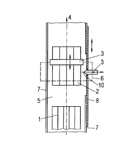
Figure 1 a top view onto the cutting device
Figure 2 a longitudinal cut, and
Figure 3 a top view onto another cutting device
The cuboid bales 2 consisting for example of waste paper arc transported in
conveying
direction 4 by a conveying apparatus 5 in the embodiment of a conveyor for
further
processing to a downstream processing device, for example a pulper. For this
purpose
strapping 1 which is present on all sides of bale 2 must be severed.
According to the arrangement illustrated in Figures 1 and 2, severing of
strapping 1 occurs by
means of a cutting device which consists substantially off two cutter bars 3,
each of which are
equipped with a cutting edge 10 pointing toward bale 2.
To sever strapping 1, cutter bars 3 are pressed in the direction of respective
bales 2. After
severing, cutter bar 3 returns.
So that severing of strapping 1 is not impaired through the movement of bales
2 on conveying
apparatus 5, but that on the other hand conveying apparatus 5 can be operated
continuously,
cutter bars 3 are moved continuously synchronously with conveying apparatus 5
by a
traversing device 6 during the severing process that is while being pressed
upon. After
cutting, traversing device 6 returns cutter bars 3 into the starting position.
4a
CA 2834316 2018-06-05

CA 02834316 2013-10-25
WO 2012/146486 Al
PCT/EP2012/056634
In order to ensure that as far as possible all strapping 1 is severed one
cutting bar 3 is located
above bales 2 and another laterally adjacent. Whereas upper cutter bar 3 is
pressed downward
onto bale 2 for cutting, lateral cutter bar 3 is pressed against the
respective side of bale 2.
It should thereby be prevented that pieces of bale 2, in particular in the
region of the cutting
device fall off conveying device 5, thus impairing its function. Bales 2 are
therefore guided
laterally by side walls 7, 8 which extend in conveying direction 4, and which
in a simple
embodiment consist of guide plates.
During cutting conveying device 5 can thus locate bale 2 relative to upper
cutter bar 3, and a
lateral side wall 7 relative to the lateral cutter bar 3.
Lateral side wall 8 is connected with traversing device 6 in this region in
order to also protect
the region around lateral cutter bar 3 from contamination. This means that it
is moved back
again together with lateral cutter bar 3 in conveying direction 4. In order
that lateral cutter bar
3 can be moved unimpeded through side wall 8 to bale 2 and away again, lateral
side wall 8 is
provided with a slot 9.
To complete the guidance, lateral side wall 8 which is connected with
traversing device 6
transitions at both ends located in and opposite traversing direction into a
stationary side wall
7. For this purpose traversing 8 and stationary side wall 7 overlap each other
in each position
of cutter bar 3.
In contrast thereto, Figure 3 shows a cutting device whereby always 2 bales
are deposited
adjacent to one another on conveying apparatus 5 transversely to conveying
direction 4.
To sever all strapping 1 of both bales 2 a lateral cutter bar 3 is located
adjacent to upper

CA 02834316 2013-10-25
WO 2012/146486 Al PCT/EP2012/056634
cutter bar 3 on both sides of conveying device 5. Both lateral cutter bars 3
are connected with
respective side wall 8 as well as with upper cutter bar 3 with common
traversing device 6.
Since the lateral cutter bars 3 are pressed from the opposite sides of bales 2
against them,
bales 2 are thereby held in place at the same time during severing of
strapping 1.
6

Representative Drawing
A single figure which represents the drawing illustrating the invention.
Administrative Status

For a clearer understanding of the status of the application/patent presented on this page, the site Disclaimer , as well as the definitions for Patent , Administrative Status , Maintenance Fee  and Payment History  should be consulted.

Administrative Status

Title Date
Forecasted Issue Date 2019-07-30
(86) PCT Filing Date 2012-04-12
(87) PCT Publication Date 2012-11-01
(85) National Entry 2013-10-25
Examination Requested 2017-02-08
(45) Issued 2019-07-30

Abandonment History

There is no abandonment history.

Maintenance Fee

Last Payment of $347.00 was received on 2024-04-02


 Upcoming maintenance fee amounts

Description Date Amount
Next Payment if standard fee 2025-04-14 $347.00
Next Payment if small entity fee 2025-04-14 $125.00

Note : If the full payment has not been received on or before the date indicated, a further fee may be required which may be one of the following

  • the reinstatement fee;
  • the late payment fee; or
  • additional fee to reverse deemed expiry.

Patent fees are adjusted on the 1st of January every year. The amounts above are the current amounts if received by December 31 of the current year.
Please refer to the CIPO Patent Fees web page to see all current fee amounts.

Payment History

Fee Type Anniversary Year Due Date Amount Paid Paid Date
Application Fee $400.00 2013-10-25
Maintenance Fee - Application - New Act 2 2014-04-14 $100.00 2013-10-25
Maintenance Fee - Application - New Act 3 2015-04-13 $100.00 2015-04-01
Maintenance Fee - Application - New Act 4 2016-04-12 $100.00 2016-04-05
Request for Examination $800.00 2017-02-08
Maintenance Fee - Application - New Act 5 2017-04-12 $200.00 2017-03-23
Maintenance Fee - Application - New Act 6 2018-04-12 $200.00 2018-03-21
Final Fee $300.00 2019-02-25
Maintenance Fee - Application - New Act 7 2019-04-12 $200.00 2019-03-20
Maintenance Fee - Patent - New Act 8 2020-04-14 $200.00 2020-03-30
Maintenance Fee - Patent - New Act 9 2021-04-12 $204.00 2021-03-29
Maintenance Fee - Patent - New Act 10 2022-04-12 $254.49 2022-04-04
Maintenance Fee - Patent - New Act 11 2023-04-12 $263.14 2023-04-03
Maintenance Fee - Patent - New Act 12 2024-04-12 $347.00 2024-04-02
Owners on Record

Note: Records showing the ownership history in alphabetical order.

Current Owners on Record
VOITH PATENT GMBH
Past Owners on Record
None
Past Owners that do not appear in the "Owners on Record" listing will appear in other documentation within the application.
Documents

To view selected files, please enter reCAPTCHA code :


To view images, click a link in the Document Description column. To download the documents, select one or more checkboxes in the first column and then click the "Download Selected in PDF format (Zip Archive)" or the "Download Selected as Single PDF" button.

List of published and non-published patent-specific documents on the CPD .

If you have any difficulty accessing content, you can call the Client Service Centre at 1-866-997-1936 or send them an e-mail at CIPO Client Service Centre.


Document
Description 
Date
(yyyy-mm-dd) 
Number of pages   Size of Image (KB) 
Abstract 2013-10-25 2 79
Claims 2013-10-25 3 64
Drawings 2013-10-25 2 23
Description 2013-10-25 6 205
Representative Drawing 2013-10-25 1 6
Cover Page 2013-12-12 2 38
Examiner Requisition 2017-12-27 4 287
Amendment 2018-06-05 7 248
Description 2018-06-05 7 225
Claims 2018-06-05 2 74
Final Fee 2019-02-25 2 81
Office Letter 2019-06-20 1 44
Representative Drawing 2019-06-28 1 4
Cover Page 2019-06-28 1 34
PCT 2013-10-25 9 265
Assignment 2013-10-25 4 119
Correspondence 2013-12-04 1 21
Correspondence 2014-02-12 2 47
Request for Examination 2017-02-08 2 74
Amendment 2017-03-29 2 38