Note: Descriptions are shown in the official language in which they were submitted.
CA 02834586 2013-10-28
WO 2012/162214
PCT/US2012/038768
TUBULAR CONNECTION AND ASSOCIATED THREAD FORM
TECHNICAL FIELD
[0001] The present application is directed to tubular connections and,
more
particularly, to a tubular connection having a thread form that is configured
to increase
resistance to axial compressive loading.
BACKGROUND
[0002] The Oil & Gas upstream production industry drills wells of ever
increasing depth and complexity to find and produce raw hydrocarbons. The
industry
routinely uses steel pipe (Oil Country Tubular Goods) to protect the borehole
(casing)
and to control the fluids produced therein (tubing). Casing and tubing are
made and
transported in relatively short lengths and installed in the borehole one
length at a time.
[0003] One way to drill a borehole more efficiently is to conserve
borehole
diameter. The most straightforward way to achieve this is to minimize the
diameter of
the pipe connections. Two types of premium oilfield connections, namely
integral flush
joints and slim diameter high performance connections have been utilized for
these
purposes. The outer diameter of a flush joint connection is substantially the
same as the
outside diameter of the body of the pipe. In other words, the connection is
contained
within the wall thickness of the pipe body.
[0004] It would be desirable to provide slim diameter and flush-type
connections, as well as other connections, with improved compression ratings.
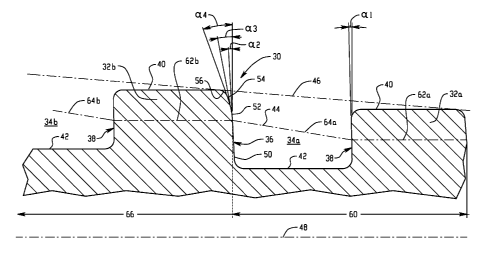
To
better understand compressive strength in flush and slim-diameter connections,
some
terminology should be established. Threads include a raised portion, the ridge
or tooth,
that fits into the recessed thread groove. The thread form is defined by a
root, crest,
stab flank, and load flank, each of which is actually a helically extending
surface. As
exemplified by Fig. 1, a profile (i.e., 2-dimensions) of the thread form is
defined by a
cross-sectional plane extending radially outward from a central axis of the
tubular
member or thread and includes a repeating "sequence" of ridge segments 10aõ
10b, 10c
and groove segments 12a, 12b, 12c, each ridge segment defined by the stab
flank 14,
crest 16 and load flank 18, and each groove segment defined by the load flank
18, root
20 and stab flank 14. Each groove segment of the profile is formed by a
respective
axial segment of the helical groove of the three-dimensional thread and each
ridge
1
segment of the profile is formed by a respective axial segment of the helical
ridge of the three-
dimensional thread.
[0005] The "pitch line" is an imaginary line 22 on the thread form profile
that intersects the stab
flank and the load flank such that the axial width WR of the thread ridge
equals the axial width WG
of the thread groove. The load flank and the stab flank are traditionally
angled to create clearances
between the tooth and groove so the two members that comprise the thread can
fit together initially
and be assembled without damage. The stab flank angle as and load flank angle
as are taken as
positive as illustrated in Fig I. The included angle al is the algebraic sum
of the two angles.
[0006] Square threads have substantially no flank angle and therefore are
desirable because they
provide good tension and compression load transfer. As described in U.S.
Patent No. 6,322,110,
square or near square threads may include at least one relieved surface on the
stab flanks that
extends from the crest to some point on the stab flank surface; i.e., a
surface with a larger stab flank
angle to create additional clearance for the load flanks during make-up of the
connection. The larger
angles(s) alleviate some of the large thread flank clearance concerns. The
clearance between the
load flanks is "transferred" to the stab flanks as the connection ends come in
contact and further
torque is applied. Further make-up of the connection may allow the stab flanks
to come back in
contact, but typically only creating a helical point or line of contact or
substantive contact that is
only able to absorb so much stress upon final make-up.
[0007] As described in the preferred embodiment of U.S. Patent No. 6,322,110,
multiple angles
(i.e., relieved surfaces) are used on the stab flank. In the "stabbed"
position, i.e., as the male (or
pin) of one connection is initially placed into the female (or box) of the
mating connection, these
surfaces enable the stab-flank of the pin thread to rest on the stab flank of
the box thread while the
load flanks have sufficient clearance to allow thread engagement as the pin is
rotated to be "made-
up," i.e., rotated towards the final, fully engaged position of the
connection. Furthermore, the
relieved surface(s) cause the threads to engage such that the clearance
between the load flanks is
reduced during make-up because certain of the surfaces acted as a cam or
inclined plane to reduce
the clearance in certain parts of the thread. However, it is connection
engagement (i.e., interaction
between parts of the connection other than the threads (such as a metal seal))
that actually halts the
forward progress of the threaded connection and will causes the contact within
the threaded portion
of the connection to
2
CA 2834586 2018-09-28
CA 02834586 2013-10-28
WO 2012/162214
PCT/US2012/038768
shift from the stab flank to the load flank. This same movement shifts the
existing
clearance from the load flank to the stab flank. Make-up is achieved as the
threads are
driven together by applied torque which rotates the pin member, forcing the
pin load-
flank to move relative to the box load-flank. The shape of the stab flanks are
such that
as the threads reach final position, i.e., full make-up, the pin and box
threads make two-
dimensional point contact at the pitch-line.
100081 in U.S. Patent No. 6,332,110 the pitch line of the thread form is
a
straight line that produces a pitch cone when rotated about the center axis of
the tubular
member or thread. The pitch line is located equidistant between the root and
crest
along each of the stab flank and the load flank, which is standard for tubular
connections. Controlled by tolerance limitations within the manufacturing
process, the
actual intersections of the pitch line on the stab flanks at full make-up may
have a small
clearance, surface contact, or a slight interference fit. As alluded to in the
'110 patent,
applied torque may be sufficient to initiate Poisson's Effect, elongating one
member
and compressing the other, resulting in a narrow band of contact about the
pitch line.
However, the '110 patent does not discuss any reliable technique to achieve
band
contact or any technique to achieve a wide area of band contact.
SUMMARY
[0009] In one aspect, a tubular connection includes a box member and a
pin
member. The pin member has a tapered, constant pitch thread having a root, a
crest, a
stab flank and a load flank. The stab flank of the pin member thread has a
base surface
and a second surface, the base surface extending radially outward and away
from the
root at a base angle relative to radial, the second surface extending radially
outward and
away from the end of the base surface at a second angle relative to radial,
the second
angle greater than the base angle. The box member has a tapered, constant
pitch thread
having a root, a crest, a stab flank and a load flank. The stab flank of the
box member
thread has a base surface and a second surface, the base surface extending
radially
inward and away from the root at a base angle relative to radial, the second
surface
extending radially inward and away from the end of the base surface at a
second angle
relative to radial, the second angle greater than the base angle. A profile
defined by the
root, crest, stab flank and load flank of at least one of the pin member or
the box
member results in a pitch line of the pin member or box member that is a
stepped pitch
line.
3
CA 02834586 2013-10-28
WO 2012/162214
PCT/US2012/038768
[0010] In the connection of the preceding paragraph, a first cycle of the
stepped
pitch line is defined by a first line segment passing through a first thread
ridge segment
of the profile and a second line segment passing through a first thread groove
segment
of the profile, the second line segment angularly offset from the first line
segment such
that the first line segment is not parallel to the second line segment.
[0011] In the connection of any preceding paragraph, a second cycle of
the
stepped pitch line is defined by a first line segment through a second thread
ridge
segment of the profile and a second line segment through a second thread
groove
segment of the profile, the first thread groove segment bounded by the first
thread ridge
segment and the second thread ridge segment, the second thread groove segment
adjacent the second thread ridge segment. The first line segment of the second
thread
ridge segment runs parallel to, but offset radially from the first line
segment of the first
thread ridge segment. The second line segment of the second thread groove
segment
runs parallel to, but radially offset from the second line segment of the
first thread
groove segment.
[0012] In the connection of any preceding paragraph, a thread taper
associated
with the one of the box member or the pin member is angularly offset from both
the
first line segment and the second line segment.
[0013] In the connection of any preceding paragraph, the second line
segment is
offset from a central longitudinal axis of the pin member or box member by an
angle
that is greater than any angle of offset that may exist between the first line
segment and
the central longitudinal axis.
[0014] In the connection of any preceding paragraph, each of the pitch
line of
the pin member and the pitch line of the box member is a stepped pitch line.
[0015] In the connection of any preceding paragraph, the pitch line of
the pin
member intersects the stab flank at a pin thread intersecting location
radially outward of
a mid-point of the height of the stab flank of the pin member thread, and the
base
surface of the stab flank of the pin member thread extends outward to the pin
thread
intersecting location. Likewise, the pitch line of the box member intersects
the stab
flank at a box thread intersecting location radially inward of a mid-point of
the height
of the stab flank of the box member thread, and the base surface of the stab
flank of the
box member thread extends inward to the box thread intersecting location.
4
CA 02834586 2013-10-28
WO 2012/162214
PCT/US2012/038768
[0016] In the connection of any preceding paragraph, when the connection
is
fully made up, the stab flank of the pin member thread and the stab flank of
the box
member thread are in substantive contact over a radial band.
[0017] In the connection of any preceding paragraph, the radial band of
substantive contact extends a radial distance that is equal to or greater than
at least
seventeen percent of stab flank height.
[0018] In the connection of any preceding paragraph, when the connection
is
fully made up, the mid-point of the stab flank height of the pin member
substantially
aligns with the mid-point of the stab-flank height of the box member, and the
radial
band of substantive contact extends both radially outward of and radially
inward of the
substantially aligned mid-points.
[0019] In the connection of any preceding paragraph, the stab flank of
the pin
member thread interacts with the stab flank of the box member thread during
connection make-up to move the load flank of the pin member thread into
substantive
contact with the load flank of the box member thread.
[0020] In the connection of any preceding paragraph, the stab flank of
the pin
member thread and the stab flank of the box member thread are configured to
interact
during connection make-up such that the load flank of the pin member thread
moves
into substantive contact with the load flank of the box member thread before
the pin
member thread and the box member thread reach sixty-five percent of radial
make-up
engagement depth.
[0021] In another aspect, a threaded tubular member includes an elongated
body having an axial passage therethrough. An end portion of the body has a
tapered,
constant pitch thread having a root, a crest, a stab flank and a load flank.
The stab flank
has a base surface and a second surface, the base surface extending radially
outward
and away from the root at a base angle relative to radial, the second surface
extending
radially outward and away from the end of the base surface at a second angle
relative to
radial, the second angle greater than the base angle. A profile defined by the
root, crest,
stab flank and load flank of at least one of the pin member or the box member
results in
a pitch line of the pin member or box member that is a stepped pitch line.
[0022] In the tubular member of the preceding paragraph, a first cycle of
the
stepped pitch line is defined by a first line segment passing through a first
thread ridge
segment of the profile and a second line segment passing through a first
thread groove
CA 02834586 2013-10-28
WO 2012/162214
PCT/US2012/038768
segment of the profile, the second line segment angularly offset from the
first line
segment such that the first line segment is not parallel to the second line
segment.
[0023] In the tubular member of the preceding paragraph, a thread taper
defined
by the profile is angularly offset from both the first line segment and the
second line
segment.
[0024] In another aspect, a tubular connection includes a pin member and
box
member. The pin member has a tapered, constant pitch thread having a root, a
crest, a
stab flank and a load flank. The stab flank of the pin member thread has a
base surface
and a second surface, the base surface extending radially outward and away
from the
root at a base angle relative to radial, the second surface extending radially
outward and
away from the end of the base surface at a second angle relative to radial,
the second
angle greater than the base angle. The box member has a tapered, constant
pitch thread
having a root, a crest, a stab flank and a load flank, the stab flank of the
box member
thread having a base surface and a second surface, the base surface extending
radially
inward and away from the root at a base angle relative to radial, the second
surface
extending radially inward and away from the end of the base surface at a
second angle
relative to radial, the second angle greater than the base angle. When the
connection is
fully made up, the stab flank of the pin member thread and the stab flank of
the box
member thread are in substantive contact over a wide radial band.
[0025] In the tubular connection of the preceding paragraph, the wide
radial
band of contact extends a radial distance that is equal to or greater than at
least
seventeen percent of stab flank height.
[0026] In the tubular connection of either of the preceding two
paragraphs,
when the connection is fully made up, the mid-point of the stab flank height
of the pin
member substantially aligns with the mid-point of the stab-flank height of the
box
member, and the wide radial band of contact extends both radially outward of
and
radially inward of the substantially aligned mid-points.
[0027] It has been discovered that the wide band contact mentioned above
greatly improves connection performance in compressive loading by adding area
to the
connection's cross-section that reacts to and resists compressive loads,
thereby
increasing the total compressive capacity of the connection to material yield.
Such
band contact also immediately reacts to compressive loading and limits
movement
within the connection, thereby isolating and protecting the metal seal during
6
CA 02834586 2013-10-28
WO 2012/162214
PCT/US2012/038768
mechanical or thermal load cycles and improving the tri-axial pressure
integrity of the
tubular connection.
[0028] In a further aspect, a tubular connection includes a pin member
and a
box member. The pin member has a tapered, constant pitch thread having a root,
a
crest, a stab flank and a load flank. The stab flank of the pin member thread
has a base
surface and a second surface, the base surface extending radially outward and
away
from the root at a base angle relative to radial, the second surface extending
radially
outward and away from the end of the base surface at a second angle relative
to radial,
the second angle greater than the base angle. The box member has a tapered,
constant
pitch thread having a root, a crest, a stab flank and a load flank, the stab
flank of the
box member thread having a base surface and a second surface, the base surface
extending radially inward and away from the root at a base angle relative to
radial, the
second surface extending radially inward and away from the end of the base
surface at
a second angle relative to radial, the second angle greater than the base
angle. The stab
flank of the pin member thread interacts with the stab flank of the box member
thread
during connection make-up to move the load flank of the pin member thread into
substantive contact with the load flank of the box member thread.
[0029] In the tubular connection of the preceding paragraph, the stab
flank of
the pin member thread and the stab flank of the box member thread are
configured to
interact during connection make-up such that the load flank of the pin member
thread
moves into substantive contact with the load flank of the box member thread
before the
pin member thread and the box member thread reach sixty percent of radial make-
up
engagement depth.
BRIEF DESCRIPTION OF THE DRAWINGS
[0030] Fig. 1 is a schematic view of an exemplary prior art thread form
having
a positive stab flank angle and a positive load flank angle;
[0031] Figs. 2 and 3 are schematic views of one embodiment of a thread
form
of the present invention;
[0032] Figs. 4 to 7 depict thread interaction during the make-up sequence
of
members incorporating the thread from of Figs. 2 and 3;
[0033] Fig. 8 is an enlarged view of stab flank substantive contact in an
exemplary fully made up connection; and
[0034] Figs. 9 and 10 depict exemplary connection configurations into
which
the subject thread form can be incorporated.
7
CA 02834586 2013-10-28
WO 2012/162214
PCT/US2012/038768
DETAILED DESCRIPTION
[0035] In the description that follows, like parts are marked throughout
the
specification and drawings with the same reference numerals, respectively. The
drawing figures are not necessarily to scale. Certain features of the
invention may be
shown exaggerated in scale or in somewhat schematic form and some details of
conventional elements may not be shown in the interest of clarity and
conciseness.
[0036] Referring initially to Fig. 2, a thread form profile 30 is shown
with two
ridge segments 32a, 32b and two groove segments 34a, 34b. It is recognized
that a
typical profile of the entire thread would be made up of a greater number of
ridge and
groove segments. The thread form utilizes a square or near-square form having
a stab-
flank 36 and load-flank 38 extending between crest 40 and root 42. The pitch-
line 44,
which is a stepped pitch line as will be described in greater detail below, is
shown in
dashed line form and the thread taper 46 is also shown in dashed line form.
The thread
form 30 is that of a pin member and the axial centerline 48 of the pin member
is also
shown, it being understood that the radial location of the centerline 48 is
not necessarily
to scale.
[0037] Load-flank 38 is illustrated having a load-flank angle al
(measured
against the radial axis, perpendicular to the axial direction of the tubular).
As
illustrated, stab-flank 36 includes three distinct surfaces¨(1) the stab-flank
base
surface 50 extends radially from root 42 and has a stab-flank base angle a2;
(2) the
stab-flank clearance surface 54 extending radially from crest 40 and has a
stab-flank
clearance angle of a4, where a4 is greater than a2; and (3) the stab-flank cam
surface
52 extends between stab-flank base surface 50 and stab-flank clearance surface
54 and
has a stab-flank cam angle a3, where a3 is greater than a2 and less than a4.
If the
clearance surface is not used, the cam surface extends from the end of base
surface to
the thread crest at an angle of a3. As an example, stab-flank base angle a2
may be
about 1 to 3 degrees (e.g., about 2 degrees), stab-flank cam angle a3 may be
about 8 to
12 degrees (e.g., about 10 degrees), and stab-flank clearance angle a4 may be
about 13
to 17 degrees (e.g., about 15 degrees). However, these angles are approximate
and it
should be appreciated by one skilled in the art that other angle values are
possible.
Stab-flank clearance surface 54 may be formed with an end radius 56 to
facilitate load-
flank clearance during initial engagement with a mating member. An end radius
is also
provided at the root of the stab flank and at both the crest and root of the
load flank.
8
CA 02834586 2013-10-28
WO 2012/162214
PCT/US2012/038768
[0038] In the illustrated embodiment, stab flank base angle a2 is
slightly more
positive than the load flank angle al . Also, the crest 40 and root 42
surfaces are
parallel to the axis 48. The represented thread is a constant pitch thread. It
is
contemplated that the load flank angle could also be slightly positive rather
than
slightly negative as shown. In the illustrated embodiment, the cam surface 52
extends
from the pitch line radially in a direction toward the crest and stops at a
radial location
that is colinear with the crest of the abutting, upstream thread ridge segment
(i.e., the
radially outer end of the cam surface is positioned at the same radial
distance from the
center line 48 as the adjacent smaller radius thread ridge segment).
[0039] As previously mentioned, and as shown in Fig. 2, the pitch line 44
is a
stepped pitch line. A first cycle 60 of the stepped pitch line 44 is defined
by a line
segment 62a passing through a thread ridge segment 32a of the profile and a
line
segment 64a passing through thread groove segment 34a of the profile. Line
segment
64a is angularly offset from line segment 62a such that the line segments are
not
parallel. In the illustrated embodiment, line segment 62a is parallel with the
center axis
48 of the member and line segment 64a angles radially away from the center
axis when
moving from the smaller diameter end of the thread or pin member to the larger
diameter end of the thread or pin member. However, it is recognized that both
line
segments 62a and 64a could be angled relative to the axis 48, with the angle
of line
segment 64a being greater than the angle of line segment 62a. A second cycle
66 of the
stepped pitch line 44 is defined by line segment 62b through a thread ridge
segment
32b of the profile and line segment 64h through thread groove segment 34b of
the
profile. As shown, the groove segment 34a is bounded by both the thread ridge
segment 32a and thread ridge segment 32b, and the thread groove segment 34h is
adjacent the thread ridge segment 32b. Line segment 62b runs parallel to, but
offset
radially from line segment 62a. Likewise, line segment 64b runs parallel to,
but
radially offset from line segment 64a. Notably, the thread pitch line 46 is
not parallel
with any of the line segments that make up the stepped pitch line 44, and is
therefore
angularly offset from each line segment. The three dimensional body produced
by
rotation of the subject pitch line about the longitudinal axis of the
connection is a
stepped body having a repeating sequence of cylindrical and conical sections.
In an
embodiment where both line segments 62a and 64a are angled relative to the
axis 48,
the three dimensional body produced by rotation of the pitch line would be a
repeating
sequence of conical sections with alternating degrees of taper.
9
CA 02834586 2013-10-28
WO 2012/162214
PCT/US2012/038768
[0040] As shown in Fig. 3, the pitch line 44 intersects the stab flank 36
at a pin
thread intersecting location 70 radially outward of a mid-point 72 of the
height Hs of
the stab flank 36. The base surface 50 extends outward from the root 42 to the
pin
thread intersecting location 70. The radial distance D between point 72 and
point 70
may be on the order of about eight to sixteen percent (e.g., at least about
eight and one-
half percent) of the overall stab flank height Hs.
[0041] ft is contemplated that a favorable tubular connection can be
formed by
both a pin member and a box member having the identical thread form (radially
outward thread on the pin member and radially inward thread on the box
member),
each thread form providing a profile with a stepped pitch line. With reference
to Fig. 3,
if the component was representative of a box member, point 70 would represent
a box
thread intersecting location of the pitch line that is positioned radially
inward of the
mid-point 72 of the height of the stab flank of the box member thread. The
center axis
of the member would be located above the illustrated profile rather than below
the
profile for such a box member. In such case, the base surface 50 would be
extending
radially inward to the box thread intersecting location.
10042] Referring now to Figs. 4-7, a tubular connection make-up sequence
for a
representative pin member 80 and box member 82 (both shown only in partial
cross-
section) is depicted.
[0043] The exact number of turns or rotation of one threaded member into
the
other threaded member required to produce the assembly sequence herein
described
may vary with the exact geometric proportions of the individual thread form
used for
the members. The sequence will be similar, but the exact number of turns may
vary.
100441 The corner radius and the clearance flank combine to provide
clearance
between the load flanks of the thread ridge and thread groove as illustrated
in the stab
position of Fig. 4. This clearance facilitates the entry of the thread ridge
into the thread
groove. During the first turn, stab flank engagement is between the clearance
surfaces
54, 54' of the two threaded members. The angle of the clearance flank draws
the load
flanks closer together as the thread is rotated into increased engagement. If
the thread
of the members contains a cam surface 52, 52', as shown, as the threaded
assembly
enters its second turn (Fig. 5), stab flank contact shifts from the clearance
surfaces 54,
54' to the cam surfaces 52, 52'. If not, assembly during the second turn
remains on the
clearance flank. Continuing assembly, i.e., rotation of one member into the
other
CA 02834586 2013-10-28
WO 2012/162214
PCT/US2012/038768
member closes the clearance between load flanks. In the example illustrated,
at the end
of the second turn (Fig. 6), the clearance is almost closed.
[0045] As the connection enters its third turn, the thread groove and
thread
ridge's load flanks engage, or are moved into substantive contact. This
engagement or
substantive contact can occur: before the stab flank base surfaces 50, 50'
engage (i.e,
before the thread intersecting locations 70, 70' of the stab flanks reach each
other), in
the case of threads with a small interference fit between the stab flanks, and
as
illustrated by Figure 6. Alternatively, the engagement or substantive contact
of the load
flanks can also occur at the intersection of the stab flank pitch lines (i.e.,
when the
thread intersecting locations 70, 70' of the stab flanks reach each other), in
the case of
threads that just make contact, starting at the intersections of the pitch
lines on the load
flanks. In still another alternative, the engagement or substantive contact of
the load
flanks can also occur after the pitch lines have passed each other (i.e.,
after the thread
intersecting locations 70, 70' of the stab flanks pass each other, placing
location 70'
radially inward of location 70 per Fig. 7), in the case where a small
clearance exists
between the stab flanks.
[0046] At this juncture, all clearance between the threads is gone, or
due to
tolerances, substantively gone. This elimination of larger gaps between both
the load
and stab flanks, regardless of other events within the threaded connection
such as
engagement of metal seals or torque shoulders, is one distinguishing feature
of the
subject tubular connection. As a function of the tolerances of the tool
inserts that are
used to machine the thread form (on the order of less than 0.001 of an inch)
the threads
may have a small clearance between flanks, no clearance between flanks, or a
small
interference fit between the thread flanks. In this regard, as used herein the
terminology "substantive contact" is intended to encompass both direct contact
(e.g.,
either just in contact or in contact via an interference fit) and near contact
(e.g., surfaces
within 0.002" of each other). Fig. 6 illustrates the case of a small
interference fit, just a
small rotational increment past the 2 turn position, where the stab flank
engagement is
still on the cam surfaces (or clearance surfaces if the cam surface is not
present). The
detailed view of both load and stab flank show that practically no clearance
exists
between the stab or the load flanks of the threads.
[0047] As the connection continues to be engaged, the base surface of the
stab
flank and the load flank continue to slide upon the respective mating surfaces
until the
root and crests of the thread engage. Note, either the root or the crest will
engage first,
11
CA 02834586 2013-10-28
WO 2012/162214
PCT/US2012/038768
followed shortly by the other. The order will again depend on the tolerances
of the
inserts and machined parts.
[0048] Fig. 8 is a detail view of the stab flanks of the thread of Fig. 7
at full
thread assembly. The broad band of substantive contact 90 is readily apparent.
As
shown, when the connection is fully made up, the mid-point of the stab flank
height of
the pin member substantially aligns with the mid-point of the stab-flank
height of the
box member, and the radial band of substantive contact extends both radially
outward
of and radially inward of the substantially aligned mid-points. The band of
substantive
contact should be equal to or greater than 17% (e.g., preferably at least
about 22%) of
the stab flank height Hs as previously noted. Achieving such a wide band of
contact
through Poisson's effect alone will result in thread damage and therefore is
not
commercially practical.
[0049] It should be appreciated that the threaded tubular connection of
the
present application may be used in an integral joint or in a coupled joint for
tubular
members. In an integral joint the pin and box members are joined integrally to
the ends
of the tubular members. In a coupled joint, a threaded coupling joins the
threaded ends
of the tubular members. The threaded tubular connection of the present
invention is
also applicable to all types of oil field tubulars including drill pipe,
casing, and tubing.
The connection may be used on plain end pipe, cold formed swaged ends, or hot
forged
upset ends.
[0050] In desirable embodiments, the tubular connection is typically
included in
the broad group identified as slim-line, high performance connections. The
connection
may be used in various embodiments such as integral flush-joint, with or
without
crimped sections, integral swaged with or without swaged sections, hot-forged
upset on
one or both members, or coupled with or without crimped pin ends. For either
an
integral or coupled connection, it is envisioned that the thread forms can be
used in
conjunction with other common premium connection features such as, without
limitation, one or more metal seals (both internal and external), one or more
torque
shoulders for positive position stop (inside, outside, or center), and run-in/
run-out
threads.
[0051] Exemplary connection configurations in which the thread form could
be
used are shown in Figs. 9 and 10. In the slim-line flush joint 100 of Fig. 9,
both the pin
member 80 and box member 82 have a single tapered constant pitch thread. In
the
center-shoulder seal joint 102 of Fig. 9, both pin and box member have a
respective
12
CA 02834586 2013-10-28
WO 2012/162214
PCT/US2012/038768
pair of threads stepped in relation to each other and spaced apart by a center
shoulder
seal 104. Other connection configurations incorporating the thread form are
contemplated.
[0052] The wide band contact achieved by the teachings herein contributes
greatly to connection performance in compressive loading by adding area to the
connection's cross-section that reacts to and resists compressive loads,
thereby
increasing the total compressive capacity of the connection to material yield.
Such
wide band contact also reacts immediately to compressive loading and limit
movement
within the connection, thereby isolating and protecting the metal seal during
mechanical or thermal load cycles and improving the tri-axial pressure
integrity of the
connection.
[0053] It is to be clearly understood that the above description is
intended by
way of illustration and example only and is not intended to be taken by way of
limitation. Changes and modifications could be made.
[0054] What is claimed is:
13