Note: Descriptions are shown in the official language in which they were submitted.
CA 02834684 2015-01-05
SURGICAL MESH WITH DIMENSIONALLY STABILIZED PORE
Field of the Invention
The embodiments herein are directed to a system and fabric having at least one
dimensionally
stabilized pore and a method of making the same.
Summary of the Invention
In a broad aspect, the present invention provides a method of stabilizing a
pore within a mesh
fabric comprising the steps of: providing a mesh knit fabric made of a
plurality of thermoplastic
polymer yarns, the fabric having a first pore, the first pore having a first
perimeter; causing at
least a portion of the fabric surrounding the pore to be temporarily held
taut; providing a support
having a support outer perimeter; inserting the tapered support into the first
pore so that the first
pore perimeter is in contact with the support outer perimeter; and placing the
taut fabric and
support in an oven for a predetermined time at a predetermined temperature,
whereby the first
pore perimeter permanently assumes that shape of the outer support perimeter.
In another broad aspect, the present invention provides a system for forming a
stabilized pore
within a mesh fabric comprising: a mesh fabric having at least one pore, said
pore having a pore
perimeter; and a frame having a support having a support outer perimeter, the
support being
received into the pore so that the pore perimeter is in contact with the outer
support perimeter,
whereby when the fabric is taut within the frame and is heat set for a
predetermined time at a
predetermined temperature, the first pore permanently assumes the dimension of
the outer
support perimeter.
In another broad aspect, the present invention provides a fabric comprising: a
thermoplastic
polymer knit having a plurality of pores therein, said pores having pore
perimeters between
knitted yarns in a knit pattern; and at least one heat set distended pore
having a distended pore
perimeter between knitted yarns, wherein the perimeter of the heat set pore is
permanently fixed
and uninterrupted.
Description of the Drawings
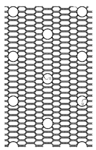
Figure 1 is a front view of surgical mesh fabric.
Figure 2 is a perspective exploded view of the system of the first embodiment.
1
CA 02834684 2015-01-05
Figure 3 is a front, side and perspective view of the pin frame assembly of
the first embodiment.
Figure 4 is a front, top, side and perspective view of a pin section of the
pin frame assembly of
Figure 3.
Figure 5 is a front, side and perspective view of the peg plate of the system
of Figure 2.
Figure 6 is a front, side, rear, and perspective view of the taper of the
system of Figure 2.
Figure 7 is a front view of the surgical mesh fabric having dimensionally
stabilized pores.
Figure 8 is an enlarged view of the surgical mesh fabric of Figure 7.
Figure 9 is a photograph of the surgical mesh fabric having dimensionally
stabilized pores, as
similarly shown in Figure 8.
Description of the Invention
Surgical mesh fabric has a number of different uses. In particular, surgical
mesh fabric may be
used in a variety of procedures including reinforcement of the pelvic floor or
the abdominal
wall. Surgical knit mesh can be manufactured in a variety of different ways so
as
la
CA 02834684 2013-10-29
WO 2012/158590
PCT/US2012/037718
to create a final product that has different size pores and different tensile
strengths and
flexibility characteristics to suit the particular application. Where surgical
mesh is used in the
reinforcement of pelvic floor or abdominal wall procedures, it is desirable to
make the pore
size as large as possible so as to encourage cell in-growth. However, if pore
size becomes
too large, tensile strength may be compromised. Thus, for an effective
material for use in the
reinforcement procedure for a pelvic floor or an abdominal wall, the pore size
becomes a
compromise between maintaining the necessary tensile strength in the material
and the desire
to achieve an open structure to encourage cell in-growth.
In some applications, it is desirable to incorporate surgical mesh as a part
of a medical device.
As such, there may be a need to join or affix the mesh with other parts or
layers of the
medical device. Often times the mesh is joined to a device or part by fixing
the mesh to the
device with a rivet or other joining means. When a rivet is used, the mesh
must have a
sufficiently large opening to receive the rivet. It would be a simple
manufacturing step to cut
or punch the appropriate sized hole into the mesh to accommodate any
attachment of the
mesh to a rivet or other joining mechanism. However, the tensile strength of
the mesh is
diminished when the fibers forming the mesh are cut. In addition, the cut
fibers may act as an
irritant when used as part of an implantable device. Furthermore, the cut ends
add a risk that
a free end or fiber may dislodge or loosen and become separated from the
device causing
further complications to the patient. Thus, it is desired to form the needed
hole in the fabric
by a means other than cutting to maintain the strength of the mesh and thus
the overall
performance of the assembly.
The preferred mesh fabric of the embodiments described herein incorporates a
way of
forming a pore in the mesh fabric without compromising the integrity of the
mesh. In
particular, the system, method and fabric of the preferred embodiments
described herein
create a dimensionally stabilized pore which is a preferred advantage in
manufacture. The
term "dimensionally stabilized" is used to refer to a targeted pore within a
fabric that is
permanently shaped during an annealing process. The preferred embodiments, and
method
and system for making the same are described in detail below.
A first preferred embodiment 10 includes a surgical mesh knit fabric 14 made
using a 14
gauge knitting machine. The yarn comprising the mesh knit fabric 14 is 3 mil
(0.003 inch)
2
CA 02834684 2013-10-29
WO 2012/158590
PCT/US2012/037718
diameter polypropylene. However, it is anticipated that any thermoplastic
polymer may be
used in this application. The selection of a particular thermoplastic polymer
would depend
on the qualities of the product desired. In the case at hand, the first
embodiment is a mesh
knit fabric 14 having a knit pattern is as follows:
a first bar pattern chain of 1/0 - 2/3 - 2/1 - 2/3 - 2/1 - 2/3 - (1/0 - 1/2) x
3;
a second bar pattern chain of 2/3 - 1/0 - 1/2 - 1/0 - 1/2 - 1/0 - (2/3 - 2/1)
x 3; and
a third bar pattern chain of 0/0 - 1/1.
There are 26 courses per inch. The resulting warp knit fabric 14 produces a
series of pores or
holes within the knit fabric. Targeted pores 12 are those pores that will be
the target of the
system and method of the present invention which will be described in more
detail below. A
representative sample of the mesh knit fabric 14 described above is shown in
Figure 1. It
should be noted that prior to heat setting, the mesh knit fabric 14 is made in
rows of
hexagonal pores or openings. In the sample of Figure 1, there are alternating
rows of larger
hexagonal pores and smaller hexagonal pores. In the row of larger hexagonal
pores, the
pores typically measure less than about 2 mm wide and about 7 mm long.
To create the dimensionally stabilized pores of the preferred embodiment 10, a
pin frame
assembly 16 and peg plate 32 are used, as shown generally in Figure 2. The pin
frame
assembly 16 of the first preferred embodiment 10, shown in more detail in
Figure 3, includes
a rectangular frame 18. The rectangular frame 18 includes a pair of parallel
vertical sections
19 and a pair of parallel horizontal sections 21. The vertical 19 and
horizontal sections 21
form a rectangular shaped frame. The rectangular frame 18 also has an upper
surface 20 and
a lower surface 22. A plurality of upwardly extending pins 24 are fixed to the
upper surface
20 of the frame 18. In preferred embodiment 10, the pins 24 are fixed to a pin
section 42, as
shown in detail in Figure 4. Each pin section 42 includes section recesses 44.
The recesses
44 receive fasteners, such as screws (not shown), to secure the pin sections
42 to the
rectangular frame 18. The pins 24 are fixed to the section 42 at an angle 0.
It is preferable
that 0 be 75 . It should be noted that the pin angle 0 may range from about 25
off vertical to
completely vertical (i.e., 0 would be 90 ). In use, the pins 24 are fixed to
the rectangular
frame 18 with the pins angled away from the center of the frame. This
arrangement helps to
hold the mesh fabric 14 more effectively and minimize any slippage or movement
of the
fabric, which will be described in more detail below.
3
CA 02834684 2013-10-29
WO 2012/158590
PCT/US2012/037718
In the first preferred embodiment 10, the pin sections 42 have staggered rows
of pins 24.
Each row includes about 10 or 11 pins per section 42. There are about 9 pin
sections along
the length of the rectangular frame 18 and about 4.5 along the width. Further,
in the preferred
embodiment 10, the pins 24 are about 7 mm long and have a diameter of about 1
mm. The
ends of the pins are pointed. The sharp pointed end of the pins helps to grab
the mesh knit
fabric 14. The pin 24 is fixed to the pin section 42.
The pins 24 are designed to engage with the mesh fabric 14 and hold it taut
during
fabrication, which will be described in more detail below. Returning to Figure
3, the pin
frame assembly 16 also includes a pair of handles 23. One handle 23 is located
adjacent to a
vertical section 19 and one located adjacent to a horizontal section 21. The
handles 23
provide ease of handling of the pin frame assembly 16 during fabrication,
which will be
discussed in more detail below. The pin frame assembly 16 of the first
preferred embodiment
10 also includes a perforated plate 26 fixed to the lower surface 22 of the
frame 18 and
extending across the length and width of the frame. The perforated plate 26
has a series of
holes 28 extending through the plate. The dimension and position of each hole
28 is designed
to align with the peg plate 32 which will be described in more detail below.
The perforated
plate 26 has an upper perforated plate surface 27 that is joined to the lower
surface 22 of the
rectangular frame 18.
Figure 5 shows the peg plate 32 of the first embodiment 10. The peg plate 32
is generally flat
and has a similar shape to that of the rectangular frame 18. The peg plate 32
has a series of
upwardly projecting pegs 34 extending perpendicular from the plane of the peg
plate. The
arrangement of the pegs 34 is such that they are received by the holes 28 of
the perforated
plate 26 when the pin frame assembly 16 is lowered over the peg plate which is
described in
more detail below. It should be noted that the number and arrangement of pegs
34 may vary
as the number and location of targeted pores 12 changes. The pegs 34 may be
secured to the
peg plate 32 by threaded fasteners (not shown). Thus the peg 34 will be
located on the peg
plate 32 at a location where a dimensionally stabilized pore is desired.
Because the pegs 34
are received into the holes 28 of the perforated plate 26, the outer diameter
of the peg cannot
exceed the diameter of the hole 28.
4
CA 02834684 2013-10-29
WO 2012/158590
PCT/US2012/037718
In process, the pegs 34 are received into the perforated plate 26 and provide
positional
support to the tapers 30, shown in detail in Figure 6. In the first preferred
embodiment 10,
each taper 30 is preferably about 0.778 inches in length. Each taper 30 is
hollow having an
interior diameter 31 and a maximum outer diameter 33. It is preferred that the
interior
diameter of the taper 30 is about 0.136 inches, and the maximum outer diameter
33 is
preferably about 0.258 inches. The taper 30 has a tapered section 36 and a
cylindrical section
38. The tapered section 36 preferably angles from preferably 0.258 inches
diameter radially
inward to 0.136 inches diameter. The tapered section 36 is preferably about
0.109 inches
long. The preferred embodiment taper 30 also has a collar 40. The collar 40 is
located at the
opposite end of the taper 30 from the tapered section 36. The collar 40 is
fixed to the
cylindrical section 38 and extends radially outward. In the first preferred
embodiment 10, the
collar 40 has an outer diameter of about 0.375 inches and a thickness of about
0.039 inches.
It is important to note that the outer diameter of the collar should be
greater than the diameter
of the holes 28 in the perforated plate 26 for reasons set forth in detail
below.
To create dimensionally stabilized pores, the pin frame assembly 16 is placed
above the peg
plate 32 so that the pegs 34 are in alignment with the holes 28 in the
perforated plate 26.
Once this occurs, the pin frame assembly 16 is lowered over the peg plate 32
and the pegs
protrude upward from the perforated plate 26 and into the area surrounded by
the rectangular
frame 18. The tapers 30 are then placed on the pegs 34 in the locations where
dimensionally
stabilized pores are desired. Each taper 30 is placed above the peg 34 and the
inner diameter
31 of the taper is received by the other diameter of the peg. Next, the mesh
knit fabric 14 is
arranged on the pin frame assembly 16 so that the fabric is pulled taut across
the length and
width of the frame 18. This is accomplished by causing one edge of the mesh
knit fabric 14
to be received by the plurality of pins 24 on one side of the rectangular
frame 18 first, then
pulling the fabric to the opposed edge to be received by the pins therein.
Then the other
remaining pair of edges is received into pins on the corresponding sides of
the rectangular
frame. Care must be taken to ensure that the fabric 14 is aligned properly so
that the targeted
pores 12 to be dimensionally stabilized are accurately positioned on the pin
frame assembly
16 directly above the tapers 30 previously positioned on the pegs 34.
5
CA 02834684 2013-10-29
WO 2012/158590
PCT/US2012/037718
As the fabric 14 is properly positioned within the pin frame assembly 16, the
targeted pore(s)
12 within the fabric located immediately above a taper 30 are forced
downwardly over the
taper 30 as the fabric is moved onto the pins 24 on the rectangular frame 18.
This causes the
targeted pore 12 to move from contact with the tapered section 36 of the taper
30 to the
cylindrical section 38 of the taper. The diameter of the targeted pore in its
knitted state is
slightly less than the outer cylindrical diameter 33 of the taper 30. This
results in a stretching
of the targeted pore 12 and further causes the yams in the area surrounding
the targeted pore
to be pulled towards the pore as a result of the stretching. As a result, the
targeted pore 12 is
in a distended state as it fully receives the cylindrical section 38 of the
taper 30 and the
surrounding yam sections have given up some of their width to achieve this
state. In other
words, the distended pore takes from the adjacent pores some of their width.
The process of
adjusting the fabric 14 over the tapers 30 continues until each pore to be
dimensionally
stabilized has a taper 30 fully inserted therein so that the pore 12 receives
the cylindrical
section 38 of the taper 30.
After all of the tapers 30 are received into the targeted pores 12, the pin
frame assembly 16 is
lifted by the handles 23 off of the peg plate 32. Because the collar 40 of the
taper 30 has an
outer diameter that is larger than the diameter of the holes 28 in the
perforated plate 26, the
tapers 30 remain in position within the fabric 14. The collar 40 of each taper
30 rests on the
upper surface 27 of the perforated plate 26. As the mesh fabric 14 shifts
slightly with the
weight of the engaged collars 40 therein, the collars 40 resting on the upper
surface of the
perforated plate 26 help to stabilize the fabric 14 so that it does not sag
with the weight of the
tapers 30.
The pin frame assembly 16 with the tapers 30 within the targeted pores 12 is
then placed in
an annealing oven. When polypropylene yam is used in the manufacture of the
mesh fabric
14, the preferred annealing temperature is between 290 F and 310 F, but
preferably 304 F,
and the anneal time is between 5 to 10 minutes, but preferably 9 minutes for
the first
preferred embodiment 10.
In general, the annealing temperature of any thermoplastic polymer yam or
fiber is
somewhere between the fabrication temperature and the melting temperature of
the yam. A
6
CA 02834684 2013-10-29
WO 2012/158590
PCT/US2012/037718
differential scanning calorimeter analysis, will indicate the melting point
and any other heat
set activity of the tested fiber, yarn or the fabric. Where the yarn or fiber
has been previously
heat set, it is necessary to exceed any previous heat set temperature in order
to effectively
anneal the fiber or fabric a second time. However, where the fiber or yarn has
not been
previously heat set, arriving at the most effective annealing temperature is a
matter of trial
and error. If the anneal temperature is too close to the melting temperature,
the mesh fabric
may begin to thermally degrade. If the temperature is too close to fabrication
temperature, an
insufficient level of annealing will occur and the heat set will be
ineffective. It should also be
noted that the annealing process is a factor of time as well as temperature.
Heat accumulation
will occur to some extent in any annealing process. The extent of heat
accumulation will
vary depending on anneal time, temperature and other fabrication factors such
as materials
used in the process.
With regard to the fabrication of the first preferred embodiment 10, when the
anneal time has
elapsed, the pin frame assembly 16 is removed from the oven and allowed to
cool. The pin
frame assembly 16 is repositioned over the peg plate 32. The pin frame
assembly 16 is
lowered onto the peg plate 32 so that the tapers 30 are again received into
the pegs 34. After
sufficient cooling time has elapsed, preferably at least five (5) minutes, the
fabric 14 is then
disengaged from the pins 24 along the edges of the rectangular frame 18. The
cooling also
causes the targeted pore 12 to disengage from contact with the cylindrical
section 38 of the
taper 30. Upon removal of the fabric 14, the targeted pores 12 are permanently
enlarged and
have permanently assumed the shape of the cylindrical section 38 of the taper
30. The fabric
14 incorporating the dimensionally stabilized pores 12 is now ready for
further
manufacturing. A drawing of the resulting dimensionally stabilized pore 12 in
the surgical
mesh fabric is shown in Figure 7, and in detail in Figure 8, and also shown in
a photograph,
which is Figure 9.
Using the preferred mesh knit fabric described above and after forming
stabilized pores
therein, a burst strength test was conducted on samples of the preferred
embodiment
described herein. The burst strength test is described as follows.
7
CA 02834684 2015-01-05
The preferred embodiment of the present invention is designed to maintain
strength of the
fabric while providing pores or holes in the fabric for joining or fastening
to other
components of a medical device. Applicant has tested the strength of the
fabric of the first
preferred embodiment 10, in comparison to fabric without any holes or pores
(Column A)
and with fabric with holes made by cutting (Column C). The results are
provided below in
Table 1. Ln column A are mesh samples made using the warp knit fabric
described herein,
but without the addition of the formation of the pores 12. In column B are
mesh samples
made in accordance with the detailed description above including the pores 12.
In column C
are mesh samples made using the warp knit fabric described herein but instead
of creating
pores 12, the warp knit fabric was cut with holes in the same location as the
pores 12 of the
warp knit fabric of the first embodiment 10. The test was conducted in
accordance with
ASTM D 3786-06 and using a TruburstTm 2 Model 810 Intelligent Bursting
Strength Tester.
Each test sample was placed so that the center of a cut, dimensionally
stabilized or knit pore
was centered within the test area. The test area was a 7.3 cm2 circle. As can
be seen from the
results, the strength of the mesh fabric with the dimensionally stabilized
pores is generally
greater than fabric with pores cut therein. Further, the mesh fabric with
dimensionally
stabilized pores showed a strength nearly as high as that of fabric having no
pores therein.
Table 1- Comparison of Burst Strength (psi)
A
Standard Mesh Mesh
fabricated with Cut
Mesh Fabricated with
without fabricated Holes Equivalent to
Distended Pores
Holes Distended
Pore Size
Specimen
1 51.66 61.73 24.98
5209. 56.09 15.34
3 58.66 58.55 16.7
4 61.77 56.95 25.48
5 64.02 57.55 14.59
6 58.55 58.45 16.52
7 60.3 58.05 21.77
8 53.23 56.59 17.09
8
CA 02834684 2013-10-29
WO 2012/158590
PCT/US2012/037718
9 57.41 50.77 14.77
54.63 54.8 23.41
Average 57.232 56.953 19.065
SD 4.22 2.85 4.35
It should be noted that while this description has focused on circular pore
perimeters, it is
anticipated that pores of other shapes, such as oval, square, rectangle, and
the like, may be
dimensionally stabilized in the same manner. It should also be noted that the
pore array
5 shown and described in the first preferred embodiment may be changed to
suit a different
device. Furthermore, the diameter of the tapers and the pore diameter may be
altered to
accommodate other devices or applications.
It should be further noted that while the discussion above has focused on a
knit mesh fabric
10 for use in abdominal tissue repair, other applications of the present
invention may be made in
the area of woven or braided materials. For example, a woven fabric may be
created so as to
have one or a plurality of dimensionally stabilized pores in accordance with
the present
invention. Such dimensionally stabilized pores may be used to provide suture
guidance or
reinforcement. In addition a dimensionally stabilized pore may be created in
accordance with
the present invention so as to provide a location for attachment to a medical
device or receive
a suture or the like.
As used herein, the singular forms "a," "an," and "the" include plural
referents unless the
context clearly dictates otherwise. Thus, for example, the term "a yarn" or "a
pore" is
intended to mean a single yam or a single pore, or more than one yarn or pore.
Furthermore,
uses within the specification of terms such as "upper," "lower," "vertical,"
"horizonal," and
the like are words of convenience used to describe the structure and function
of the parts of
the embodiments herein relative to each other and are not meant in any way to
be construed
as limiting terms.
9